Table of Contents
Advertisement
Quick Links
14 through 20-Inch Design V150 and V300
. . . . . . . . . . . . . . . . . . . . . . . . . . . . . . .
. . . . . . . . . . . . . . . . . . . . . . . . . . . . .
. . . . . . . . . . . . . . . . . . . . . . . . . . . . . . . . . .
. . . . . . . . . . . . . . . . . . . . . . . . . . . . . . .
. . . . . . . . . . . . . . . . . . . . . . . . . . . . . . . .
. . . . . . . . . . . . . . . . . . . . . . . . . . . . . .
. . . . . . . . . . . . . . . . . . . . . . . . .
. . . . . . . . . . . . . . . . . . . . . . . . . .
. . . . . . . . . . . . . . . . . . . . . . . . . . . . . .
. . . . . . . . . . . . . . . . . . . . . . . . . . . . . . . . .
. . . . . . . . . . . . . . . . . . . . . . . . . . . . . . .
. . . . . . . . . . . . . . . . . . . . . . . . . . . . . . . . . .
. . . . . . . . . . . . . . . . . . . . . . . . . . . . .
. . . . . . . . . . . . . . . . . . . . . . . . . . . . . . . .
. . . . . . . . . . . . . . . . . . . . . . . . .
. . . . . . . . . . . . . . . . . . . . . . . . . . .
. . . . . . . . . . . . . . . . . . . . . . . . . . . . . . . . .
Scope of Manual
This instruction manual provides installation, opera-
tion, maintenance, and parts ordering information for
14, 16, and 20-inch Design V150 and for 14 and
16-inch Design V300 rotary control valves. For small
valves (2 through 12-inch size), refer to a separate
instruction manual. For information on
ENVIRO-SEAL
packing, see the Fisher Controls
instruction manual titled ENVIRO-SEAL Packing
System for V-Line and edisc
separate manuals for information concerning the ac-
tuator, positioner, and mounted accessories.
1. Design V150 is available in 14, 16, and 20-inch sizes. Design V300 is avail-
able in 14 and 16-inch sizes.
. . . . . . . . . . . . . . . . . . . . . . .
. . . . . . . . . . . . . . . . . . . . . . . .
. . . . . . . . . .
. . . . . . . . . . . . . . . . .
Rotary Valves . Refer to
1
1
1
2
3
4
5
5
5
5
6
6
8
W6087/IL
9
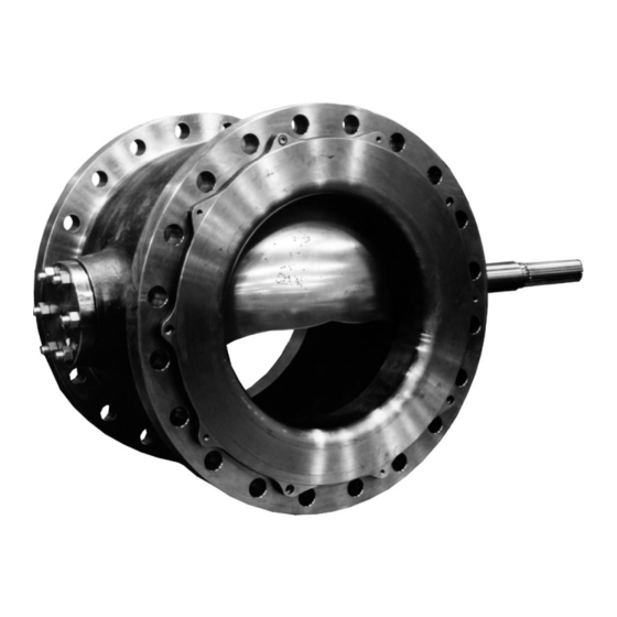
Figure 1. Design V150 and V300 Vee-Ball
9
10
10
12
14
14
Only personnel qualified through training or experience
should install, operate, and maintain a Design V150 or
15
V300 valve. If you have any questions about these
instructions, contact your Fisher Controls sales office
or sales representative before proceeding.
Description
The Design V150 or V300 Vee-Ball
V-notch ball is used in throttling or on-off service. The
Design V150 valve (figure 1) is a raised-face flanged
construction available in ANSI Class 150. The Design
V300 valve is a raised-face flanged construction avail-
able in ANSI Class 300. The splined valve shaft con-
nects to a variety of rotary actuators.
Instruction Manual
Form 5316
March 1995
Size 16-Inch Valve
valve with a
Advertisement
Table of Contents

Related Manuals for Fisher V150


Summary of Contents for Fisher V150
-
Page 1: Table Of Contents
ANSI Class 300. The splined valve shaft con- tuator, positioner, and mounted accessories. nects to a variety of rotary actuators. 1. Design V150 is available in 14, 16, and 20-inch sizes. Design V300 is avail- able in 14 and 16-inch sizes. -
Page 2: Specifications
1. The pressure or temperature limits in this manual and any applicable code limitations, should not be exceeded. 2. Refer to the appropriate Bulletin 51.3:V150 or 51.3:V300 for additional information. Table 2. Valve Sizes, Drive Shaft Diameters, and Valve Assembly Weights... -
Page 3: Installation
14 through 20-Inch Design V150 and V300 Table 3. Valve Sizes, End Connection Styles, and Ratings VALVE BODY FLANGE COMPATIBILITY RATING FACE-TO-FACE DIMENSION MATERIAL ANSI Class 150 (V150) 14 and 16-Inch Valves: ASME B16.10 Short ASME/ANSI B16.34-1988 Class 150 raised-face... -
Page 4: Maintenance
3. 20-inch, class 150 valves do not comply with ANSI B16.10 (Short). 20-inch valves are not available in class 300. 13B6967-B A6064-1/IL Figure 2. Required Clearances for Installation of Design V150 and V300 Valves 7. For hazardous applications, attach the optional bonding strap assembly (key 131, figure 4) to the... -
Page 5: Packing Maintenance
14 through 20-Inch Design V150 and V300 Use bypass valves or completely actuator adjustments must be made with the valve out shut off the process to isolate the valve of the pipeline. from process pressure. Relieve process Disassembly pressure on both sides of the valve. -
Page 6: Assembly
14 through 20-Inch Design V150 and V300 4. When removing the lever (do not loosen the actua- follower nuts (key 20). Tighten the nuts far enough to tor turnbuckle adjustment), remove the actuator stop leakage during operating conditions. mounting screws and nuts (keys 23 and 24), and re- move the actuator. - Page 7 14 through 20-Inch Design V150 and V300 A6063/IL 42B8445-B B2412/IL Figure 3. Packing Arrangements...
-
Page 8: Disassembly
14 through 20-Inch Design V150 and V300 ACTUATOR Key numbers are shown in figure 9, unless otherwise VALVE BODY indicated. 1. Isolate the control valve from the line pressure, re- lease pressure from both sides of the valve, and drain the process media from both sides of the valve. -
Page 9: Assembly
14 through 20-Inch Design V150 and V300 3. For valves with composition ball seals: Install the composition seal (key 11) into the valve body. Install the gasket (key 15) on the valve body. Install the seal protector ring (key 3) into the valve body. -
Page 10: Disassembly
14 through 20-Inch Design V150 and V300 Refer to the Ball Seal Replacement procedures to 4. Remove the flange nuts (key 47), the bottom flange remove the seal from the valve. (key 44), and gasket (key 45) from the valve. Use a hoist to lift valve body slightly. - Page 11 14 through 20-Inch Design V150 and V300 For the valve body, use a press and ram to install 4. Carefully lift the valve body until the drive shaft (key the bearings. Refer to figure 6 for dimensions and toler- 6) can be inserted through valve shaft bore and bear- ances of the ram and bearings.
-
Page 12: Actuator Mounting
14 through 20-Inch Design V150 and V300 43B7128-A A6062/IL Figure 6. Ram Construction and Bearing Installation 6. Welding the pins (key 7): the drive shaft horizontal and the V-notch ball closing in the downward direction (see figure 7). Note WARNING... - Page 13 14 through 20-Inch Design V150 and V300 43B5324-B C0768-1/IL Figure 7. Index Mark for Actuator Lever Orientation...
-
Page 14: Determining Open Position
14 through 20-Inch Design V150 and V300 Note SEAL RETAINER OR FLANGE FACE ROTATION If it is necessary to use a right-hand valve construction in the left-hand posi- tion, it is possible to mount the valve in the left-hand position. Refer to figure 7,... -
Page 15: Parts List
14 through 20-Inch Design V150 and V300 Description Part Number Packing Set, Set includes PTFE V-ring Description Part Number packing with one carbon-filled conductive Valve Body Assembly ring, Male adapter, and female adapter If a part number is required, contact... - Page 16 14 through 20-Inch Design V150 and V300 43B6886-A/DOC 43B7128-A/DOC Figure 9. Design V150 and V300 Valve Assembly...
- Page 17 14 through 20-Inch Design V150 and V300 Description Part Number Description Part Number Radial Seal, PTFE/CG/N10276 (alloy 276C) Hex Nut, steel (6 req’d) Use w/HD Metal Ball Seal V150 14-inch 13B7012X012 SA194 grade 2H 16-inch 13B0696X012 14-inch 1A377224072 20-inch 13B6065X012...
- Page 18 14 through 20-Inch Design V150 and V300 Description Part Number Description Part Number 106* Anti-Extrusion Ring (2 req’d) 23B6562X012 14-inch 14B3045X012 Tie Cable 18A9401X012 16-inch 14B3199X012 Lubricant, Never-Seez Nickel Special 20-inch 14B3056X012 or Equivalent (not furnished with packing 107* Packing Box Ring...
- Page 19 14 through 20-Inch Design V150 and V300 Key 10* Bearing (2 req’d) BEARING MATERIAL VALVE VALVE SIZE, Silver Plated PEEK /PTFE S44004 Alloy 6B INCHES Alloy 6B 14B3651X012 14A6551X012 14A6552X012 14A6540X012 14B3653X012 13B7124X012 13B7124X022 13B7125X012 14B3655X012 14A6555X012 14A6556X012 14A6542X012 1. PEEK stands for poly-ether-ether-ketone.
- Page 20 This product may be covered under one or more of the following patents: 5,129,625; 5,131,666; 5,056,757; 5,230,498; and 5,299,812 or under pending patent. ENVIRO-SEAL, edisc, Vee-Ball, Fisher, Fisher-Rosemount, and Managing The Process Better are marks owned by Fisher Controls International, Inc. or Fisher-Rosemount Systems, Inc.
Need help?
Do you have a question about the V150 and is the answer not in the manual?
Questions and answers