
Related Manuals for Extreme Networks ExtremeSwitching 5520 Series


Summary of Contents for Extreme Networks ExtremeSwitching 5520 Series
- Page 1 ExtremeSwitching 5520 Series Hardware Installation Guide 9036817-00 Rev. AA November 2020...
- Page 2 Copyright © 2020 Extreme Networks, Inc. All rights reserved. Legal Notice Extreme Networks, Inc. reserves the right to make changes in specifications and other information contained in this document and its website without prior notice. The reader should in all cases consult representatives of Extreme Networks to determine whether any such changes have been made.
-
Page 3: Table Of Contents
1100 W AC Power Supplies........................... 24 2000 W AC Power Supply............................24 Expansion Modules......................26 V300 Virtual Port Extender..........................26 V300-8P-2X Model............................27 V300-8T-2X Model............................28 V300-8P-2T-W Model............................ 29 V300HT-8P-2X Model.............................29 V300HT-8T-2X Model.............................30 V300 Virtual Port Extender LEDs......................32 V400 Virtual Port Extender..........................32 ExtremeSwitching 5520 Series Hardware Installation Guide... - Page 4 Table of Contents Versatile Interface Modules for the ExtremeSwitching 5520 Series Switches......33 5520-VIM-4X Versatile Interface Module....................34 5520-VIM-4XE Versatile Interface Module................... 35 5520-VIM-4YE Versatile Interface Module................... 36 Site Preparation......................... 37 Planning Your Site..............................37 Operating Environment Requirements......................38 Meeting Building and Electrical Codes....................38 Setting up the Wiring Closet........................39...
- Page 5 Replacing Fan Modules....................121 Pre-Installation Requirements..........................121 Airflow Direction Requirements......................... 121 Replacing a Fan Module............................122 Monitoring the Device..................... 124 5520 Series Switch LEDs............................124 Port LEDs in Default (SYS) Mode......................125 Port LEDs in SPD Mode..........................125 ExtremeSwitching 5520 Series Hardware Installation Guide...
- Page 6 Versatile Interface Modules (VIM) Port LEDs..................... 126 5520-VIM Port LEDs in Default (SYS) Mode..................127 5520-VIM Port LEDs in SPD Mode......................127 Technical Specifications....................128 ExtremeSwitching 5520 Series Technical Specifications..............128 Fan and Accoustic Noise..........................130 Fan Speed and Temperature Variation ....................130 Power Options..............................131 Mean Time Between Failures (MTBF)....................132...
- Page 7 Table of Contents Glossary..........................157 ExtremeSwitching 5520 Series Hardware Installation Guide...
-
Page 8: Preface
ExtremeXOS 31.1 Command Reference Guide information about configuring ExtremeSwitching switches. Note If the information in an installation note or release note shipped with your Extreme Networks equipment differs from the information in this guide, follow the installation or release note. Conventions This section discusses the conventions used in this guide. - Page 9 New information. In a PDF, this is searchable text. Table 3: Command syntax Convention Description bold text Bold text indicates command names, keywords, and command options. italic text Italic text indicates variable content. ExtremeSwitching 5520 Series Hardware Installation Guide...
-
Page 10: Terminology
Providing Feedback The Information Development team at Extreme Networks has made every effort to ensure the accuracy and completeness of this document. We are always striving to improve our documentation and help you work better, so we want to hear from you. -
Page 11: Subscribe To Service Notifications
Subscribe to Service Notifications The Hub A forum for Extreme Networks customers to connect with one another, answer questions, and share ideas and feedback. This community is monitored by Extreme Networks employees, but is not intended to replace specific guidance from GTAC. -
Page 12: Extremeswitching 5520 Series Overview
5520-48SE Switch Features on page 20 The ExtremeSwitching 5520 Series is a family of high-performance aggregation switches. The 5520 Series universal hardware provides end-to-end secure network segmentation, in addition to advanced policy capabilities, and offers a user-selectable choice of Extreme’s flagship switch operating systems. -
Page 13: Cooling
Stacking Each 5520 unit comes equipped with two 40GbE stacking ports. When running ExtremeEXOS, up to eight systems can be stacked using qualified QSFP28 and QSFP+ direct attach cables and optical ExtremeSwitching 5520 Series Hardware Installation Guide... -
Page 14: Operating Temperatures
Feature Licensing The ExtremeSwitching 5520 Series switches support Unified Licensing, so that you can use them with multiple operating systems. There are two methods of acquiring feature licenses: manual or through ExtremeCloud IQ™ (XIQ). -
Page 15: 5520-24W Switch Features
1 Micro-B USB console port • 2 Stacking/QSFP28 ports Figure 3: 5520-24W Front Panel 1 = 10/100/1000Mb ports 3 = Micro-B USB console port 5 = VIM port (covered) 2 = USB 1 port 4 = Stacking/QSFP28 ports ExtremeSwitching 5520 Series Hardware Installation Guide... -
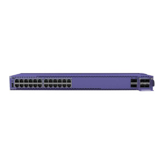
Page 16: 5520-24X Switch Features
• 2 Stacking/QSFP28 ports Figure 5: 5520-24X Front Panel 1 = 1GB/10Gb SFP+ ports 3 = Micro-B USB console port 5 = VIM port (covered) 2 = USB 1 port 4 = Stacking/QSFP28 ports ExtremeSwitching 5520 Series Hardware Installation Guide... -
Page 17: 5520-12Mw-36W Switch Features
1 Type-A USB port • 1 Micro-B USB console port • 2 Stacking/QSFP28 ports Figure 7: 5520-12MW-36W Front Panel 1 = 10/100/1000Mb ports 3 = Micro-B USB console port 5 = VIM port (covered) ExtremeSwitching 5520 Series Hardware Installation Guide... -
Page 18: 5520-48T Switch Features
Half-duplex is not supported on these ports when operating at 1Gbps. • 1 VIM slot • 1 Type-A USB port • 1 Micro-B USB console port • 2 Stacking/QSFP28 ports Figure 9: 5520-48T Front Panel ExtremeSwitching 5520 Series Hardware Installation Guide... -
Page 19: 5520-48W Switch Features
Half-duplex is not supported on these ports when operating at 1Gbps. • 1 VIM slot • 1 Type-A USB port • 1 Micro-B USB console port • 2 Stacking/QSFP28 ports Figure 11: 5520-48W Front Panel ExtremeSwitching 5520 Series Hardware Installation Guide... -
Page 20: 5520-48Se Switch Features
The front panel of the 5520-48SE switch includes: • 48 100/1000BASE-X MACsec capable SFP ports • 1 VIM slot • 1 Type-A USB port • 1 Micro-B USB console port • 2 Stacking/QSFP28 ports Figure 13: 5520-48SE Front Panel ExtremeSwitching 5520 Series Hardware Installation Guide... - Page 21 Figure 14: 5520-48SE Rear Panel 1 = Fan modules 3 = Serial console port 5 = USB 2 port 2 = Grounding lug 4 = OOB management port 6 = Locator LED 7 = Power supply slots ExtremeSwitching 5520 Series Hardware Installation Guide...
-
Page 22: Port Partitioning
• One 40 Gb port (default) • Four 25 Gb ports • Four 10 Gb ports Note: These ports do not support 1x100Gb For information about configuring partitioned ports, see the ExtremeXOS 31.1 Command Reference Guide. ExtremeSwitching 5520 Series Hardware Installation Guide... -
Page 23: Power Supplies For Use With Your Switch
OUT_OK Description (Green) (Green or Red) No AC input power connection or low AC voltage AC input good; output disabled (Red) On AC input good; output fault (Green) On AC input good; output good ExtremeSwitching 5520 Series Hardware Installation Guide... -
Page 24: Ac Power Supplies
In order to obtain 2000W output from this power supply, the PSU must be connected to a 200-240VAC source. The ExtremeSwitching 2000 W AC power supply has a keyed power inlet (C16) that requires a notched (C15) power cord. ExtremeSwitching 5520 Series Hardware Installation Guide... - Page 25 (Green or Red) No AC input power connection or low AC voltage. AC input good, 54V output disabled. (Red) On AC input good, output (54V) fault. (Green) On AC input good, DC outputs in spec. ExtremeSwitching 5520 Series Hardware Installation Guide...
-
Page 26: Expansion Modules
26 V400 Virtual Port Extender on page 32 Versatile Interface Modules for the ExtremeSwitching 5520 Series Switches on page 33 Several different hardware accessories are available for expanding the capabilities of your Extreme Networks switch. Collectively, they are referred to as expansion modules. -
Page 27: V300-8P-2X Model
The V300-8P-2X model is shipped with one 40W AC PS FRU (Model XN-ACPWR-280W). Figure 15: V300-8P-2X Front Panel 1 = DC input 2 = 10/100/1000BASE-T PoE+ ports 3 = 10Gb SFP+ ports 4 = USB port ExtremeSwitching 5520 Series Hardware Installation Guide... -
Page 28: V300-8T-2X Model
Figure 17: V300-8T-2X Front Panel 1 = DC input 2 = 10/100/1000BASE-T ports 3 = 10Gb SFP+ ports 4 = USB port 5 = Console/Management port Figure 18: V300 Virtual Port Extender Rear Panel ExtremeSwitching 5520 Series Hardware Installation Guide... -
Page 29: V300-8P-2T-W Model
The V300HT-8P-2X model requires that ExtremeXOS (EXOS) version 30.5 (or later) be installed on the switch to which it is attached. For more information about configuring EXOS for use with this equipment, see the ExtremeXOS 31.1 User Guide. ExtremeSwitching 5520 Series Hardware Installation Guide... -
Page 30: V300Ht-8T-2X Model
The Virtual Port Extender V300HT-8T-2X model is a high-temperature model that offers the following features: • Eight 10/100/1000BASE-T half/full duplex ports • Two 10Gb SFP+ ports • One USB port • One console/management port • Two DC input ports ExtremeSwitching 5520 Series Hardware Installation Guide... - Page 31 Figure 23: V300HT-8T-2X Front Panel 1 = DC inputs 2 = 10/100/1000BASE-T ports 3 = 10Gb SFP+ ports 4 = USB port 5 = Console/Management port Figure 24: V300 Virtual Port Extender Rear Panel ExtremeSwitching 5520 Series Hardware Installation Guide...
-
Page 32: V300 Virtual Port Extender Leds
All models include either two or four SFP+ ports on the faceplate of each base unit, which can be provisioned either as uplink or cascade ports. This gives administrators the option to create redundant ExtremeSwitching 5520 Series Hardware Installation Guide... -
Page 33: Versatile Interface Modules For The Extremeswitching 5520 Series Switches
You can install a versatile interface module (VIM) in a dedicated slot in the front panel of the ExtremeSwitching 5520 Series switch to provide 10/25G dedicated high speed ports. The front panel of every 5520 Series switch provides one slot to install the following: •... -
Page 34: 5520-Vim-4X Versatile Interface Module
126 for VIM LED details. 5520-VIM-4X Versatile Interface Module The 5520-VIM-4X versatile interface module provides four 10-GbE (SFP+) ports. For information about the supported optical modules, refer to the most recent version of the Extreme Optics website. ExtremeSwitching 5520 Series Hardware Installation Guide... -
Page 35: 5520-Vim-4Xe Versatile Interface Module
Figure 29: 5520-VIM-4XE Versatile Interface Module Table 13: Port Numbers for Ports on the 5520-VIM-4XE Module 5520 Series 24-port models 5520 Series 48-port models VOSS (all models) 33-36 (EXOS) 57-60 on 48-port models (EXOS) VIM slot number=2 Interface names=2/1-2/4 ExtremeSwitching 5520 Series Hardware Installation Guide... -
Page 36: 5520-Vim-4Ye Versatile Interface Module
Figure 30: 5520-VIM-4YE Versatile Interface Module Table 14: Port Numbers for Ports on the 5520-VIM-4YE Module 5520 Series 24-port models 5520 Series 48-port models VOSS (all models) 33-36 (EXOS) 57-60 on 48-port models (EXOS) VIM slot number=2 Interface names=2/1-2/4 ExtremeSwitching 5520 Series Hardware Installation Guide... -
Page 37: Site Preparation
The physical installation site must meet the following requirements for a safe and successful installation: • Building and electrical code requirements • Environmental, safety, and thermal requirements for the equipment you plan to install • Equipment rack requirements 2. Evaluating and meeting cable requirements. ExtremeSwitching 5520 Series Hardware Installation Guide... -
Page 38: Operating Environment Requirements
Site Preparation After examining your physical site and verifying that all environment requirements are met, evaluate and compare your existing cable plant with the requirements of the Extreme Networks equipment to determine if you need to install new cables. 3. Meeting power requirements. -
Page 39: Setting Up The Wiring Closet
We recommend that you consult an electrical contractor for commercial building and wiring specifications. Controlling the Temperature Extreme Networks equipment generates a significant amount of heat. It is essential that you provide a temperature-controlled environment for both performance and safety. ExtremeSwitching 5520 Series Hardware Installation Guide... -
Page 40: Controlling The Humidity Level
Table 16 summarizes the behavior of ExtremeSwitching switches when they experience high operating temperatures. Safeguards are built into all Extreme Networks switches and power supply units to minimize the risk of fire. Table 16: Thermal Shutdown and Restart Behavior Switch Model(s) -
Page 41: Rack Specifications And Recommendations
This will ensure good grounding between the chassis, rack, and earth ground. Note Because building codes vary worldwide, Extreme Networks strongly recommends that you consult an electrical contractor to ensure proper equipment grounding for your specific installation. -
Page 42: Providing Adequate Space For The Rack
Extra room on each side is optional. Warning Extreme Networks switches do not have a switch for turning power to the unit on and off. For systems using an AC power supply, power to the switch is disconnected by removing the wall plug from the electrical outlet. -
Page 43: Labeling Cables And Keeping Accurate Records
Assign a unique block of sequential numbers to the group of cables that run between each pair of wiring closets. • Assign a unique identification number to each equipment rack. • Identify all wiring closets by labeling the front panel of your Extreme Networks equipment and other hardware. • Keep accurate and current cable identification records. •... - Page 44 Every cable has a minimum bend radius, example, and fibers will be damaged if the cables are bent too sharply. It is also important not to stretch the cable during installation. Extreme Networks recommends ExtremeSwitching 5520 Series Hardware Installation Guide...
- Page 45 Table 17: Cable Distances and Types Standard Media Type MHz•km Maximum Distance Rating (Meters) 1000BASE-SX 50/125 µm multimode fiber (850nm optical window) 50/125 µm multimode fiber 62.5/125 µm multimode fiber 62.5/125 µm multimode fiber ExtremeSwitching 5520 Series Hardware Installation Guide...
- Page 46 1000BASE-T Category 5 and higher UTP cable – 1 Proprietary to Extreme Networks. Connections between two Extreme Networks 1000BASE-LX interfaces that use 10/125 µm single-mode fiber can use a maximum distance of 10,000 meters. ExtremeSwitching 5520 Series Hardware Installation Guide...
- Page 47 10BASE-T Category 3 and higher UTP cable – Table 18 Table 19 on page 47 list direct-attach cables available from Extreme Networks. Table 18: Extreme Networks 100Gb Direct-Attach Cables Cable Type Part Number Length QSFP28-QSFP28 Direct attach passive copper cable 10411 or AA1405029-...
-
Page 48: Using Rj45 Connector Jackets
• Routing UTP cable near air conditioner units • Routing UTP cable near electrical transformers In areas or applications where these situations cannot be avoided, use fiber optic cabling or shielded twisted pair cabling. ExtremeSwitching 5520 Series Hardware Installation Guide... -
Page 49: Meeting Power Requirements
Extreme Networks equipment. The web page provides specifications for power cords in each country so that you can purchase cords locally. AC power cords must meet the requirements listed in... - Page 50 UPS transfer time. UPS transition times vary between UPS models and implementations, but shorter transition times are preferred. For Extreme Networks stacking products, we recommend a UPS transition time of 20 milliseconds or less to ensure optimum performance and minimize service interruptions.
-
Page 51: Dc Power Requirements
For more information, see the following ANSI/TIA/EIA standards: • ANSI/TIA/EIA-568-A—the six subsystems of a structured cabling system • ANSI/TIA/EIA-569-A—design considerations • ANSI/TIA/EIA-606—cabling system administration • ANSI/TIA/EIA-607—commercial building grounding and bonding requirements You can access these standards at: www.ansi.org or www.tiaonline.org. ExtremeSwitching 5520 Series Hardware Installation Guide... -
Page 52: Building Stacks
SummitStack cables. All connections between stack ports must be directly between switches. A stacking connection cannot pass through a third device, for example a Virtual Port Extender or an LRM/MACsec Adapter. ExtremeSwitching 5520 Series Hardware Installation Guide... -
Page 53: Building Basic Stacks
66 and configure a vertical stack from the console on the switch at the top of the physical stack, the switches will be assigned slot numbers 1 through 8 from the top down. ExtremeSwitching 5520 Series Hardware Installation Guide... - Page 54 5. X440-G2 and X620 For example, in a stack that combines X460-G2 or X670-G2 switches with other switch models, an X460-G2 or X670-G2 switch might provide more memory and more features than other switches in the ExtremeSwitching 5520 Series Hardware Installation Guide...
-
Page 55: Summitstack Topologies
The ExtremeSwitching X465 series switches can only be stacked with themselves, and with ExtremeSwitching and X690 using V160. Note The ExtremeSwitching 5520 series switches can only stack with themselves. When easy setup compares two switches that have the same capability, the lower slot number takes precedence. - Page 56 The result forms a physical ring connection. This topology is highly recommended for normal operation. Figure 38 represents a maximal ring topology of eight active nodes. ExtremeSwitching 5520 Series Hardware Installation Guide...
- Page 57 We strongly recommend that your stack nodes be connected in a ring topology, not a daisy-chain topology, for normal operation. Figure 40, the nodes delineated as the active topology are operating in a daisy-chain configuration, even though there is physically a ring connection in the stack. ExtremeSwitching 5520 Series Hardware Installation Guide...
-
Page 58: Summitstack Terms
A stacking configuration in which stack members are connected using 10- Gbps Ethernet data ports that have been configured for stacking. These ports are located either on the switch itself or on option cards installed on the rear of the switch. ExtremeSwitching 5520 Series Hardware Installation Guide... - Page 59 The master node controls all of its own data ports as well as all data ports on the backup and standby nodes. To accomplish this, the master node issues specific programming commands over the control path to the backup and standby nodes. ExtremeSwitching 5520 Series Hardware Installation Guide...
- Page 60 Node role election priority A priority assigned to each node, to be used in node role election. The node with the highest node role election priority during a role election becomes the master node. The node with the second highest node role election priority becomes the backup. ExtremeSwitching 5520 Series Hardware Installation Guide...
-
Page 61: Planning To Create Your Stack
You must enable stacking-support individually for every switch in the stack that does not have stacking support enabled by default. • To disable stacking support, configure the switch data ports to use the Ethernet protocol instead of the stacking protocol. Use the disable stacking-support command. ExtremeSwitching 5520 Series Hardware Installation Guide... -
Page 62: Recommendations For Placing Switches For Stacked Operation
ExtremeXOS 31.1 Feature License Requirements.) To view the ExtremeXOS software version on a node, restart the node and run the command: show version {detail | process name | images {partition partition} {slot slot_number} } . ExtremeSwitching 5520 Series Hardware Installation Guide... -
Page 63: Selecting Native And Alternate Stacking Ports
[stack-ports | all] selection [native { |V160 |V320 |V400} |alternate] Note Not all options are available for all switches. • To display the stacking and stacking-support configuration, use the following commands: show stacking-support show stacking stack-ports ExtremeSwitching 5520 Series Hardware Installation Guide... -
Page 64: Combining Switches From Different Series
5520 Series switches can only stack with themselves using the SummitStack-V160. Selecting Stacking Cables Stacking connections using the native stacking ports require stacking cables that are specific to the type of stacking port. These cables are available from Extreme Networks in lengths from 0.5 meter to 100 meters. Note... - Page 65 SummitStack-V and SummitStack-V80 (supported in EXOS 30.1 and prior releases only). • To remove a switch from the stack, drag it away from the stacking column. Whenever you add or remove a switch from the stack, the statistics and recommendations update automatically. ExtremeSwitching 5520 Series Hardware Installation Guide...
-
Page 66: Setting Up The Physical Stack
For instructions to connect specific types of stacking cables, see Connecting Stacking Cables on page Using SummitStack-V160 Stacking Examples of Valid Stacking Configurations The X460-G2 accommodates the VIM-2ss SummitStack module, which provides SummitStack ports. ExtremeSwitching 5520 Series Hardware Installation Guide... - Page 67 Stack Port 2 Slot 1 Stack Port 1 Example: Basic Stack with Eight Switches Figure 43 shows cable connections for an 8-node stack using SummitStack 40G cables to connect switches with integrated SummitStack ports. ExtremeSwitching 5520 Series Hardware Installation Guide...
- Page 68 SummitStack modules. For the second switch model, the stacking ports are on installed SummitStack stacking modules. The recommended order for connecting the stacking ports is the same as for the example in Example: Basic Stack with Eight Switches on page 67. ExtremeSwitching 5520 Series Hardware Installation Guide...
- Page 69 Rack A Rack B Rack C Rack D Rack E Slot 1 Slot 2 Slot 5 Slot 3 Slot 4 Figure 45: Top-of-Rack Stack Installation ExtremeSwitching 5520 Series Hardware Installation Guide...
-
Page 70: Connecting Stacking Cables
4. Repeat steps 1 through 3 to connect the cable to the second switch. Figure 46: Connecting a SummitStack Cable Caution Avoid making sharp bends in the cable. Sharp bends can stress the cable and cause damage. ExtremeSwitching 5520 Series Hardware Installation Guide... -
Page 71: Connecting Your Stack To The Management Network
2. Push the connector into the port until you hear it click into place. Connecting Your Stack to the Management Network Before you can configure ExtremeXOS for a new stack, your management console must be connected to at least one switch in the stack. ExtremeSwitching 5520 Series Hardware Installation Guide... - Page 72 There is an alternate IP address configuration that will enable you to log in directly to each switch in the stack through its Ethernet management port. See the ExtremeXOS 31.1 User Guide for instructions to perform the software configuration for your stack. ExtremeSwitching 5520 Series Hardware Installation Guide...
-
Page 73: Installing Your Switch
Turn on the Switch on page 80 Connecting Network Interface Cables on page 81 Before you attempt to install or remove an Extreme Networks switch, read the precautions in Safety Considerations for Installing Switches on page 74. Extreme Networks switches fit into standard 19-inch equipment racks. -
Page 74: Safety Considerations For Installing Switches
Ensure that you have followed the guidance in "Preparing to Install," and ensure that you have the appropriate people and tools on hand. Installing Extreme Networks switches is easiest when there are two people to maneuver the switch and attach mounting hardware. -
Page 75: Attaching The Switch To A Rack Or Cabinet
The following figures illustrate how to attach the brackets for two common mounting options. • Figure 49 shows a mid-mount configuration using a short mounting bracket. • Figure 50 shows a front-mount configuration using a short mounting bracket. ExtremeSwitching 5520 Series Hardware Installation Guide... - Page 76 Attaching the Switch to a Rack or Cabinet Installing Your Switch Figure 49: Mid-Mount: Attaching Short Mounting Brackets ExtremeSwitching 5520 Series Hardware Installation Guide...
- Page 77 4. Secure the mounting bracket flanges to the rack, using screws that are appropriate for the rack. (Rack-mounting screws are not provided.) ExtremeSwitching 5520 Series Hardware Installation Guide...
-
Page 78: Installing Optional Components
ExtremeSwitching switches support the use of pluggable transceivers and cables in the SFP+, SFP28, QSFP+, and QSFP28 formats. For a list of the optical components supported with ExtremeSwitching devices, see the Extreme Optics website. ExtremeSwitching 5520 Series Hardware Installation Guide... -
Page 79: Pluggable Transceiver Modules
An AC power cord is not included with an AC power supply. You can purchase AC power cords for use in the US and Canada from Extreme Networks or from your local supplier. The cord must meet the requirements listed under... -
Page 80: Turn On The Switch
An AC power cord is not included with the AC power supply. You can purchase AC power cords for use in the US and Canada from Extreme Networks or from your local supplier. The cord must meet the requirements listed in Power Cord Requirements for AC-Powered Switches and AC Power Supplies page 146. -
Page 81: Connecting Network Interface Cables
Power Cord Requirements for AC-Powered Switches and AC Power Supplies page 146. To turn on an Extreme Networks switch, do the following. 1. For switches that are connected to AC power, connect the power cord to the AC power input socket on the switch (or power supply) and to an AC power outlet. -
Page 82: Activating And Verifying The Switch
The default communication protocol settings for the serial console interface are: • Baud rate: 115200 • Data bits: 8 • Stop bit: 1 • Parity: None ExtremeSwitching 5520 Series Hardware Installation Guide... -
Page 83: Logging In For The First Time On Exos
Switch : 800444-00-05 0723G-01234 Rev 5.0 BootROM: Configure the switch's IP address for the management virtual LAN (VLAN) by following the steps in Configuring the Switch's IP Address for the Management VLAN on page 84. ExtremeSwitching 5520 Series Hardware Installation Guide... -
Page 84: Configuring The Switch's Ip Address For The Management Vlan
The switch will install VOSS, then reset. Once the NOS is selected, the "5520 Boot Menu" will only wait for 3 seconds before continuing. To change the switch OS if you take no action during the initial boot, see Changing the Switch OS via the Startup Menu on page 85 ExtremeSwitching 5520 Series Hardware Installation Guide... -
Page 85: Changing The Switch Os Via The Startup Menu
Be sure that your serial connection is set properly: • Baud rate: 115200 • Data bits: 8 • Stop bit: 1 2. Press [Enter] one or more times until you see the login prompt. ExtremeSwitching 5520 Series Hardware Installation Guide... - Page 86 When prompted for the password, enter rwa. When you are logged in with the role-based authentical level of rwa, you can configure the login and password values for the other role-based authentication levels. ExtremeSwitching 5520 Series Hardware Installation Guide...
-
Page 87: Installing Expansion Modules
3. Secure the port extender to each post with rack-mounting screws (not provided). 4. Connect an AC power cord to the AC power input socket on the port extender and to an AC power outlet. ExtremeSwitching 5520 Series Hardware Installation Guide... -
Page 88: Install A V300 Virtual Port Extender On A Wall
There are several orientations for installation on a wall. To install the V300-8P-2T-W model on a wall: 1. Attach the short brackets to both sides of the extender The orientation for wall mounting should be front panel facing down. ExtremeSwitching 5520 Series Hardware Installation Guide... - Page 89 Two short brackets attached to the extender by 4 wood screws and 4 anchors, provided in the accessory kit. Figure 53: V300-8P-2T-W Wall Mounting 2. Use the optional short bracket as a template and mark the holes to be used. Extreme recommends using 2 holes per short rack ear. ExtremeSwitching 5520 Series Hardware Installation Guide...
- Page 90 Install a V300 Virtual Port Extender on a Wall Installing Expansion Modules 3. For non-PoE models, after attaching the short brackets, attach the PSUs to the PSU mounting brackets using two cable ties. Figure 54: V300-8P/8T-2X Wall Mount with PSU ExtremeSwitching 5520 Series Hardware Installation Guide...
-
Page 91: Install A V300 Virtual Port Extender Under Or On A Table Surface
Typical installation for the V300-8P-2T-W model include wall or table installations, in addition to VESA mounting. For table surface or other flat surface installation, attach the rubber feet to the underside of the virtual port extender, then place the device to the table or flat surface: ExtremeSwitching 5520 Series Hardware Installation Guide... - Page 92 There are several orientations for installtion under a table. To install a V300-8P-2T-W model under a table: 1. Attach the short mounting brackets (included in kit) to the sides of the port extender using four screws (included) for each bracket. Figure 57: Under Table Mounting ExtremeSwitching 5520 Series Hardware Installation Guide...
-
Page 93: Install A V300 Virtual Port Extender In A Vesa Mount
4. When power is connected, verify that the SYS LED on the port extender turns green. Install a V300 Virtual Port Extender in a VESA Mount The following tools and materials are required to install a V300 Virtual Port Extender with a VESA mount: • ESD-preventive wrist strap ExtremeSwitching 5520 Series Hardware Installation Guide... - Page 94 Extender to a VESA mount for 75mm x 75mm or 35mm x 75mm mounting dimensions. To install a V300 Virtual Port Extender in a VESA Mount: 1. Attach the VESA mount to the underside of the port extender using four screws (included): Figure 60: VESA Mounting ExtremeSwitching 5520 Series Hardware Installation Guide...
-
Page 95: Install A V300 In A Single Rack Mount
2. Attach the short and long ear brackets to the V300 using the screws provided. 3. Secure the bracket flanges to the rack using the customer-provided screws appropriate for the rack you are using. ExtremeSwitching 5520 Series Hardware Installation Guide... - Page 96 Installing Expansion Modules 4. After attaching the PSU bracket to the V300, attach the PSU to the PSU mounting brackets using two or four cable ties: Figure 62: V300-8P-2X Single Rack Mounting with PSU ExtremeSwitching 5520 Series Hardware Installation Guide...
- Page 97 Installing Expansion Modules Install a V300 in a Single Rack Mount Figure 63: V300HT-8P/8T-2X Single Rack Mounting with PSUs ExtremeSwitching 5520 Series Hardware Installation Guide...
-
Page 98: Install A V300 In A Dual Rack Mount
3. Attach the joint brackets to the inward side of each V300 (one with tapped screw holes facing forward, one facing rearward, using the screws provided). 4. Attach the two joint brackets together using the screws provided. ExtremeSwitching 5520 Series Hardware Installation Guide... - Page 99 5. After attaching the PSU bracket to the V300 using the provided screws, attach the PSU to the PSU mounting brackets using two, four, or eight cable ties: Figure 65: V300-8T-2X Dual Rack Mounting with PSU ExtremeSwitching 5520 Series Hardware Installation Guide...
- Page 100 Install a V300 in a Dual Rack Mount Installing Expansion Modules Figure 66: V300HT-8P/8T Dual Rack Mounting with PSUs ExtremeSwitching 5520 Series Hardware Installation Guide...
-
Page 101: Install A V300 In A Din Rail Mount
XN-DIN-MT-001 - DIN Rail mount kit For PSU XN-ACPWR-320W-HT or XN-ACPWR-40W-HT: 1. Remove all contents of the DIN Rail mount kit (XN-DIN-MT-001). 2. Attach the port extender to the DIN Rail using one DIN bracket and the screws provided. ExtremeSwitching 5520 Series Hardware Installation Guide... - Page 102 3. Attach the PSUs to the DIN bracket using cable ties, and then attach the bracket to the DIN Rail: Figure 68: V300HT-8P-2X DIN Rail Mount with dual XN-ACPWR-320W-HT PSUs 4. For PSU 16807, attach the port extender to the DIN Rail using one DIN bracket and the screws provided. ExtremeSwitching 5520 Series Hardware Installation Guide...
- Page 103 5. Attach the PSUs directly to the DIN rail: Figure 69: V300HT-8P-2X DIN Rail Mount with dual 16807 PSUs 6. For XN-ACPWR-60W-HT-DIN, attach the port extender to the DIN Rail using one DIN bracket and the screws provided. ExtremeSwitching 5520 Series Hardware Installation Guide...
-
Page 104: Install A V300-8P-2T-W Model In A Single Or Dual Rack Mount
2. Attach the short mounting brackets (included) to the sides of the port extender using the four screws (included) for each bracket. Figure 71: Single Rack Mounting Figure 72: Dual Rack Mounting 3. Align the holes in the brackets with the rack post holes. ExtremeSwitching 5520 Series Hardware Installation Guide... -
Page 105: Installing A V300-8P-2T-W Model In A Din Rail Mount
2. For option 1, attach the DIN mounting bracket to the rear of the port extender using the two screws (included) for each bracket: Figure 73: DIN Rail Mounting Option 1: Attach the Bracket ExtremeSwitching 5520 Series Hardware Installation Guide... - Page 106 Figure 75: Din Rail Mounting Option 2: Attach the Bracket 5. Align the DIN bracket with the DIN rail and attach the port extender: Figure 76: DIN Rail Mounting Option 2: Secure the Port Extender ExtremeSwitching 5520 Series Hardware Installation Guide...
-
Page 107: Connecting The V300 Virtual Port Extender To Power
However, in some cases, it may be necessary to use an alternative grounding method. In these cases, a 14 AWG wire can be connected between the grounding lug on the chassis and a nearby building ground point. ExtremeSwitching 5520 Series Hardware Installation Guide... -
Page 108: Installing A V400 Virtual Port Extender
2. On a flat surface. Mounting a Half-Duplex to Full-Duplex Converter on a Flat Surface on page 109. 3. On a wall. Mounting a Half-Duplex to Full-Duplex Converter on a Wall on page 109. ExtremeSwitching 5520 Series Hardware Installation Guide... -
Page 109: Installing Half-Duplex To Full-Duplex Converters In A 3-Slot Modular Shelf
2. Insert an anchor bolt (not provided) into each hole in the wall. 3. Place a screw (not provided) into each anchor bolt and tighten so that the screw head protrudes slightly from the wall. ExtremeSwitching 5520 Series Hardware Installation Guide... -
Page 110: Connecting A Half-Duplex To Full-Duplex Converter To Its Power Adapter
4. Connect the power adapter to an AC power source. 5. When power is connected, verify that the converter's power LED turns green. If the power LED does not turn on, recheck the connections from the connector to the power source. ExtremeSwitching 5520 Series Hardware Installation Guide... -
Page 111: Install A Versatile Interface Module In A 5520 Series Switch
• Flat head screwdriver Caution Extreme Networks VIMs are not hot-swappable. Disconnect power to the switch before removing an installed VIM or installing a new VIM. To install a versatile interface module, follow these steps: 1. Attach the ESD wrist strap to your wrist and connect the metal end to an appropriate ground point on the rack. - Page 112 Install a Versatile Interface Module in a 5520 Series Switch Installing Expansion Modules 1 = VIM module retaining screw locations ExtremeSwitching 5520 Series Hardware Installation Guide...
-
Page 113: Replacing Ac Power Supplies
1. Disconnect the AC power cord from the wall outlet and from the power supply. 2. Note the orientation of the installed power supply, and the location of the latching tab at the right of the unit. ExtremeSwitching 5520 Series Hardware Installation Guide... - Page 114 5. Verify that the replacement power supply is oriented the same way as the unit you removed, and has the same airflow direction. 6. Carefully slide the power supply all the way into the power supply bay, as shown in Figure ExtremeSwitching 5520 Series Hardware Installation Guide...
-
Page 115: Replace An 1100 W Ac Power Supply
The 1100 W AC power supplies with part number 10941 are compatible with 5520-24W, 5520-12MW-36W, and 5520-48W models. The switches have two bays for hot-swappable power supplies. In a switch with a redundant power configuration, you can replace one AC power supply without powering down the switch. ExtremeSwitching 5520 Series Hardware Installation Guide... - Page 116 3. Push the latching tab toward the power supply handle and pull outward on the handle to disengage the power supply internal connectors. Figure Figure 82: Removing an 1100 W AC Power Supply ExtremeSwitching 5520 Series Hardware Installation Guide...
- Page 117 6. Carefully slide the power supply all the way into the power supply bay. Figure Figure 83: Installing an 1100 W AC Power Supply 7. Push the power supply in until the latch snaps into place. Caution Do not slam the power supply into the switch. ExtremeSwitching 5520 Series Hardware Installation Guide...
-
Page 118: Replace A 2000 W Ac Power Supply
1. Disconnect the AC power cord from the wall outlet and from the power supply. 2. Note the orientation of the installed power supply, and the location of the latching tab at the right of the unit. ExtremeSwitching 5520 Series Hardware Installation Guide... - Page 119 Unoccupied bays must always be covered to maintain proper system ventilation and EMI levels. 5. Verify that the replacement power supply is oriented the same way as the unit you removed, and has the same airflow direction. ExtremeSwitching 5520 Series Hardware Installation Guide...
- Page 120 Always be sure that the source outlet is properly grounded before plugging the AC power cord into the AC power supply. 9. If the power supply is equipped with a power cord retainer, use the retainer to secure the power cord to the power supply. ExtremeSwitching 5520 Series Hardware Installation Guide...
-
Page 121: Replacing Fan Modules
5520 Series switches are available with front-to-back airflow. In this switch, the fan modules are labled Air Out. All installed fan modules must blow air in the same direction and must match the airflow direction of the installed power supplies. ExtremeSwitching 5520 Series Hardware Installation Guide... -
Page 122: Replacing A Fan Module
2. Slide the fan module out of the switch and set it aside. Figure 86: Removing a Fan Module 3. Verify that the airflow direction on the replacement fan module matches that of the installed fan modules. Fans with front-to-back airflow are labeled Air Out. ExtremeSwitching 5520 Series Hardware Installation Guide... - Page 123 Replacing Fan Modules Replacing a Fan Module 4. Carefully slide the replacement fan module into the switch. Figure 87: Installing a Fan Module 5. Align and fully tighten the captive retaining screws. ExtremeSwitching 5520 Series Hardware Installation Guide...
-
Page 124: Monitoring The Device
126 The following topics help you monitor the status of the switch/appliance as it is running. 5520 Series Switch LEDs ExtremeSwitching 5520 Series Front Panel Port LEDs, as described in the following table: Table 27: 5520 Series Port LEDs Color/State... -
Page 125: Port Leds In Default (Sys) Mode
2 ports are up. It is off when both ports are down. In partitioned 2x50, each LED will represent link and traffic for one 50G port. In aggregate ExtremeSwitching 5520 Series Hardware Installation Guide... -
Page 126: Port Leds In Stk Mode
There are two supported modes for ExtremeSwitching 5520-VIM port LEDs: • SYS - default, use normal port LED behavior for link, traffic, and PoE • SPD – use the port LEDs to indicate operational speed ExtremeSwitching 5520 Series Hardware Installation Guide... -
Page 127: 5520-Vim Port Leds In Default (Sys) Mode
SPD mode is used to help determine the operational speed of a port. Color and blink pattern indicate speeds, as referenced by the following table: Table 33: 5520-VIM Port LEDs in SPD Mode Color/State Speed Slow blinking green 10Gbps Solid green 1Gbps Fast blinking green 25Gbps ExtremeSwitching 5520 Series Hardware Installation Guide... -
Page 128: Technical Specifications
This section lists technical specifications for the hardware products described in this document. ExtremeSwitching 5520 Series Technical Specifications The 5520 Series includes the following switches: • 5520-24T switch • 5520-24W switch • 5520-24X switch • 5520-12MW-36W switch • 5520-48T switch ExtremeSwitching 5520 Series Hardware Installation Guide... - Page 129 1100W PSU and 3 fans 5520-48SE 15.69 lb (7.12 kg) with 350W PSU and 3 fans Table 38: 5520 Packaged Dimensions 5520 (all models) Height: 6.7 inches (16.9 cm) Width: 21.6 inches (54.8 cm) ExtremeSwitching 5520 Series Hardware Installation Guide...
-
Page 130: Fan And Accoustic Noise
Height: 1.9 inches (4.9 cm) Width: 4.2 inches (10.7 cm) 5520-VIM-4XE 0.64 lb (0.29 kg) Length: 8.6 inches (21.9 cm) 5520-VIM-4YE 0.66 lb (0.3 kg) Fan and Accoustic Noise Refer to the 5520 Data Sheet for up-to-date information. ExtremeSwitching 5520 Series Hardware Installation Guide... -
Page 131: Fan Speed And Temperature Variation
5520-24W switch 2000 W AC power supply: 100-127 V 200-240 V 5520-12MW-36W Part no. XN-ACPWR-200W-F 2000 W AC PS FB switch (front to back) 50-60 Hz, 12/10 A max 5520-48W switch Model PSSF202101A per PS ExtremeSwitching 5520 Series Hardware Installation Guide... -
Page 132: Mean Time Between Failures (Mtbf)
Note 5520-24X and 5520-24T models have 2 fan slots; All other models have 3. CPU and Memory Table 45: CPU, Memory CPU/Memory 1-core, 1.7GHz x86 ARM CPU (Cortex A72) 2 GB DDR4 ECC memory ExtremeSwitching 5520 Series Hardware Installation Guide... -
Page 133: Standards And Environmental Data
ICES-003 Class A (Canada) European EMC standards EN 55032 Class A EN 55024 EN 55035 EN 61000-3-2:2014 (Harmonics) EN 61000-3-3:2013 (Flicker) ETSI EN 300 386 (EMC Telecommunications) 2014/30/EU EMC Directive EN 55011 Class A ExtremeSwitching 5520 Series Hardware Installation Guide... - Page 134 Operational random vibration: 3 to 500 Hz at 1.5 G rms Storage & transportation Transportation temperature: -40°C to 70°C (-40°F to 158°F) conditions (packaged) Storage and transportation humidity: 10% to 95% relative humidity, non-condensing ExtremeSwitching 5520 Series Hardware Installation Guide...
-
Page 135: V300 Virtual Port Extender Specifications
Table 53: V300 Packaged Dimensions V300-8P-2X Height: 3.07 in (7.79 cm) Width: 11.52 in (29.26 cm) Length: 19.98 in (50.74 cm) V300-8T-2X Height: 3.07 in (7.79 cm) Width: 10.15 in (25.78 cm) Length: 17.61 in (44.72 cm) ExtremeSwitching 5520 Series Hardware Installation Guide... -
Page 136: Power Specifications
• 1 x 60W = PoE ports load to 30W • 2 x 30W = PoE ports load to 30W • 1 x 30W = PoE ports load to 0W V300HT-8P-2X DC Input: 54VDC, 4.5A max V300HT-8T-2X DC Input: 12VDC, 1.5A max ExtremeSwitching 5520 Series Hardware Installation Guide... -
Page 137: Standards And Environmental Data
158°F) Humidity: 5% to 95% relative humidity, non-condensing Altitude: 0 to 3,000 meters (9,850 feet) Minimum is defined as idle, with no ports linked. Maximum is defined as fans high, all ports 100% traffic. ExtremeSwitching 5520 Series Hardware Installation Guide... -
Page 138: V400 Virtual Port Extender Technical Specifications
Table 61: V400 Packaged Dimensions V400-24t-10GE2 Height: 4.49 in (11.4 cm) Width: 14.66 in (37.2 cm) Length: 22.02 in (55.9 cm) V400-24p-10GE2 Height: 4.49 in (11.4 cm) Width: 14.66 in (37.2 cm) Length: 22.02 in (55.9 cm) ExtremeSwitching 5520 Series Hardware Installation Guide... -
Page 139: Power Specifications
DC RPS input: 54 VDC, 18.52 A max • PoE ports load to 740 W for AC input only. • PoE ports load to 900 W for DC input only. • PoE ports load to 1440 W for AC+DC input. ExtremeSwitching 5520 Series Hardware Installation Guide... -
Page 140: Fan And Acoustic Sound
5.1 (Duty 30%) / 65.5 (max.) 6.8 (max.) Minimum is defined as idle, with no ports linked. Maximum is defined as fans high, all ports 100% traffic. At 25°C and 50% PoE load where applicable ExtremeSwitching 5520 Series Hardware Installation Guide... -
Page 141: Standards And Environmental Data
4 priority queues • 192Kb packet buffer Table 68: Half-Duplex to Full-Duplex Converter Packaged Dimensions Height 2.69 cm (1.06 in) Width 12.9 cm (5.08 in) Depth 6.91 cm (2.72 in) Weight 200 g (0.44 lb) ExtremeSwitching 5520 Series Hardware Installation Guide... -
Page 142: Half-Duplex To Full-Duplex Converter Power Specifications
FCC CFR 47 part 15 Class A (USA) ICES-003 Class A (Canada) EN 55022: Class A EN 55024:A2 Class A includes IEC 61000-4-2, 3, 4, 5, 6, 11 EN 61000-3-2,8 (Harmonics) EN 61000-3-3 (Flicker) 2014/30/EU EMC Directive ExtremeSwitching 5520 Series Hardware Installation Guide... -
Page 143: 350 W Ac Power Supplies Technical Specifications
12.5 A max at 115VAC and 6A max at 230VAC at Full 350 W load Maximum inrush current 45A at Max 264 VAC at 25C with cold start Output 54 V, 13.2 A max, 350 W Power supply input socket and cord IEC/EN 60320-1/C16 AC input receptacles ExtremeSwitching 5520 Series Hardware Installation Guide... -
Page 144: 715 W Ac Power Supplies Technical Specifications
Minimum efficiency: 88% at maximum power output Table 78: Environmental Specifications Operating temperature -10°C to 50°C (normal operation) Storage temperature -40°C to 70°C Operating humidity 93% relative humidity, non-condensing at 30C 30 m/s 2 (3 G) Operational shock ExtremeSwitching 5520 Series Hardware Installation Guide... -
Page 145: 1100 W Ac Power Supplies Technical Specifications
Minimum efficiency: 88% at maximum power output Table 81: Environmental Specifications Operating temperature 0°C to 50°C (normal operation) Storage temperature -40°C to 70°C Operating humidity 93% relative humidity, non-condensing at 30C 30 m/s 2 (3 G) Operational shock ExtremeSwitching 5520 Series Hardware Installation Guide... -
Page 146: 2000 W Ac Power Supply Technical Specifications
Power cords used with AC-powered switches or AC power supplies must meet the following requirements: • The power cord must be agency-certified for the country of use. • The power cord must have an IEC320-C13 connector for connection to the switch or power supply. ExtremeSwitching 5520 Series Hardware Installation Guide... -
Page 147: Console Connector Pinouts
CTS (clear to send) Figure 89 shows the pinouts for a 9-pin to 25-pin (RS-232) null-modem cable. Figure 89: Null-Modem Cable Pinouts Figure 90 shows the pinouts for a 9-pin to 9-pin (PC-AT) null-modem serial cable. ExtremeSwitching 5520 Series Hardware Installation Guide... - Page 148 RJ45-to-DB-9 adapter. Table 87: Pinouts for an RJ45 to DB-9 Adapter Signal RJ45 Pin DB-9 Pin CTS (clear to send) DTR (data carrier detect) TXD (transmit data) GND (ground) GND (ground) RXD (receive data) ExtremeSwitching 5520 Series Hardware Installation Guide...
- Page 149 Technical Specifications Console Connector Pinouts Table 87: Pinouts for an RJ45 to DB-9 Adapter (continued) Signal RJ45 Pin DB-9 Pin DSR (data set ready) RTS (request to send) ExtremeSwitching 5520 Series Hardware Installation Guide...
-
Page 150: Safety And Regulatory Information
Only trained and qualified service personnel (as defined in IEC 60950-1 and AS/NZS 3260) should install, replace, or perform service to Extreme Networks switches and their components. Qualified personnel have read all related installation manuals, have the technical training and experience necessary to be aware of the hazards to which they are exposed in performing a task, and are aware of measures to minimize the danger to themselves or other persons. -
Page 151: General Safety Precautions
Make sure that your power supplies meet the site DC power or AC power requirements of all the network equipment. • Racks for Extreme Networks equipment must be permanently attached to the floor. Failure to stabilize the rack can cause the rack to tip over when the equipment is removed for servicing. •... -
Page 152: Maintenance Safety
Install all cables in a manner that avoids strain. Use tie wraps or other strain relief devices. Fiber Optic Ports and Optical Safety The following safety warnings apply to all optical devices used in Extreme Networks equipment that are removable or directly installed in an I/O module or chassis system. -
Page 153: Gbic, Sfp (Mini-Gbic), Qsfp+, Xenpak, And Xfp Regulatory Compliance
GBIC, SFP (Mini-GBIC), QSFP+, XENPAK, and XFP Safety and Regulatory Information Regulatory Compliance GBIC, SFP (Mini-GBIC), QSFP+, XENPAK, and XFP Regulatory Compliance Extreme Networks pluggable optical modules and direct-attach cables meet the following regulatory requirements: • Class 1 or Class 1M Laser Product •... -
Page 154: Installing Power Supply Units And Connecting Power
When you install DC power supplies or connect DC power: • Extreme Networks DC power supplies do not have switches for turning the unit on and off. Make sure that the DC circuit is de-energized before connecting or disconnecting the DC power cord at the DC input power socket. -
Page 155: Selecting Power Supply Cords
Il y a risque d’explosion si la pile est remplacée par un type de pile incorrect. Éliminez les piles usées en conformité aux règlements locaux d'élimination des piles. Battery Warning - Taiwan ExtremeSwitching 5520 Series Hardware Installation Guide... -
Page 156: Emc Warnings
This is a Class A product based on the standard of the VCCI Council. If this equipment is used in a domestic environment, radio interference may occur, in which case the user may be required to take corrective actions. Korea EMC Statement ExtremeSwitching 5520 Series Hardware Installation Guide... - Page 157 Glossary ExtremeSwitching 5520 Series Hardware Installation Guide...
-
Page 158: Index
715 W DC power supply network interface 81 features 24 optical 78, 79 plenum-rated 43 QSFP+ direct-attach 71 RJ45 48 AC power slack 43 connecting to switch 80 standards 42 installing power supply 79 SummitStack 70 requirements for cords 146 SummitStack 128G 62 access 39 types and distances 45 acoustic noise ExtremeSwitching 5520 Series Hardware Installation Guide... - Page 159 Index candidate node 59 electrostatic discharge, see ESD category 5 cable 43 environmental requirements combining building codes 38 switches in a stack 64 electrical codes 38 commercial building standards 51 electrostatic discharge (ESD) 40 components humidity 40 optional 78, 79 temperature 39 configuration wiring closet 39 IP address 84 equipment VLAN 84 installing 73 configuring the switch 85 tools needed to install 74 connecting...
- Page 160 Index humidity 40 network interface connections 81 node address 60 node role definition 59 industry standards 51 election 60 initial switch login 83, 85 notices 8 installing null-modem cable pinouts 147 1100 W AC power supply 79 2000 W AC power supply 79 715 W AC power supply 79 connecting power 80 operating environment requirements 39 fiber optic cable 44 operational node 61 Half-Duplex to Full-Duplex Converter 108–110...
- Page 161 Index power supply unit (PSU) (continued) specifications installing 79 350 W AC power supply 143 power requirements 49 5520 switch 128, 130–133 priority 715 W AC power supply 144 for node role election 60 equipment racks 41 Half-Duplex to Full-Duplex Converter 141, 142 V300 virtual port extender 135–137 V400 virtual port extender 138–141 QSFP+ cables 71 stack 58 QSFP+ ports...
- Page 162 Index SummitStack (continued) V300-8T-2X 28 segment 61 V400 virtual port extender state 61 specifications 138–141 topology 55, 59 V400 Virtual Port Extender web app 64 acoustic noise 140 SummitStack 128G cable 62 environmental data 140 SummitStack configuration 52 installing 108 SummitStack-V feature 63 mounting in a rack 108 SummitStack-V160 66 power specifications 139, 140 support, see technical support versatile interface module (VIM) switches 5520-VIM-4X 34...
Need help?
Do you have a question about the ExtremeSwitching 5520 Series and is the answer not in the manual?
Questions and answers