Philips V60 User Manual
Respironics hospital ventilator
Hide thumbs
Also See for V60:
- Service manual (246 pages) ,
- User manual (194 pages) ,
- Developer's manual (284 pages)
Table of Contents
Advertisement
Quick Links
Advertisement
Table of Contents
Troubleshooting

Related Manuals for Philips V60


Summary of Contents for Philips V60
- Page 1 Respironics V60/V60 Plus Ventilator User Manual...
-
Page 3: Table Of Contents
Table of contents Warnings, cautions, and notes ....... 1-1 Definitions ..........1-1 General. - Page 4 Leak adaptation ........4-5 Auto-Trak+ (optional) .
- Page 5 Screen Lock ........6-18 Auto-Trak+ .
- Page 6 Supported communication protocols ..... . . B-2 Using Philips IntelliBridge or VueLink ......B-2 Using Philips monitors and the IntelliBridge or VueLink Open Interfaces .
- Page 7 Regulatory compliance........D-1 Electromagnetic compatibility (EMC) ......D-1 Electromagnetic compatibility declaration .
- Page 8 viii...
-
Page 9: Warnings, Cautions, And Notes
Chapter 1. Warnings, cautions, and notes Before using the Respironics V60/V60 Plus Ventilator on a patient, familiarize yourself with this user manual, particularly the safety considerations listed. Be aware, however, that this manual is a reference only. It is not intended to supersede your institution’s protocol regarding the safe use of assisted... - Page 10 Do not leave the ventilator unattended when stationed on an incline. WARNING: The V60/V60 Plus Ventilator may cause radio interference or may disrupt the operation of nearby equipment. It may be necessary to take mitigation measures, such as re-orienting or relocating the ventilator or shielding the location.
- Page 11 EMC emissions or decrease the EMC immunity performance of the equipment. WARNING: Do not use the ventilator in an MRI environment. The V60/V60 Plus Ventilator is MR Unsafe. Keep it outside the MRI scan room (Zone IV). It represents a projectile hazard.
-
Page 12: Preparing For Ventilation
To reduce the risk of fire, do not use a high-pressure oxygen hose that is worn or contaminated with combustible materials like grease or oil. WARNING: The Respironics V60/V60 Plus Ventilator is designed to use ambient air and high pressure 100% oxygen. No other gases should be used. WARNING: Do not use the ventilator with helium or helium mixtures. - Page 13 For example, positioning the ventilator next to a curtain that blocks the flow of cooling air can cause the equipment to overheat. Use the V60/V60 Plus in an upright position that does not block the air inlet.
- Page 14 Philips-supplied cord securely in place. WARNING: The V60/V60 Plus Ventilator should not be positioned in a way that makes it difficult to disconnect from mains power if necessary. Disconnect from supply mains by removing the power cord from the wall outlet. The AC mains plug is used as disconnection device.
-
Page 15: Operation
SIS adapters such as the O transport manifold. NOTE: The V60/V60 Plus Ventilator is a single-limb device with substantial intentional and unintentional leak in the ventilator breathing system. Under those conditions, CO cannot be measured accurately. Therefore, we do not recommend the use of CO monitoring. -
Page 16: Alarms And Messages
- Do not short-circuit the battery or allow metallic or conductive objects to contact the battery connector housing. - Use the battery with the Respironics V60/V60 Plus Ventilator only. WARNING: Modification of the V60/V60 Plus Ventilator and associated equipment is not permitted and may compromise ventilator operation and patient safety. -
Page 17: First-Time Installation
Also be aware that local laws may take priority over the above mentioned requirements. If in doubt, consult Philips. WARNING: The USB port is not currently available for use. DO NOT connect or attempt... -
Page 18: Diagnostic Mode
Warnings, cautions, and notes WARNING: It is the responsibility of the end user to validate the compatibility and use of information transmitted from the ventilator to the device to be connected to the ventilator. WARNING: The data provided through the communications interface is for reference only. -
Page 19: Symbols
Attention, consult the accompanying documents. Read the user manual before using the ventilator. Symbol may be accom- panied by the web address www.Philips.com/IFU to indicate access to electronic IFUs. Electronic instructions for use. Indicates that relevant information for use of the product is available in electronic form. - Page 20 Symbols Table 2-1: Symbols used on ventilator labels, battery, and packaging Symbol Description Fragile Keep dry Stacking limit by number This end up Type B applied part, which is equipment that provides a particular degree of protection against electric shock, particularly in regard to allowable leakage current and of the protective earth connection Requires alternating current (AC) Degree of fluid ingress protection provided by the enclosure (drip-proof)
- Page 21 Symbols Table 2-1: Symbols used on ventilator labels, battery, and packaging Symbol Description Brazilian Conformity. Certification by INMETRO (National Institute of Me- trology, Standardization and Industrial Quality)/SGS (Societe Generale de Surveillance). One of these three symbols, depending upon available space. EurAsian Conformity mark - EAC Date of manufacture.
- Page 22 Product must be disposed of in accordance with the WEEE directive. Noninvasive ventilation (patient with mask) Invasive ventilation (intubated patient) The V60/V60 Plus Ventilator is MR Unsafe and presents a projectile haz- ard. Keep the ventilator outside MRI scan room (Zone IV).
- Page 23 Symbols Table 2-1: Symbols used on ventilator labels, battery, and packaging Symbol Description Do not block the cooling fan Inlet (at the rear of the ventilator). Used in conjunction with the blue “consult accompanying documents” symbol to indicate “Do not block the cooling fan Inlet.” No pushing.
- Page 24 -20 C Battery included C-Flex feature AVAPS mode (included) PPV software option Auto-Trak+ software option High flow therapy Note: 3.00 software and above. HFT is optional for model V60 and included with model V60 Plus.
- Page 25 Alarm message is displayed. Touch to hide alarm messages. Alarm message is hidden. Touch to display alarm messages. Do not use an NIV mask during high flow therapy (3.00 software and above, and V60 Plus). Increase and decrease (adjustment arrow) buttons. Adjusts a setting or selects a value.
- Page 26 Symbols Table 2-2: Symbols used on graphical user interface (continued) Symbol Description Ventilator is powered by AC power and the battery is installed. Ventilator is powered by AC power and the battery is not installed. Ventilator is powered by the battery. This symbol shows the approximate battery time remaining in hours and minutes, and it shows the capacity graphically.
- Page 27 Flow, liters per minute. BTPS compensated. Volume, milliliters User-set Ramp Time. Ramp graphic fills in as Ramp Time progresses. Ramp Time is OFF (no ramp time set). Intentional leak. The number corresponds to the leak symbol printed on Philips Respironics masks.
- Page 28 Symbols 2-10...
-
Page 29: General Information
Philips-recommended patient circuits, interfaces (masks), humidifiers, and other accessories. Indications for use The Respironics V60/V60 Plus is an assist ventilator and is indicated for use to augment patient breathing. The ventilator is indicated for spontaneously breathing individuals who require mechanical ventilation: patients with respiratory failure, chronic respiratory insufficiency, or obstructive sleep apnea in a hospital or other institutional settings under the direction of a physician. -
Page 30: Contraindications
General information Contraindications The Respironics V60/V60 Plus Ventilator is contraindicated for patients with any of the following conditions: • Lack of spontaneous respiratory drive • Inability to maintain a patent airway or adequately clear secretions • At risk for aspiration of gastric contents •... -
Page 31: General Description
Flow and O percentage settings are selected by the clinician. HFT is available for 3.00 software and above, as well as for the V60 Plus. Auto-Trak Sensitivity allows the ventilator to automatically compensate for intentional and unintentional leaks by maintaining a stable baseline and adjusting trigger and cycle thresholds for optimum patient-to-ventilator synchrony. -
Page 32: Physical Description
RS-232 port. Physical description Patient circuits, masks/patient interfaces, and accessories Figure 3-2 shows the Respironics V60/V60 Plus Ventilator with its patient circuit and accessories. Appendix C provides ordering information for parts and accessories. - Page 33 General information Bacteria filter Mask Oxygen monitor Humidifier Patient circuit Oxygen cylinder Figure 3-2: Respironics V60/V60 Plus Ventilator with accessories...
-
Page 34: Ventilator Unit
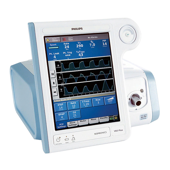
General information Ventilator unit Depending on the version of the ventilator you have, the Accept button on the upper-right front of the device may or may not be surrounded by a navigation ring (scrollable wheel). Newer versions have a streamlined appearance and the Accept button, and look like this: Accept button Legacy versions have both the navigation ring and Accept button, and look... - Page 35 General information Key panel Figure 3-3: Front view Number Description Graphical user interface. Color LCD (liquid crystal display) with touchscreen. Accept button. Activates selections. Proximal pressure port. Connection for tubing that monitors patient pressure in the patient circuit. Ventilator outlet (To patient) port. Main connection for the patient circuit. Deliv- ers air and oxygen in prescribed pressures to the patient.
- Page 36 General information Figure 3-4: Side view Number Description Ventilation vents. Allow intake of air for delivery to the patient. Air inlet filter (under side panel). Filters the air for delivery to the patient.
- Page 37 General information 5 4 3 2 Figure 3-5: Rear view Number Description Backup battery (compartment under side panel). Remote alarm/nurse call connector Reserved for future use Power cord retainer Power cord RS-232 serial connector (female DB-25). Connects to hospital information systems and other serial devices.
-
Page 38: About The Backup Battery
General information About the backup WARNING: To reduce the risk of power failure to the ventilator, pay close attention to the battery’s charge level. The battery’s operation time is approximate and battery is affected by ventilator settings, discharge and recharge cycles, battery age, and ambient temperature. - Page 39 General information CAUTION: Avoid allowing the ventilator battery to become completely discharged. Otherwise, the battery may become over-discharged and require long recharge times of up to 16 hours or more. The over- discharged condition may permanently damage the battery so that it is unable to recharge.
-
Page 40: About The Graphical User Interface
General information About the graphical Through the graphical user interface (Figure 3-7) you make ventilator settings and view ventilator and patient data. During ventilation, the upper screen user interface displays alarms and patient data. The middle screen displays real-time waveforms and alarm and informational messages. The lower screen lets you access modes and other ventilator settings, display help information, and see the power status. -
Page 41: Navigating The Graphical User Interface
General information Navigating the graphical user interface Select a function by touching the desired tab or button on the touchscreen. If your ventilator has only the Accept button on the top-right front of the device (newer versions), you adjust values and navigate the graphical user interface by using the touchscreen. - Page 42 General information Adjustment Slider flag Setting range scale arrow button Proposed value The navigation ring (on legacy versions) also lets you adjust the position of the cursor in the waveforms window while the screen is frozen. See "Freezing and unfreezing waveforms" on page 8-3 for more information. 3-14...
-
Page 43: Starting Up The Ventilator
ON/Shutdown key, then the Accept button on the top-right front of the ventilator. Training Product training is available. Contact your local Philips sales representative or Philips Customer Support for assistance. Call 1-800-225-0230 for ordering and 1-800-722-9377 for service. - Page 44 General information 3-16...
- Page 45 Chapter 4. Principles of operation System operational The Respironics V60/V60 Plus Ventilator is a microprocessor-controlled pneumatic system that delivers a mixture of air and oxygen. It is powered by overview AC with battery backup to protect against power failure or unstable power and to facilitate intrahospital transport.
-
Page 46: Principles Of Operation
CO removal. Breath delivery Control variable Breaths delivered by the Respironics V60/V60 Plus Ventilator are pressure characteristics controlled. In the AVAPS mode, the ventilator’s applied pressure is automatically adjusted over a period of time to maintain a target tidal volume. -
Page 47: Pressure Rise Time
Auto-Trak Sensitivity An important characteristic of the Respironics V60/V60 Plus Ventilator is its ability to recognize and compensate for intentional and unintentional leaks in the system, and to automatically adjust its triggering and cycling algorithms to maintain optimum performance in the presence of leaks. - Page 48 Principles of operation Shape signal method of cycling and triggering. The shape signal or “shadow trigger” method uses a mathematical model derived from the flow signal. A new flow signal (shape signal) is generated by offsetting the signal from the actual flow and delaying it (Figure 4-2).
-
Page 49: Leak Adaptation
Principles of operation Leak adaptation Noninvasive ventilation in particular may involve considerable leakage around the mask or through the mouth. Some leakage is known or intentional: it is a characteristic of the mask/patient interface design. So that it can accurately adjust its baseline flow, the ventilator has you enter the intentional leakage value specific to the mask/patient interface (“Selecting the mask and exhalation port”... -
Page 50: Auto-Trak+ (Optional)
Volume adjustment Figure 4-5: Tidal volume adjustment Auto-Trak+ (optional) The Auto-Trak+ option for the Respironics V60/V60 Plus Ventilator lets you further adjust the level of Auto-Trak Sensitivity, a feature that recognizes and compensates for intentional and unintentional leaks. This algorithm has multiple breath trigger and cycle thresholds. -
Page 51: Ventilation Modes
Patient alarms are not available during high flow therapy. This therapy is not considered a breath delivery mode. HFT requires 3.00 software and above. Ventilation modes The Respironics V60/V60 Plus Ventilator operates in the following ventilation modes: • CPAP (continuous positive airway pressure) mode •... -
Page 52: Cpap Mode
Principles of operation CPAP mode In the CPAP (continuous positive airway pressure) mode, the ventilator functions as a demand flow system, with the patient triggering all breaths and determining their timing and size. The patient triggers and cycles based on the ventilator’s Auto-Trak Sensitivity algorithms. -
Page 53: Pcv Mode
Principles of operation PCV mode The PCV (pressure-controlled ventilation) mode delivers pressure-controlled breaths, either triggered by the ventilator (Timed) or the patient (Spont). The control settings active in the PCV mode are shown in Figure 4-8. The IPAP setting defines the applied inspiratory pressure for all breaths. If the patient fails to trigger a breath through Auto-Trak within the interval determined by the rate setting, the ventilator triggers a mandatory breath. -
Page 54: S/T Mode
Principles of operation S/T mode The S/T (spontaneous/timed) mode guarantees breath delivery at the user-set rate. It delivers pressure-controlled, time-cycled mandatory and pressure- supported spontaneous breaths, all at the IPAP pressure level. If the patient fails to trigger a breath within the interval determined by the Rate setting, the ventilator triggers a mandatory breath with the set I-Time. -
Page 55: Avaps Mode
Principles of operation AVAPS mode NOTE: When you adjust AVAPS minimum and maximum pressures, remember that IPAP is adjusted to meet the target value. If the calculated target pressure is outside of the minimum and maximum pressure range, the target volume will not be achieved. Unlike most pressure modes, the AVAPS (average volume-assured pressure support) mode delivers a target tidal volume. - Page 56 Principles of operation Max P Mandatory (Timed) Rise breath Min P EPAP I-Time Patient-triggered (Spont) 1/Rate spontaneous breath Time Figure 4-13: AVAPS waveforms 4-12...
-
Page 57: Ppv Mode (Optional)
Principles of operation PPV mode (optional) The PPV (proportional pressure ventilation) mode provides patient-triggered breaths that deliver pressure in proportion to patient effort. Additionally a user- settable backup rate activates machine-triggered, pressure-limited, and time- cycled breaths in the case of apnea. In the PPV mode, patient effort determines the pressure, flow, and tidal volume delivered by the ventilator. - Page 58 Principles of operation setting. If the patient fails to trigger a breath within the interval determined by the Rate control, the ventilator triggers a Timed (backup) breath with the set I-Time, Rise, and IPAP settings. The control settings active in the PPV mode are shown in Figure 4-14. Figure 4-14: PPV controls Figure 4-15 shows PPV mode waveforms.
-
Page 59: Oxygen Mixing
Principles of operation Oxygen mixing The ventilator’s oxygen mixer regulates and proportions oxygen into the air from the blower according to the O setting. The delivered oxygen accuracy is ±5% of the set value up to the maximum oxygen flow available. The ventilator can deliver up to 240 L/min of air/oxygen mix to assist in managing uncontrolled leaks during noninvasive ventilation. - Page 60 Principles of operation 4-16...
-
Page 61: Setting Up The Ventilator For Use
The Analytical Industries 2000M monitor includes user-settable high and low oxygen % alarms and is approved for use with the V60/V60 Plus Ventilator. Refer to the monitor instructions for use for detailed instructions on the proper setup and operation of the oxygen monitor. -
Page 62: Connecting To Ac Power
WARNING: To prevent unintentional disconnection of the power cord, always use the correct, Philips-supplied power cord and lock it into place with the power cord retainer before you switch the ventilator on. The retainer is designed to hold the connector end of the Philips-supplied cord securely in place. -
Page 63: Installing The Patient Circuit
Install the patient circuit as shown in this section. For a list of compatible parts and accessories offered by Philips, see “Parts and accessories” on page C-1. -
Page 64: Installing The Nebulizer
Setting up the ventilator for use Assemble the patient circuit, including the main flow (inspiratory) bacteria filter, proximal pressure line, oxygen sensor tee, and if desired, humidifier and nebulizer. Figure 5-1 shows the circuit configuration for noninvasive ventilation or high flow therapy. - Page 65 Setting up the ventilator for use NOTE: This circuit setup is recommended for noninvasive ventilation. It is also recommended for high flow therapy when using the AC611 high flow nasal cannula with FEP Connector to block the exhalation port. Proximal pressure port Ventilator...
- Page 66 Setting up the ventilator for use NOTE: This circuit setup is recommended for noninvasive ventilation. Proximal pressure port Ventilator outlet Oxygen sensor tee Bacteria filter Proximal pressure line Figure 5-2: Noninvasive patient circuit, without humidification...
-
Page 67: Connecting External Devices
The Respironics V60/V60 Plus Ventilator can communicate with a Philips patient monitor using the IntelliBridge Open Interface. See “Using Philips monitors and the IntelliBridge or VueLink Open Interfaces” on page B-2. The ventilator also supports the VueLink Open Interface. -
Page 68: Before Placing A Patient On The Ventilator
Setting up the ventilator for use Before placing a WARNING: To ensure the ventilator’s safe operation, always verify ventilator operation as described in “Verify ventilator operation” on page 5-8 before patient on the using the ventilator on a patient. If the ventilator fails any tests, remove it ventilator from clinical use immediately. -
Page 69: Running Alarm Tests
Setting up the ventilator for use d. VERIFY that the blue “Running on Internal Battery” message is displayed. 6. Install a fully-charged battery and reconnect the ventilator to AC power. 7. Repeat step 5 to verify that the ventilator switches over to battery power. -
Page 70: Low Tidal Volume
Setting up the ventilator for use Low Tidal Volume 1. Raise the Lo V alarm setting above the displayed, measured V 2. VERIFY that the alarm is activated. Low Tidal Volume 3. Turn the Lo V alarm setting OFF. 4. VERIFY that the alarm resets. Patient Disconnect 1. -
Page 71: Using The Ventilator For Intra-Hospital Transport
WARNING: The V60/V60 Plus Ventilator requires a pressurized oxygen supply that provides a minimum flow of 175 SLPM. Do not use any devices such as valves, hoses, Grab n' Go regulators or other brands of combined cylinder/ regulators that limit supply of oxygen flow below 175 SLPM. - Page 72 Setting up the ventilator for use 95 100 Leak of 10 L/min Leak of 20 L/min Leak of 30 L/min Leak of 40 L/min Leak of 50 L/min a. V = 500 mL, Rate = 40 BPM, EPAP = 6 cmH O, IPAP = 18 cmH 95 100 Leak of 20 L/min...
-
Page 73: Storing The Ventilator Between Patient Use
MRI safety WARNING: The V60/V60 Plus Ventilator is MR Unsafe. Keep it outside the MRI scan room (Zone IV). It represents a projectile hazard. information Security and Privacy To develop a security strategy related to the use of the ventilator, refer to the Hospital Respiratory Care product security guide. - Page 74 Setting up the ventilator for use 5-14...
-
Page 75: Operation
Chapter 6. Operation WARNING: To ensure the ventilator’s safe operation, always verify ventilator operation as described in “Verify ventilator operation” on page 5-8 before using the ventilator on a patient. If the ventilator fails any tests, remove it from clinical use immediately. Do not use the ventilator until necessary repairs are completed and all tests have passed. -
Page 76: Changing The Mode
Operation Changing the mode The active ventilation mode is displayed in the bottom, left-hand corner of the screen. Change the mode as follows. For details on modes, see “Ventilation modes” on page 4-7. 1. Open the Modes window. 2. Select the desired mode. Active mode 3. -
Page 77: Changing Control Settings
Operation Changing control Table 6-3 on page 6-23 is an alphabetical list of the control settings with their ranges. Table 11-2 on page 11-2 shows the control settings applicable to the settings different modes. For more information on control settings as they apply in the different ventilation modes, see “Ventilation modes”... -
Page 78: Changing Individual Ventilator Settings
Operation Changing individual ventilator settings You can make ventilator settings from the Settings window. 1. Open the Settings window. 2. Select the desired setting. As an example we will show the IPAP adjustment. 3. The setting window opens. Adjust the setting. Select Accept to apply. Adjustment Setting range scale arrow button... -
Page 79: Using The Ramp Time Function
Operation Using the Ramp Time The Ramp Time function helps your patient adapt to ventilation by gradually increasing inspiratory and expiratory pressure (IPAP and EPAP/CPAP) from function subtherapeutic to user-set pressures over a user-set interval. Table 6-3 on page 6-23 describes this function’s principles of operation. Follow these instructions to use the Ramp Time function: 1. -
Page 80: Using The 100% O Function
Operation Using the 100% O NOTE: The 100% O feature is available in Revision 2.30 software and above. function The 100% O function delivers 100% oxygen to the patient. It is available during Screen Lock status. Follow these instructions to use the 100% O function: 1. -
Page 81: Using Ppv
Operation Using PPV Follow these instructions to set up the ventilator in the PPV mode, referring to Figure 6-3. For principles of operation, see “PPV mode (optional)” on page 4-13. 1. Open the PPV Settings window. 2. Set EPAP, O , alarm limits, and backup settings to appropriate values. - Page 82 Operation Max V Inspiration terminated Max V Sudden increase in flow Time Figure 6-1: PPV waveform – Max V limit When the Max P (PPV maximum pressure limit) is reached, pressure is limited but the breath is not terminated, and a message is displayed. After the limit is reached in three consecutive breaths, the audible alarm sounds.
-
Page 83: Guidelines For Using Ppv
Operation Guidelines for using PPV NOTE: The guidelines below are based on recommendations by clinicians. They do not replace the clinical judgment of a physician and should not, on their own, be used for clinical decision making. Determining Max R and Max E settings It is recommended you set Max R (flow assist) and Max E (volume assist) to initial values and then titrate them based on the patient’s disease process: •... - Page 84 Operation 2. Adjust Max E: a. Evaluate the patient. Check whether any of these conditions is true: • The patient says they are getting too much air, pressure, or volume • The patient is using accessory muscles to actively stop inspiration •...
- Page 85 Operation Start Max R Make initial settings: titration EPAP: 4 cmH : Current setting or per prescription Max P: 25 cmH Max V: 1000 to 1500 mL Does the patient say the air PPV %: 80 to 100% is coming too fast ? Max E: 5 cmH Max R: 2 cmH O/L/s...
-
Page 86: Changing Alarm Settings
Operation Changing alarm WARNING: To prevent possible patient injury, avoid setting alarm limits to extreme values, which can render the alarm system useless. settings Some ventilator alarm settings are operator adjustable. You can adjust these at any time. Table 6-4 on page 6-26 lists the alarm settings and their ranges. Review and adjust the alarm settings as follows: 1. - Page 87 Description ET/Trach ET or tracheostomy tube Leak 1 Mask with minimal intentional leak characteristics. En- ter Leak 1 for any of these Philips Respironics masks: • Contour Deluxe nasal mask • PerformaTrak mask • AF531, AF541 (EE) Leak 2 Mask with medium intentional leak characteristics. En- ter Leak 2 for this mask: •...
- Page 88 Not allowed with current mask is displayed. NOTE: In ventilation modes, ET/tracheostomy tubes and most Philips Respironics masks require the use of an exhalation port. If you selected ET/Trach or Leak 1 as a mask/patient interface, you may not select None as an exhalation port.
- Page 89 Philips Respironics Disposable Exhalation Port Whisper Swivel Philips Respironics Whisper Swivel Philips Respironics Plateau Exhalation Valve Other Exhalation port not supplied by Philips Respi- ronics. None No inline circuit exhalation port NOTE: If you select None, refer to the manufacturer’s instructions to make sure the mask selected contains an exhalation port.
-
Page 90: Running The Exhalation Port Test
Operation Running the The exhalation port test is required and its window is automatically displayed when PEV or Other is selected. exhalation port test Procedure Run the test as follows: 1. Disconnect the patient circuit from the mask/patient interface. 2. Occlude the circuit outlet. Select Start Test. 3. -
Page 91: Troubleshooting
Operation 5. Reconnect the patient circuit to the mask/interface. 6. Select Start Ventilation to initiate ventilation. Troubleshooting If Test Failed is displayed, check for leaks in the patient circuit, and install an exhalation device with lower leak characteristics. Repeat test. If the exhalation port test fails again, the intentional leak is unknown and Tot.Leak rather than Pt. -
Page 92: Mask/Port
Operation Mask/Port See “Selecting the mask and exhalation port” on page 6-12. Vent Info (ventilator information) The Ventilator Information window displays software version and other information specific to your ventilator. Screen Lock Screen Lock deactivates all buttons and tabs on the touchscreen except Alarm Silence, Alarm Reset, the Alarm/Message button, and Help. - Page 93 Operation 2. Select the desired adjustment. As an example, the E-Cycle adjustment is shown below. 3. The setting window opens. Adjust the setting, referring to the pressure-time graphic which represents the effect on I-Time. Select Accept to apply. Proposed value When Auto-Trak+ is active (when either Trigger or E-Cycle is set to a value other than Normal), the ventilator setting window displays Auto-Trak+.
-
Page 94: Standby
Operation Standby Standby lets you safely suspend ventilation to temporarily disconnect the patient from the ventilator or to set up the ventilator before connecting the patient. Alarms are disabled during standby. You can also change ventilator settings and most menu functions during standby. - Page 95 Operation 2. Disconnect the patient from the ventilator now. The ventilator enters standby and displays the Standby screen. 3. To resume ventilation, reconnect the patient. When the ventilator senses a patient breathing effort, ventilation automatically resumes in the previous mode. NOTE: You can also manually resume ventilation with the Restart Mode button.
-
Page 96: Help Function
Operation Help function Select the help button to display additional information. Help messages are displayed: Help message 6-22... -
Page 97: Table Of Modes And Control Settings
Operation Table of modes and control settings Table 6-3: Modes and control settings with ranges Setting Description Range Modes Modes Ventilation mode AVAPS, CPAP, S/T, PCV Optional: PPV Control settings C-Flex Enhances traditional CPAP by reducing the OFF, 1 to 3 Pressure relief pressure at the beginning of exhalation––a time when patients may be uncomfortable... - Page 98 Operation Table 6-3: Modes and control settings with ranges (continued) Setting Description Range I-Time (Inspira- Time to deliver the required gas. Inverse ra- 0.30 to tory Time) tio ventilation is not allowed. 3.00 secs Resulting I:E Shows where I:E ratio ratio becomes inverse Max E...
- Page 99 Operation Table 6-3: Modes and control settings with ranges (continued) Setting Description Range Min P (AVAPS The minimum pressure to be applied. 5 to 30 cmH Minimum IPAP Pressure) NOTE: When you adjust the AVAPS minimum and maximum pressures, remember that IPAP is adjusted to meet the target value.
- Page 100 Operation Table 6-3: Modes and control settings with ranges (continued) Setting Description Range Trigger Trigger Sensitivity. Auto-Trak+ employs several algorithms to determine the point at which Normal, +1 to (optional) the inspiration begins. The larger the value, the more sensitive the trigger (that is, the pa- tient can trigger inspiration with less effort).
- Page 101 Operation Table 6-4: Alarm settings (continued) Setting Description Range NOTE: In the S/T and PCV modes, the LIP alarm should be set 3-5 cmH O below the IPAP level. When set in this manner, the alarm works in conjunction with the LIP T alarm to indicate if there is a failure to trigger between the two pressure levels.
- Page 102 Operation 6-28...
- Page 103 Chapter 7. High flow therapy The high flow therapy (HFT) feature is available for 3.00 software and above, as well as V60 Plus. HFT is accessed from the Standby mode. For more information, see “Standby” on page 6-20. For principles of operation, see “High flow therapy” on page 4-6.
-
Page 104: High Flow Therapy
High flow therapy High flow nasal Use either the AC611 high flow nasal cannula with FEP Connector (Figure 7-1) or the AC611 high flow nasal cannula 22 mm (Figure 7-3), which connects cannula setup directly to the patient circuit. Using the FEP Connect for high flow therapy NOTE: This section applies only if you are using the AC611 high flow nasal cannula with filter exhalation port (FEP) connector (“FEP Connect”) -
Page 105: Changing From Ventilation To High Flow Therapy (Hft)
High flow therapy Proximal pressure port Proximal pressure line Tubing clips Figure 7-2: Proximal pressure line anchored to circuit with tubing clips Changing from ventilation to high flow therapy (HFT) Follow the instructions in this chapter. Immediately after starting HFT disconnect the proximal pressure line from the ventilator. -
Page 106: Connecting Directly To A 22 Mm Circuit
22 mm connector Figure 7-3: High flow nasal cannula, 22 mm connection Changing from an NIV Follow these instructions to use the V60/V60 Plus Ventilator for high flow therapy (HFT). mode to high flow therapy 1. -
Page 107: Viewing And Pausing The Hft Graph
High flow therapy 5. From the Active Mode window, you can adjust Flow and O 6. Press Start HFT. 7. The High Flow Therapy Active message is displayed during HFT. 8. Apply the HFT interface to the patient. 9. Note the low priority alarm stating that patient alarms are disabled during HFT. -
Page 108: Changing From High Flow Therapy To An Niv Mode
2. Select Standby to open the Standby window. 3. Press the Enter Standby button. 4. In the Select Therapy window, press Ventilation. 5. Replace the high flow patient interface with a Philips-approved NIV mask. 6. Review patient settings and alarms. - Page 109 High flow therapy Table 7-1: HFT Alarm and other messages: summary and troubleshooting Priority Manually Autores Silence Message Description Corrective Action type (ID) resettable ettable able Cannot Reach Target Displays when HFT (high Check the patient. Check Flow flow therapy) is active. In- that the high flow nasal (66) dicates that flow target is...
- Page 110 High flow therapy...
-
Page 111: Patient Monitoring
Chapter 8. Patient monitoring The ventilator displays numeric patient data in the patient data window and real-time graphics in the waveform window (Figure 8-1). Numeric patient data is updated every breath. Table 8-1 on page 8-2 lists the ventilator’s monitored parameters. -
Page 112: Table Of Monitored Parameters
Patient monitoring Table of monitored parameters Table 8-1: Monitored parameters Parameter Definition Patient data window Breath phase/trigger indicator Spont (spontaneous): Inspiratory phase, patient-triggered breath (color: turquoise) Timed: Inspiratory phase, ventilator-triggered breath (color: orange) Exhale: Expiratory phase (color: blue) Peak inspiratory pressure. The highest patient pressure during the previous breath cycle. Pt. -
Page 113: Freezing And Unfreezing Waveforms
Patient monitoring Freezing and Freeze waveforms for extended viewing by selecting the pause button to the left of the waveform window. unfreezing waveforms The cursor makes one complete sweep across the waveform and then displays the pause in progress symbol. The graphic display is then frozen, and the cursor is visible in the middle of the display (Figure 8-2). - Page 114 Patient monitoring...
- Page 115 NOTE: If an alarm persists for no apparent reason, discontinue ventilator use and contact Philips. Respond to an alarm as follows: 1. Approach the patient immediately. Secure sufficient and effective ventilation for the patient. You may silence the alarm if possible.
-
Page 116: Alarms, Messages, And Troubleshooting
Alarms, messages, and troubleshooting Alarm status bar (nonalarm status) No active alarms Alarm Reset Alarm button button (active) (active) Up arrows indicate that you can hide message in Alarms/ Messages list Alarm status bar Alarm Silence (active alarm status) button (active) Autoreset alarm (strikeout line through message) Waveforms... - Page 117 Alarms, messages, and troubleshooting Table 9-1: Alarm summary Alarm LED on front Alarm message in Remote Status panel Alarm status bar Alarms list Audio Action required alarm No alarms None None Autoreset Red (high- Background color alarm priority) or yellow same as that of (low-priority) active alarm.
-
Page 118: Setting Alarm Loudness
Alarms, messages, and troubleshooting Figure 9-2: Vent Inoperative screen Setting alarm You can set the alarm loudness from the Menu window (see “Loudness” on page 6-17). loudness... -
Page 119: Silencing Alarms
Alarms, messages, and troubleshooting Silencing alarms Silence an alarm for 2 minutes by selecting the Alarm Silence button. The button icon is replaced by this one. A timer shows time remaining in the 2-minute alarm silence period. Select Alarm Silence again at any time to reset the counter to 2:00 minutes. During patient maneuvers, you can pre-silence audible alarms as desired. -
Page 120: Hiding/Displaying Alarm Messages
Alarms, messages, and troubleshooting Hiding/displaying To hide an alarm or informational message in the Alarms or Messages list, touch the flashing alarm indicator button or informational message button alarm messages when up arrows are present. To display messages, touch the flashing alarm indicator or Informational Message button when down arrows are present. -
Page 121: Alarms And Other Messages
Alarms, messages, and troubleshooting Alarms and other Table 9-3 is a list of alarms and other messages displayed by the ventilator, along with descriptions, suggested corrective actions, and other information. messages The ID (identifier) listed with the priority type is the priority number of the alarm. - Page 122 Alarms, messages, and troubleshooting Table 9-3: Alarm and other messages: summary and troubleshooting (continued) Priority Manually Autores Silence Message Description Corrective Action type (ID) resettable ettable able High Rate Measured respiratory rate Check the patient. Con- Low/ is greater than the Hi Rate firm ventilator and alarm High setting.
- Page 123 Alarms, messages, and troubleshooting Table 9-3: Alarm and other messages: summary and troubleshooting (continued) Priority Manually Autores Silence Message Description Corrective Action type (ID) resettable ettable able Low Minute Ventila- Estimated minute ventila- Check the patient. Con- • tion tion is less than the Lo firm ventilator and alarm (56) setting.
- Page 124 Alarms, messages, and troubleshooting Table 9-3: Alarm and other messages: summary and troubleshooting (continued) Priority Manually Autores Silence Message Description Corrective Action type (ID) resettable ettable able Oxygen Not Available Oxygen supply pressure Check the patient. Check High out of range, oxygen de- if high/low O source is (47)
- Page 125 Alarms, messages, and troubleshooting Table 9-3: Alarm and other messages: summary and troubleshooting (continued) Priority Manually Autores Silence Message Description Corrective Action type (ID) resettable ettable able Power has been re- Power is restored follow- Check the patient. Con- Infor- stored ing loss of power.
- Page 126 Alarms, messages, and troubleshooting Table 9-3: Alarm and other messages: summary and troubleshooting (continued) Priority Manually Autores Silence Message Description Corrective Action type (ID) resettable ettable able Proximal Pressure Proximal pressure low for Check the patient. Recon- High Line Disconnect a few seconds.
- Page 127 Alarms, messages, and troubleshooting Table 9-4: Check Vent alarm messages: summary and troubleshooting (continued) Priority Manually Autores Silence Message Description Corrective Action type (ID) resettable ettable able Check Vent: 35 V Technical failure Check the patient. Provide High Supply Failed alternative ventilation.
- Page 128 Alarms, messages, and troubleshooting Table 9-4: Check Vent alarm messages: summary and troubleshooting (continued) Priority Manually Autores Silence Message Description Corrective Action type (ID) resettable ettable able Check Vent: Blower Technical failure Check the patient. Provide High Stalled alternative ventilation. Have the ventilator serviced.
- Page 129 Alarms, messages, and troubleshooting Table 9-4: Check Vent alarm messages: summary and troubleshooting (continued) Priority Manually Autores Silence Message Description Corrective Action type (ID) resettable ettable able Check Vent: Ma- Proximal pressure is Check the patient. Provide High chine Pressure Sen- not measured.
- Page 130 Alarms, messages, and troubleshooting Table 9-4: Check Vent alarm messages: summary and troubleshooting (continued) Priority Manually Autores Silence Message Description Corrective Action type (ID) resettable ettable able Check Vent: Proximal Proximal pressure is Check the patient. Provide High Pressure Sensor not measured.
- Page 131 Alarms, messages, and troubleshooting Table 9-5: Vent Inoperative alarm messages: summary and troubleshooting (continued) Priority Manually Autores Silence Message Description Corrective Action type (ID) resettable ettable able Vent Inoperative Technical failure of the Check the patient. Provide al- High 1005 motor PCBA.
- Page 132 Alarms, messages, and troubleshooting 9-18...
- Page 133 Disinfection is most effective on medical devices that were previously cleaned. NOTE: For all V60/V60 Plus hardware accessories recommended by Philips, follow the cleaning and disinfection guidelines in this chapter. For multi-patient interface and circuit accessories, consult the product instructions for use. For single patient use accessories, no cleaning and disinfection is needed.
-
Page 134: Care And Maintenance
Care and maintenance Exterior and CAUTION: To prevent possible damage to the ventilator, use only those cleaning and disinfecting agents listed in this manual. touchscreen cleaning CAUTION: To prevent possible damage to the ventilator, do not drip or spray any liquids directly onto any surface including the front panel, touchscreen, navigation ring (legacy versions), and Accept button. -
Page 135: Exterior And Touchscreen Disinfection
Care and maintenance Exterior and CAUTION: To prevent possible damage to the ventilator, use only those cleaning and disinfecting agents listed in this manual. touchscreen CAUTION: To prevent possible damage to the ventilator, do not drip or spray any disinfection liquids directly onto any surface including the front panel, touchscreen, navigation ring (legacy versions), and Accept button. -
Page 136: Bacteria Filter, Patient Circuit, And Other Accessories
Care and maintenance Bacteria filter, patient Follow the manufacturer’s instructions that accompany the accessory. circuit, and other accessories WARNING: To prevent patient or ventilator contamination, inspect and replace the main flow bacteria filter between patients and at regular intervals (or as stated by the manufacturer). -
Page 137: Preventive Maintenance
Failure to do so may result in electric shock. The expected service life of your V60/V60 Plus ventilator is 10 years. Perform preventive maintenance on the ventilator according to the schedule in Table 10-2. You can view the hours of ventilator operation in the Vent Info window (“Vent Info (ventilator information)”... -
Page 138: Replacing The Air Inlet Filter
Care and maintenance Replacing the air inlet filter Replace the air inlet filter as follows, referring to Figure 10-1. 1. Power down the ventilator and disconnect it from AC power. Remove ventilator from cart, if applicable. 2. Turn the captive D-ring fastener counter-clockwise one-quarter turn and release. -
Page 139: Cleaning Or Replacing The Cooling Fan Filter
Care and maintenance Cleaning or replacing the cooling fan filter Clean or replace the cooling fan filter as follows, referring to Figure 10-2: 1. Insert a small, flat blade driver tip between the foam filter and the filter retaining cover (Figure 10-2). 2. -
Page 140: Removing And Replacing The Battery
(for example, oxygen cell, batteries). Dispose of this device in accordance with local collections and recycling regulations. For more information, visit www.philips.com/recycling. This device contains a lithium ion battery that cannot be recycled. Please contact customer service for safe disposal instructions of this part. -
Page 141: Service And Repairs
If necessary, Philips will send you a battery return kit that contains a prepaid postal label and instructions for returning the battery if it has failed prematurely (within 5 years of its manufacture date). The order number for the return kit is 989805663471 / part number 1146145. - Page 142 Care and maintenance 10-10...
-
Page 143: Technical Specifications
4 cmH target) Flow 10 to 80 L/min 5 L/min 35 L/min (High flow therapy, 3.00 software and above, and V60 Plus) IPAP 4 to 40 cmH 1 cmH ± (2 cmH O + 4% of 12 cmH target) I-Time (Inspiratory 0.30 to 3.00 sec... - Page 144 Rise (Rise Time) 1 to 5 (AVAPS Target Tidal 200 to 2000 mL BTPS 5 mL ± 15% 500 mL Volume) Table 11-2: Controls active in Respironics V60/V60 Plus ventilation modes CPAP AVAPS Timing Rate Rate I-Time I-Time* Baseline pressure...
-
Page 145: Patient Data
Technical specifications Patient data Table 11-3: Patient data ranges, resolutions, and accuracies during ventilation Parameter Range Resolution Accuracy Patient data window Breath phase/trigger indicator Spont, Timed, Exhale Color-coded display: Spont - turquoise, Timed - orange, Ex- hale - blue 0 to 50 cmH 1 cmH ±... -
Page 146: Alarms
Loudness 1 to 10 Mask/ET Selection ET/Trach, 1, 2, 3, 4, Other Exhalation Port Selection • FEP (Philips Respironics Filtered Exhalation Port) • DEP (Philips Respironics Disposable Exhalation Port • Whisper Swivel (Philips Respironics Whisper Swivel), • PEV (Philips Respironics Plateau Exhalation Valve), •... -
Page 147: Diagnostic Mode Functions
Technical specifications Diagnostic mode Table 11-6: Diagnostic mode functions functions Function Range Language English, Nederlands, Français, Deutsch, Italiano, Por- tuguês, Español, Dansk, Suomi, Norsk, Svenska, Chi- nese, Japanese, Türkçe Date/Time Pressure Units O, hPa Restore Default Settings Software Options Baud Rate 9,600, 19,200, 115,200 Alarm Volume Escalation Enable, Disable (default) -
Page 148: Physical Characteristics
12 kg (26 lb) with battery V60/V60 Plus ventilator in its most usual configuration Installed weight V60/V60 Plus Ventilator with backup battery, ventila- tor stand, O tank holder, two E-cylinders (full), two (V60/V60 Plus ventilator on gauge clusters, oxygen analyzer with mount, humidifi-... -
Page 149: Pneumatic Specifications
Pressure: 3.31 to 6.00 bar / 331 to 600 kPa / 48 to 87 psig Flow: 175 SLPM High-pressure oxygen supply Connector: DISS male, DISS female, NIST (using V60/V60 Plus manifold) Pressure: 3.10 to 6.00 bar / 310 to 600 kPa / 45 to 87 psig Flow: 175 SLPM Connector: SIS Pressure: 3.66 to 6.00 bar / 366 to 600 kPa / 53 to... -
Page 150: Electrical Specifications
Technical specifications Electrical specifications Table 11-10: Electrical specifications Parameter Specification AC voltage 100 to 240 VAC AC frequency 50/60 Hz AC power 300 VA Battery PN 1076374: 14.4 V, 11.0 Ah, 163 Wh Maximum system current draw: 11 A Charge voltage: +16.9 V maximum Operating time: 360 minutes (6 hours) under normal conditions Accessory... -
Page 151: Alarm-Related Specifications
Technical specifications Alarm-related specifications Table 11-12: Alarm-related specifications Parameter Specification Delay time from the onset of the < 10 ms from onset of the alarm condition to the alarm condition to the point that transmission of the signal the representation of the alarm <... - Page 152 Parameter/Characteristic Specification High flow therapy 10 to 80 L/min BTPS (3.00 software and above, and V60 Plus) NOTE: The maximum deliverable flow rate varies based on the orifice size of the nasal cannula and on the patient’s nasal passage resistance.
- Page 153 Inspect the front panel for inspection scratches or abrasions. Correct and/or report any problems found to Philips before using the ventilator. Before using the ventilator the first time, we recommend wiping the exterior...
-
Page 154: First-Time Installation
Ensure that the locking lever on the back right of the stand locks into place. Figure A-1: Mounting the V60/V60 Plus Ventilator on the stand... - Page 155 Figure A-2 shows the installed ventilator. Use the brakes to lock and unlock the wheels as needed. Make sure the wheels are unlocked before moving the ventilator. Power cords can be stored on stand hooks Wheel lock Figure A-2: Respironics V60/V60 Plus Ventilator on stand...
-
Page 156: Installing The Battery
3. Using a 3-mm hex wrench, remove the battery bracket by removing two screws. 4. Holding the battery so that the vent hole faces up and the Philips logo faces out, thread the battery cable through the battery bracket. Position and place the battery inside the battery compartment. - Page 157 Following battery installation, if a Check Vent or Vent Inoperative alarm occurs when verifying ventilator operation, discontinue use of the ventilator immediately and contact Philips. The Vent Inoperative alarm occurs if AC power is disconnected and a battery is not installed, or if the battery is fully discharged.
- Page 158 First-time installation Captive fastener Bracket Battery Orient with vent hole on top and Philips logo facing out Battery cable Figure A-3: Installing the battery...
-
Page 159: Installing Oxygen Inlet Connector And Ac Power Cord
First-time installation Installing oxygen The Respironics V60/V60 Plus Ventilator destined for Japan, China, and the USA are typically pre-configured. V60/V60 Plus Ventilators shipped to other inlet connector and countries may require installation of the power cord and oxygen inlet AC power cord connector. - Page 160 Philips-supplied cord securely in place. WARNING: The V60/V60 Plus Ventilator should not be positioned in a way that makes it difficult to disconnect from mains power if necessary. Disconnect from supply mains by removing the power cord from the wall outlet. The AC mains plug is used as disconnection device.
-
Page 161: Installing The Oxygen Manifold Kit
First-time installation Installing the oxygen If desired, install the oxygen manifold kit as described in the accompanying instructions. manifold kit Verifying ventilator Perform the following steps to verify ventilator and audible alarm operation: operation and audible 1. Assemble and install a patient circuit. (See Chapter 5 for instructions alarm on installing a patient circuit.) 2. - Page 162 First-time installation A-10...
-
Page 163: Communications Interface
Also be aware that local laws may take priority over the above mentioned requirements. If in doubt, consult Philips. WARNING: The USB port is not currently available for use. DO NOT connect or attempt to power any equipment from the USB port. -
Page 164: Rs-232 Serial Port
• Legacy (VRPT/SNDA): Fixed text-based protocol (not to be used for developing new driver interfaces). For this protocol specification, refer to the V60 Communications interface VRPT / SNDA Developers Guide (1147828MC), available at www.philips.com/IFU. Using Philips Using Philips monitors and the IntelliBridge or VueLink Open Interfaces... -
Page 165: Data Display
Figure B-3: Connection from ventilator to Philips patient monitor Data display The data from your Respironics V60/V60 Plus Ventilator is displayed in several windows on your Philips monitor. This data may be labeled differently on the monitor than on the ventilator. Refer to Table B-1 to interpret these labels. - Page 166 Communications interface Table B-1: Ventilator data displayed on Philips monitor (continued) Monitor label Ventilator label Modes Same as ventilator mode name All modes except standby STNDBY Standby Control settings sEppv Max E Not shown C-Flex PAVsup PPV % sCPAP CPAP...
-
Page 167: Remote Alarm Port
Communications interface Table B-1: Ventilator data displayed on Philips monitor (continued) Monitor label Ventilator label LOW EXH MV Low Minute Ventilation LOW O2 SUPPLY Low O Supply Pressure LOW RESP RATE Low Rate LOW EXH TV Low Tidal Volume NO O2 SUPPLY... - Page 168 For ¼” jack. Remote alarm cable kit, Use on Normally Opened nurse call systems (system expects to 1003742 alarm state = closed see closed contacts when ventilator alarms). For ¼” jack. Remote alarm cable kit Philips Respironics (LifeCare) 1003743...
- Page 169 For the most current list of approved accessories plus comprehensive ordering information for compatible parts available from Philips, contact your Philips representative or refer to the V60/V60 Plus ordering and accessories guide (downloadable from philips.com/ifu or philips.com/hrcmanuals).
-
Page 170: Parts And Accessories
Respironics AF531 Respironics PerforMax, adult only Total HFT interfaces For use with V60 Plus ventilators and V60 ventilators that have 3.00 software (or higher) and the HFT option installed. Description Respironics AC611 high flow nasal cannula Respironics AC611 high flow nasal cannula with filtered exhalation port (FEP) connector... -
Page 171: Patient Breathing Circuits
Description Quantity Part number Order number Humidifiers Respiratory humidifier, Fisher & Paykel MR850 Refer to the V60 ordering and Respiratory humidifier, WILAmed AIRcon Gen2, 230V accessories guide (Not available in North America) Chambers Humidifier chamber, adult, Fisher & Paykel MR290... -
Page 172: Bacteria Filters
Description Quantity Part number Order number Cooling fan filter 1054280 453561507301 Air inlet filter 1054279 453561505991 Other parts Compatible with all V60/V60 Plus Ventilators: Description Part number Order number Test lung, hard-sided (low-compliance) 1021671 989805611871 Backup battery 1076374 989805626941... -
Page 173: Regulatory Compliance
EMC information provided in this document. declaration WARNING: The V60/V60 Plus Ventilator may cause radio interference or may disrupt the operation of nearby equipment. It may be necessary to take mitigation measures, such as re-orienting or relocating the ventilator or shielding the location. -
Page 174: Electromagnetic Emissions
Guidance and manufacturer's declaration - electromagnetic emissions The V60/V60 Plus Ventilator is intended for use in the electromagnetic environment specified below. The user of the V60/V60 Plus Ventilator should assure that it is used in such an envi- ronment. Emissions test... -
Page 175: Electromagnetic Immunity
Guidance and manufacturer's declaration - electromagnetic immunity The V60/V60 Plus Ventilator is intended for use in the electromagnetic environment specified below. The user of the V60/V60 Plus Ventilator should assure that it is used in such an environment. IEC 60601-1-2... - Page 176 Guidance and manufacturer's declaration - electromagnetic immunity The V60/V60 Plus Ventilator is intended for use in the electromagnetic environment specified below. The customer or the user of the V60/V60 Plus Ventilator should assure that it is used in such an environment.
- Page 177 Regulatory compliance Recommended separation distances between portable and mobile RF communications equipment and the V60/V60 Plus Ventilator Separation distance according to frequency of transmitter (m) 150 kHz to 80 MHz 150 kHz to 80 MHz 80 MHz to 800 MHz 800 MHz to 2.7 GHz...
-
Page 178: Rf Immunity
Regulatory compliance RF immunity Test specifications for RFID immunity The frequencies specified are not yet part of formal regulatory standard IEC 60601-1-2 4.0ED. They are based on 1) a working draft of IEC60601-1-2 4.1ED:2018 Table 11 Medical electrical equipment – Part 1-2: General requirements for basic safety and essen- tial performance –... -
Page 179: Cables That May Affect Iec 60601-1-2 Compliance
Waste electrical and electronic equipment must not be disposed of as unsorted municipal waste at the end of its expected service life. It must be collected separately and must be disposed of per local regulations. Contact your Philips authorized representative for information concerning the decommissioning of your equipment. -
Page 180: Classification
Regulatory compliance Classification Protection Against Electric Class I Shock Degree of Protection Against Type B Electric Shock Degree of protection against IP21 ingress of particulate matter Protected against solid objects ≥ 12.5 mm in diameter. and water given by the enclo- Protected against vertically falling water drops when en- sure closure is tilted up to 15°... -
Page 181: Applied Parts
Regulatory compliance Applied parts The V60/V60 Plus Ventilator system includes these applied parts: • Patient interfaces • Tracheal and endotracheal tubes • High flow therapy nasal cannula and interface • Nebulizer T-adapter • Ventilator breathing system - Type B (inspiratory or expiratory pathways... - Page 182 Regulatory compliance D-10...
-
Page 183: Diagnostic Mode
Appendix E. Diagnostic mode In the diagnostic mode you select the language of software display, set the date and time, select pressure units, enable software options, and calibrate the touchscreen. NOTE: The diagnostic mode is primarily for use by authorized service personnel to download software and perform other diagnostic procedures. - Page 184 Diagnostic mode 3. Within less than 5 seconds, release and press the Accept button again. The Diagnostics Menu (Figure E-1) is displayed. Figure E-1: Diagnostics Menu 4. Select the desired function.
-
Page 185: System Settings
Diagnostic mode System settings From the System Settings screen (Figure E-2) you can perform the functions below. Figure E-2: System Settings screen... -
Page 186: Language
Diagnostic mode Language The Language function lets you set the language of software display. 1. From the System Settings screen, select Language to display the Set Language screen (Figure E-3). Figure E-3: Set Language screen 1... - Page 187 Diagnostic mode 2. The active language is shown in white type. Select the new language. 3. A second Set Language screen is displayed (Figure E-4). Select Ventilator Shutdown to apply the change. The change is effective after you restart the ventilator. Figure E-4: Set Language screen 2...
-
Page 188: Date/Time
Diagnostic mode Date/Time The Date/Time function lets you verify date and time settings. 1. From the System Settings screen, select Date/Time to display the Set Date and Time screen (Figure E-5). Figure E-5: Set Date and Time screen 2. Adjust the date and time with the + and - buttons; then Apply. -
Page 189: Pressure Units
Diagnostic mode Pressure Units The Pressure Units function lets you select the unit of measure for pressure display. 1. From the System Settings screen, select Pressure Units to display the Set Pressure Units screen (Figure E-6). Figure E-6: Set Pressure Units screen 2. -
Page 190: Restore Default Settings
Diagnostic mode Restore Default Settings The Restore Default Settings function lets you return ventilator settings to factory defaults. The factory defaults are listed in Chapter 11. 1. From the System Settings screen, select Restore Default Settings to display the Restore Default Settings screen (Figure E-7). Figure E-7: Restore Default Settings screen 2. -
Page 191: Software Options
Vent Info window (“Vent Info (ventilator information)” on page 6-18. If the serial numbers do not match, contact Philips. 1. From the System Settings screen, select Software Options to display the Enable Software Options screen (Figure E-8). -
Page 192: Baud Rate
Diagnostic mode Baud Rate The Baud Rate function lets you set the baud rate for serial communications. 1. From the System Settings screen, select Baud Rate to display the Set Baud Rate for Serial Communications screen (Figure E-9). Figure E-9: Set Baud Rate for Serial Communications screen 2. -
Page 193: Alarm Volume Escalation
Enabled, you will see a selectable Disable button. Press the button to change the setting. 3. The new setting is applied after the V60/V60 Plus Ventilator is shut down and powered on again. 1. Available in Revision 2.30 software and above. -
Page 194: Service
Diagnostic mode Service NOTE: All ventilator mode and alarm settings, alarm messages and significant events are automatically logged and retained, even when power is lost. The Service screen lets you view the event log. Other service functions are for use by authorized service personnel. Significant Event Log The Significant Event Log contains data about clinically relevant ventilator occurrences, including alarms and setting changes. - Page 195 Diagnostic mode 3. The Significant Event Log opens (Figure E-12). Use the buttons on right side to navigate through the log. Figure E-12: Significant Event Log screen E-13...
-
Page 196: Touchscreen Calibration
Diagnostic mode Touchscreen Calibrate the touchscreen X and Y coordinates as follows: calibration 1. From the Diagnostics Menu, select Touch Screen Calibration. The Touch Screen Calibration screen is displayed (Figure E-13). NOTE: If the Touch Screen Calibration button does not respond, press the top-right front of the ventilator to begin. -
Page 197: Exiting The Diagnostic Mode
Diagnostic mode 3. When prompted, touch the screen to exit calibration. If the calibration is not successful, have the ventilator serviced. Exiting the diagnostic Exit the diagnostic mode by turning off ventilator power with the ON/Shutdown key. mode E-15... - Page 198 Diagnostic mode E-16...
-
Page 199: Glossary
Glossary A Ampere, a unit of current. AC Alternating current. Alarm Silence button Silences alarm sound for 2 minutes. Alarm Volume escalation When enabled, this function becomes active if there is no response to a high priority alarm within 40 seconds. Ventilator alarm volume then increases to its maximum over a 20-second period. - Page 200 Glossary CPAP Continuous positive airway pressure. A ventilation mode that provides a single, continuous level of positive pressure to the patient and a control setting in that mode. Cycle To end inspiration. dB(A) Decibel, a unit of acoustic power. DISS Diameter index safety standard, a standard for high-pressure gas inlet fittings.
- Page 201 Glossary hPa Hectopascal, a unit of pressure measurement. 1 hPa is equal to 1 mbar, which is approximately equal to 1 cmH ID Inner diameter. IEC International Electrotechnical Commission. I:E ratio Ratio of inspiratory to expiratory time. Inop Inoperative. Inspiration:exhalation ratio See I:E ratio. Inspiratory positive airway pressure See IPAP.
- Page 202 Glossary Max P AVAPS Maximum IPAP Pressure. A control setting in AVAPS. Max P Maximum Pressure. See PPV Maximum Pressure Limit. Max R Maximum resistance (flow assist). A control setting in PPV. Max V Maximum Volume. See PPV Maximum Volume Limit. Min P AVAPS Minimum IPAP Pressure.
- Page 203 Glossary psi Pounds per square inch. psig Pounds per square inch gauge (above atmospheric pressure). Proportional pressure ventilation see PPV. Pt. Leak The leak resulting from leaks around the mask or from unintentional leaks in the circuit. A monitored parameter shown when the intentional leak is known.
- Page 204 Glossary Time Trigger Initiation of inspiration by the ventilator according to the Respiratory Rate setting. Timed indicator Denotes machine-triggered (mandatory) breathing. Inspiratory duty cycle. Inspiratory time divided by total cycle time, averaged over 8 breaths, a monitored parameter. Tot.Leak Estimated total leak, both intentional and unintentional. A monitored parameter shown when the mask leak and type of exhalation port are not known.
- Page 205 C-4 status display 6-17 specifications 11-8 Alarms Baud rate adjustable, specifications 11-4 for ventilator used with Philips monitor and VueLink Check Vent (high-priority), description 9-3 Open Interface B-2 Check Vent, troubleshooting table 9-12–9-16 how to change E-10 high-priority, description 9-3 Breath frequency.
- Page 206 Event log, how to view E-12–E-13 rebreathing precautions 1-2, 1-4, 1-7, 1-8, 3-2 Exhalation port Communications interface B-1–B-6 how to select 6-12–6-15 using the ventilator with Philips monitors and VueLink part numbers C-2 Open Interface B-3–B-5 Exhalation port test, how to run 6-16–6-17 Connector...
- Page 207 Modes, ventilation. See Ventilation modes IntelliBridge Monitored parameters using with Philips monitors B-2–B-5 definitions 8-2 Intended use, Respironics V60 Ventilator 3-1 ranges, resolutions, and accuracies 11-3 Interface. See Patient interface or Communications inter- Mounting the ventilator A-2–A-3 face IPAP (inspiratory positive airway pressure) setting, definition...
- Page 208 3-4 how to select 6-12–6-15 location of Ethernet connector 3-9 how to test 6-16–6-17 Respiratory rate. See Rate part numbers C-2 Respironics V60 Ventilator Power cord front view 3-7 how to install A-8 physical description 3-4–3-9 location 3-9 potential side effects 3-2...
- Page 209 11-6 (estimated exhaled tidal volume) monitored parameter, Tests definition 8-2 alarm tests 5-9–5-10 VueLink Open Interface, using with the ventilator and Philips exhalation port 6-16–6-17 monitors B-3–B-5 (duty cycle) monitored parameter, definition 8-2, B- Tidal volume, estimated exhaled. See V Time and date, how to change E-6 Warnings, cautions, and notes 1-1–1-10...
-
Page 210: Index
Index Index-6... - Page 212 This manual documents software versions 2.30, 3.00, and 3.10. © 2009 - 2021 Koninklijke Philips N.V. All rights are reserved. Reproduction or transmission in whole or in part, in any form or by any means, electronic, mechanical or otherwise, is prohibited without the prior written consent of the copyright owner.