
Related Manuals for Schleuniger CrimpCenter 36 SP


Summary of Contents for Schleuniger CrimpCenter 36 SP
- Page 1 CrimpCenter 36 SP Base Machine Original Operating Manual Edition 1.0 (03-2018) 1 | 190 Original Operating Manual | Edition 1.0 (03-2018) | CrimpCenter 36 SP...
- Page 2 F +49 74 52 74 062 90 China info.testautomation@schleuniger.com P +86 (22) 8371 3090 www.schleuniger.com salesstj@schleuniger.com.cn www.schleuniger.cn © 2018 Schleuniger | ID-0000000410-006-EN Part #: 475 599 2 | 190 Original Operating Manual | Edition 1.0 (03-2018) | CrimpCenter 36 SP...
-
Page 3: Table Of Contents
Shoes..............3 | 190 Original Operating Manual | Edition 1.0 (03-2018) | CrimpCenter 36 SP... - Page 4 Stations........... . 4 | 190 Original Operating Manual | Edition 1.0 (03-2018) | CrimpCenter 36 SP...
- Page 5 ............. . . 5 | 190 Original Operating Manual | Edition 1.0 (03-2018) | CrimpCenter 36 SP...
- Page 6 ....... 6 | 190 Original Operating Manual | Edition 1.0 (03-2018) | CrimpCenter 36 SP...
- Page 7 ........... OVERVIEW OF SYMBOLS PERSONAL NOTES ADDITIONAL DOCUMENTS WIRING DIAGRAMS INDEX 7 | 190 Original Operating Manual | Edition 1.0 (03-2018) | CrimpCenter 36 SP...
-
Page 8: General
1. General GENERAL Thank you for your trust in the Schleuniger technique! You have acquired a high perform- ance Schleuniger product, designed and manufactured in our factory to your needs. Read through this manual with due care and attention. It contains important tips and safety instructions, which allow precise and reliable wire/cable production. -
Page 9: Depository
20)". Operating Manual - EASY User Software A detailed Operating Manual for the operation of the user software CrimpCenter 36 SP. The Operating Manual is meant for the beginner as well as for the experienced user (qualified personnel) as a learning- and reference guide. -
Page 10: Legend
Disregard of warning notices. Use of the machine or processing stations not according to their intended use. Use of parts not included in the approved product range. 10 | 190 Original Operating Manual | Edition 1.0 (03-2018) | CrimpCenter 36 SP... -
Page 11: Warranty Statements And Policies
Unverified or defective spare parts may impair the safety of the operating personnel. The following instructions are to be followed! Exclusively use original Schleuniger spare parts only. 11 | 190 Original Operating Manual | Edition 1.0 (03-2018) | CrimpCenter 36 SP... -
Page 12: Validity
If you need maintenance / a technician. Phone +49 (0) 2195 929 170 E-Mail servicecst@schleuniger.de Training If you need training. Phone +49 (0) 2195 929 115 E-Mail trainingcst@schleuniger.de 12 | 190 Original Operating Manual | Edition 1.0 (03-2018) | CrimpCenter 36 SP... -
Page 13: Updating
Your safety is important to us. In order to remain up to date and receive information about safety and security, please contact your local Schleuniger service partner. 13 | 190 Original Operating Manual | Edition 1.0 (03-2018) | CrimpCenter 36 SP... -
Page 14: Safety
The machine has been designed in accordance with the European Standard EN ISO 12100:2010 for persons above the age of 14 years. It is strictly forbidden to allow access to the machine to persons younger than this age. 14 | 190 Original Operating Manual | Edition 1.0 (03-2018) | CrimpCenter 36 SP... -
Page 15: Sources Of Danger / Residual Risks
Never deactivate or bypass the safety circuits, if the machine does not work correctly. In this case switch off the machine and contact your Schleuniger service partner. Processing stations must be tightly mounted on the support designated by Schleuniger when starting production. - Page 16 In the area of the conveyor belt there is pulling in risk, crushing risk and the risk of shear- ing the finger. Only trained and qualified personnel is allowed to operate the machine ● 16 | 190 Original Operating Manual | Edition 1.0 (03-2018) | CrimpCenter 36 SP...
-
Page 17: Intended Usage Of Product
To avoid any dangerous situations and for an optimal performance, it is not allowed to make any modifications to, or retrofitting of the product, without explicit written permis- sion of the manufacturer. 17 | 190 Original Operating Manual | Edition 1.0 (03-2018) | CrimpCenter 36 SP... -
Page 18: Safety Symbols
2. Safety Thereof excluded are official options and accessories, provided for the product from the Schleuniger GmbH. The product CrimpCenter 36 SP is not intended for the processing of materials with the fol- lowing characteristic: Explosive Flammable Toxic SAFETY SYMBOLS In this manual, safety symbols are used which alert the user to potential hazards. -
Page 19: Safety Marking
Standard options and accessories supplied by Schleuniger are excluded. RESPONSIBILITIES The legal entity has to ensure, that every employee, working with the Schleuniger product has received training in accordance with these operating manual (initial operation, opera- tion, maintenance). The training of the operating personnel has to include the following:... -
Page 20: Personnel Qualification
Application-specific training Specialist in wire processing technique Qualification Has good command of English or German language and the language of the operating personnel Accident prevention First-aid measures 20 | 190 Original Operating Manual | Edition 1.0 (03-2018) | CrimpCenter 36 SP... - Page 21 First-aid measures Qualified Personnel Technical skills Product-specific training Qualification Know-how in wire processing techniques Accident prevention First-aid measures Operating personnel Product-specific training Qualification Accident prevention First-aid measures 21 | 190 Original Operating Manual | Edition 1.0 (03-2018) | CrimpCenter 36 SP...
-
Page 22: Tasks / Authorities
✓ ✓ Modifies product ✓ ✓ Disassemble product ✓* ✓* ✓ ✓ Disposes the product properly ✓* ✓* ✓ ✓ *depends on the application specific training 22 | 190 Original Operating Manual | Edition 1.0 (03-2018) | CrimpCenter 36 SP... -
Page 23: Personal Protective Equipment
The emergency stop buttons must always be accessible. Do not remove any safety barriers. Do not disconnect the emergency stop link between the machine and the peripheral devices. 23 | 190 Original Operating Manual | Edition 1.0 (03-2018) | CrimpCenter 36 SP... -
Page 24: Transport / Packaging / Storage
WARNING Risk of accident during transport! The following instructions are to be followed! During transport with the forklift lift the CrimpCenter 36 SP not too far above the ground. Drive slowly and carefully. 24 | 190... -
Page 25: Safety Directions For The Transport
Determine extent of damage. Immediately report damages on the machine. NOTICE Claim for damages! The following instructions are to be followed! Report any defect immediately after it was identified. 25 | 190 Original Operating Manual | Edition 1.0 (03-2018) | CrimpCenter 36 SP... -
Page 26: Unpacking / Loading
Transport fixations . For later transportation store the transport fixations. LIFTING POINTS Lift the CrimpCenter 36 SP only at the marked positions (1) and (2) with the hand lift truck or with the fork lift. 26 | 190 Original Operating Manual | Edition 1.0 (03-2018) | CrimpCenter 36 SP... -
Page 27: Packaging
Protect the machine against tilting. Slightly oil components of the product if it is stored a longer period of time. 27 | 190 Original Operating Manual | Edition 1.0 (03-2018) | CrimpCenter 36 SP... - Page 28 Make sure that the assemblies are not placed directly on the floor. Storage on planks is recommended. 28 | 190 Original Operating Manual | Edition 1.0 (03-2018) | CrimpCenter 36 SP...
-
Page 29: Product Specifications
Stripping length Side 1 0,1 - 18 mm | 0.004 - 0.71 “ ** Side 2 0,1 - 18 mm | 0.004 - 0.71 “ ** 29 | 190 Original Operating Manual | Edition 1.0 (03-2018) | CrimpCenter 36 SP... -
Page 30: Planning Data
The pictured machines can show variations which may not be the actual contents of shipment. Variations in pictures, texts as well as technical changes and errors excepted. Schleuniger recommends that wire samples be submitted in cases where there is doubt as to the capabilities of particular machines. - Page 31 If there are additional applications installed on the machine, the documentation of the specific manufacturer has to be considered. Install and operate the CrimpCenter 36 SP in a dry and dust-free room at an ambient temperature between 15 - 40° C.
-
Page 32: Electric And Pneumatic Connection
An air hose with an outer diameter of 12 mm is installed on the Crimp- Center Position of the supply 4.3.3 Fig. 2: Position of the supply MACHINE AREAS Fig. 3: Machine Areas 32 | 190 Original Operating Manual | Edition 1.0 (03-2018) | CrimpCenter 36 SP... - Page 33 Setup area In this area the operator / qualified personnel stays during setup. Maintenance In this area the trained service technician stays during mainte- area nance. 33 | 190 Original Operating Manual | Edition 1.0 (03-2018) | CrimpCenter 36 SP...
-
Page 34: Rating Plate
(is marked) The rating plate is situated beneath the main switch. (the manufacturing date is included in the serial number) "4.3 Planning data (Page 30)" 34 | 190 Original Operating Manual | Edition 1.0 (03-2018) | CrimpCenter 36 SP... -
Page 35: Product Description
The CrimpCenter 36 SP can be used as a stand-alone machine or fully integrated into a net- work. Using international IT standard technology, integration is done quickly using your existing infrastructure. -
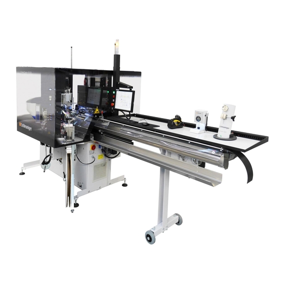
Page 36: Equipment Options
Swivel arm side 2 Touch Screen Conveyor belt Cable barrel (optional) Straightening unit Sealing station (optional) 10 Safety Cover 11 Crimping station (optional) 12 Operator 13 Deposit Gripper 36 | 190 Original Operating Manual | Edition 1.0 (03-2018) | CrimpCenter 36 SP... - Page 37 (V-Stripping blades) Cutting blades (top and bottom) Rejected part cutting blade (Rejected part cutting blade top and bottom - bottom not visible) Swivel arm side 2 37 | 190 Original Operating Manual | Edition 1.0 (03-2018) | CrimpCenter 36 SP...
- Page 38 Emergency stop button Conveyor belt Cable barrel (optional) Straightening unit (adjusting of wire / knot detection) Perforated disc Straightening roller Quick change guides Sealing station (optional) 38 | 190 Original Operating Manual | Edition 1.0 (03-2018) | CrimpCenter 36 SP...
-
Page 39: Processing Stations And Options
We continuously expand the assortment of available stations and options. Because of the modular design of the Schleuniger CrimpCenter 36 SP it is often possible to change the con- figuration of your CrimpCenter 36 SP later, to match your individual requirements. Ask your local Schleuniger sale &... -
Page 40: Available Processing Stations
CrimpCenter 36 SP if the correct processing stations and options are installed. The table below shows standard applications only. If you would like to perform other appli- cations on your CrimpCenter 36 SP, please do not hesitate to contact Schleuniger for a cus- tomized solution. -
Page 41: Available Quality Assurance
All options are available for all CrimpCenter models. Length encoder Standard Good / bad sorting Standard Horizontal and vertical wire Standard straightener 41 | 190 Original Operating Manual | Edition 1.0 (03-2018) | CrimpCenter 36 SP... - Page 42 The optional Guided Feasibili- ty Study shows the main char- acteristics of each application with regard to the monitoring capability and provides detailed information about demanding applications. 42 | 190 Original Operating Manual | Edition 1.0 (03-2018) | CrimpCenter 36 SP...
-
Page 43: Sample Configurations
CrimpCenter 36 SP. Sample Configuration 1 5.4.1 Fig. 6: Layout - Sample configuration 1 In this configurations the CrimpCenter 36 SP is equipped with two crimping stations (4, 5). Positioning Function Station Base machine Wire feed Base machine... -
Page 44: Sample Configuration 2
5. Product description Sample Configuration 2 5.4.2 Fig. 7: Layout - Sample configuration 1 In this configurations the CrimpCenter 36 SP is equipped with two crimping stations (4, 5). Positioning Function Station Base machine Wire feed Base machine Swivel arm side 1... -
Page 45: Sample Configuration 4
5. Product description In this configurations the CrimpCenter 36 SP is equipped with two crimping stations (4, 5). Positioning Function Station Base machine Wire feed Base machine Swivel arm side 1 Base machine Swivel arm side 2 Side 1, station 1... -
Page 46: Sample Configuration 5
5. Product description Sample Configuration 5 5.4.5 Fig. 10: Layout - Sample configuration 1 In this configurations the CrimpCenter 36 SP is equipped with two crimping stations (4, 5). Positioning Function Station Base machine Wire feed Base machine Swivel arm side 1... -
Page 47: Sample Configuration 6
5. Product description Sample Configuration 6 5.4.6 Fig. 11: Layout - Sample configuration 1 In this configurations the CrimpCenter 36 SP is equipped with two crimping stations (4, 5). Positioning Function Station Base machine Wire feed Base machine Swivel arm side 1... -
Page 48: Processing Stations And Options
5. Product description PROCESSING STATIONS AND OPTIONS The CrimpCenter 36 SP can be fit to the individual requirements of your production. A num- ber of stations and options allow a wide range of applications. Overview of available Stations 5.5.1 UniCrimp 221... - Page 49 All information are subject to change without prior notice and are only an overview. You might need additional devices mentioned in the remarks or modifications to your CrimpCenter 36 SP. 49 | 190 Original Operating Manual | Edition 1.0 (03-2018) | CrimpCenter 36 SP...
- Page 50 JAM-applicator All information is subject to change without prior notice. For modifications and supplements please contact your local Schleu- niger sales and service partner. 50 | 190 Original Operating Manual | Edition 1.0 (03-2018) | CrimpCenter 36 SP...
- Page 51 JAM-applicator All information is subject to change without prior notice. For modifications and supplements please contact your local Schleu- niger sales and service partner. 51 | 190 Original Operating Manual | Edition 1.0 (03-2018) | CrimpCenter 36 SP...
- Page 52 Refilling of seals during production All information is subject to change without prior notice. For modifications and supplements please contact your local Schleu- niger sales and service partner. 52 | 190 Original Operating Manual | Edition 1.0 (03-2018) | CrimpCenter 36 SP...
- Page 53 Setup gauge for AdapterKit SealCleaner 20 All information is subject to change without prior notice. For modifications and supplements please contact your local Schleu- niger sales and service partner. 53 | 190 Original Operating Manual | Edition 1.0 (03-2018) | CrimpCenter 36 SP...
- Page 54 All information is subject to change without prior notice. For modifications and supplements please contact your local Schleu- niger sales and service partner. 54 | 190 Original Operating Manual | Edition 1.0 (03-2018) | CrimpCenter 36 SP...
- Page 55 Options Separate support All information is subject to change without prior notice. For modifications and supplements please contact your local Schleu- niger sales and service partner. 55 | 190 Original Operating Manual | Edition 1.0 (03-2018) | CrimpCenter 36 SP...
- Page 56 All information is subject to change without prior notice. For modifications and supplements please contact your local Schleu- niger sales and service partner. 56 | 190 Original Operating Manual | Edition 1.0 (03-2018) | CrimpCenter 36 SP...
-
Page 57: Available Options
Faster change-over of crimp- Quick-change unit ing stations ToolingShuttle 30 (will be prepared outside of the CrimpCenter) Moving and store several Too- ShuttleRack for lingShuttle 30 ToolingShuttle 30 57 | 190 Original Operating Manual | Edition 1.0 (03-2018) | CrimpCenter 36 SP... -
Page 58: Depositing Table
The depositing table is designated for addi- tional devices, like PullTester or CHM. Overloading may lead to permanent dam- age of the depositing table. The maximum load must not exceed 15 58 | 190 Original Operating Manual | Edition 1.0 (03-2018) | CrimpCenter 36 SP... -
Page 59: Scope Of Delivery
Reject contact blade top Reject contact blade bottom V-stripping blade 0.5 (set, 4 pieces) V-stripping blade 0.1 (set, 4 pieces) V-stripping blade 1.5 (set, 4 pieces) 59 | 190 Original Operating Manual | Edition 1.0 (03-2018) | CrimpCenter 36 SP... -
Page 60: Blades
Other blade variations are available, to improve the results depending on the application if required. We are pleased to support you with our experience. Schleuniger GmbH Service Do not hesitate to contact the 60 | 190 Original Operating Manual | Edition 1.0 (03-2018) | CrimpCenter 36 SP... -
Page 61: Safety Elements / Danger Areas
Modifications not approved by Schleuniger GmbH voids the oper- ating license of the product. 61 | 190 Original Operating Manual | Edition 1.0 (03-2018) | CrimpCenter 36 SP... -
Page 62: Safety Cover - Pushbutton And Confirm Button
There must also be no contact between the safety cover and the connections of the stations. 62 | 190 Original Operating Manual | Edition 1.0 (03-2018) | CrimpCenter 36 SP... - Page 63 It is not possible to produce, when the safety cover is open. There are 3 confirm buttons to allow some rigging and setting-up operations. Position of the confirm buttons One confirm button is placed at the pneumatic unit beneath the straighten- ing unit 63 | 190 Original Operating Manual | Edition 1.0 (03-2018) | CrimpCenter 36 SP...
-
Page 64: Emergency Stop Switch
All values entered while programming, are held in memory as the power to the software sys- tem is not interrupted thereby. Position of the emergency stop switches Emergency Switch (1) Main circuit breaker (2) 64 | 190 Original Operating Manual | Edition 1.0 (03-2018) | CrimpCenter 36 SP... -
Page 65: Safety Cover Switch
Safety cover switch on the CrimpCenter This safety switch (1) is coupled with the safety cover (2) . It is not possible to produce, when the safety cove is open. 65 | 190 Original Operating Manual | Edition 1.0 (03-2018) | CrimpCenter 36 SP... -
Page 66: Danger Zones Generally
Improper handling can lead to injury or death. DANGER Risk of injury without personal protective equipment! The following instructions are to be followed! Observe the use of the personal protective equipment. 66 | 190 Original Operating Manual | Edition 1.0 (03-2018) | CrimpCenter 36 SP... -
Page 67: Danger Zones When Safety Cover Is Closed
Even if the machine is switched off the assemblies are energized! Danger of electric shock! In the area of the cable tray Machine starts automatically! Danger of hand injury! There is a risk of crushing! 67 | 190 Original Operating Manual | Edition 1.0 (03-2018) | CrimpCenter 36 SP... -
Page 68: Danger Zones When Safety Cover Is Open
There is a risk of injury by moving parts! Danger zones when Safety Cover is open 6.4.2 Topview when safety cover is open Fig. 13: Top view - Safety cover opened 68 | 190 Original Operating Manual | Edition 1.0 (03-2018) | CrimpCenter 36 SP... - Page 69 Area in the machine base frame The machine is equipped with a independent power supply. Even if the machine is switched off the assemblies are energized! Danger of electric shock! 69 | 190 Original Operating Manual | Edition 1.0 (03-2018) | CrimpCenter 36 SP...
-
Page 70: Installation / Mounting
Be sure to observe the maintenance leaflet for surface care (in the manual of the base machine). Damage to the surface coating must be repaired immediately. 70 | 190 Original Operating Manual | Edition 1.0 (03-2018) | CrimpCenter 36 SP... - Page 71 Remove wrapping and transportation locks, if any, not before the final place of installation is reached. Install the CrimpCenter 36 SP in a horizontal and stress-free posi- tion using the installation devices. Height from floor to the upper side of the aluminum base plate must be 31.6" (790 mm). The height adjustable hinged feet must be secured by tightening the counter nuts.
-
Page 72: Positioning / (Dis-) Mounting
The monitor is calibrated for each individual CrimpCenter 36 SP. The frame number of the CrimpCenter 36 SP can be found on the pack- aging of the monitor. For operating the CrimpCenter 36 SP the touch screen must be instal- led at its final position. -
Page 73: Removing The Conveyor Belt
Mounting of the guide rods 7.2.3 The guide rods of the safety cover of the CrimpCenter 36 SP are unmounted for transporta- tion. It is essential to install these guide rods before the safety cover is opened for the first time! The guide rods are part of the accessories of the machine delivery. -
Page 74: Electric Installation
The paper winder is fixed with 2 screws on the underside of the platform. 2.▹ Remove the screws and take away the paper winder. 74 | 190 Original Operating Manual | Edition 1.0 (03-2018) | CrimpCenter 36 SP... - Page 75 DANGER Risk of injury due to electrical voltage! The following instructions are to be followed! Training of staff shall be in compliance with government regula- tions. 75 | 190 Original Operating Manual | Edition 1.0 (03-2018) | CrimpCenter 36 SP...
- Page 76 Supplies The electric and pneumatic support will be routed through the operator column. A factory ground connection can be con- nected to the marked screw. 76 | 190 Original Operating Manual | Edition 1.0 (03-2018) | CrimpCenter 36 SP...
-
Page 77: Processing Stations
PROCESSING STATIONS The CrimpCenter will be shipped with the processing stations ordered. Usually their position will not be changed. The stations should only be mounted or dismounted by trained Schleuniger specialist. Thereby observe the following points: ATTENTION: After changing the position of a station, check if the safety cover is still safe. The complete area inside the safety cover has to be protected. -
Page 78: Commissioning
The person, which is actuating the confirm button, is responsible that no other person is in the danger zones! Only trained personnel are allowed to use the confirm button. 78 | 190 Original Operating Manual | Edition 1.0 (03-2018) | CrimpCenter 36 SP... -
Page 79: Starting Conditions
Damage to the surface coating must be repaired immediately. STARTING CONDITIONS The following conditions must be fulfilled to start the CrimpCenter 36 SP machine. The machine has to be properly mounted and connected to the power supply and the pneumatic support. - Page 80 Emergency stop switch not activated Condition of the emergency stop switches Emergency stop activated Overview pneumatic Pneumatic unit (beneath the straightening unit) Symbols - overview Shut off valve 80 | 190 Original Operating Manual | Edition 1.0 (03-2018) | CrimpCenter 36 SP...
-
Page 81: Protective Guard Plates
Such openings have to be closed immediately by the according cover plates. The cover plates may be mounted only with the included mounting parts by qualified personnel! 81 | 190 Original Operating Manual | Edition 1.0 (03-2018) | CrimpCenter 36 SP... - Page 82 Protective Guard Plate S2 55 degr. CC36S Protective Guard Plate S2 55 degr. w/o BF CC36S 457 740 Protective Guard Plate S1 55 degr. w/o BF CC36S 82 | 190 Original Operating Manual | Edition 1.0 (03-2018) | CrimpCenter 36 SP...
- Page 83 The picture beside shows the mounted plate if no ToolingShuttle holder is present at the position. It will be mounted with the existing screw and the washer. 83 | 190 Original Operating Manual | Edition 1.0 (03-2018) | CrimpCenter 36 SP...
- Page 84 It will be fixed with two M6 x 10 cylinder head screws and two 6.4 washers. Position 3: Article number 458 802; "Protective guard plate S1 55 degr. CC36S” 84 | 190 Original Operating Manual | Edition 1.0 (03-2018) | CrimpCenter 36 SP...
- Page 85 Please see next picture too. The M6 x 30 cylinder head screw will be secured with an M6 nut and a 6.4 washer at the underside. 85 | 190 Original Operating Manual | Edition 1.0 (03-2018) | CrimpCenter 36 SP...
- Page 86 M8 x 12 cylinder head screw and the 8.4 washer. Position 5: Article number 458 791; "Protective guard plate S2 55 degr. CC36S” 86 | 190 Original Operating Manual | Edition 1.0 (03-2018) | CrimpCenter 36 SP...
- Page 87 M6 x 10 cylinder head screw and a 6.4 washer. Under certain circumstances the spool hold- er has to be moved slightly. 87 | 190 Original Operating Manual | Edition 1.0 (03-2018) | CrimpCenter 36 SP...
-
Page 88: Mounting The Toolingshuttle
Following the log-in you can setup and configure according to your needs. For further information about the operat- ing with the EASY software please see the EASY operating manual. 88 | 190 Original Operating Manual | Edition 1.0 (03-2018) | CrimpCenter 36 SP... -
Page 89: Open The Safety Cover
CONFIRM BUTTONS Position of the confirm buttons One confirm button is placed at the pneumatic unit beneath the straighten- ing unit 89 | 190 Original Operating Manual | Edition 1.0 (03-2018) | CrimpCenter 36 SP... -
Page 90: Adjust The Working Height Of The Unicrimp 221/222
With the lever in the left position (see picture) using the wrench will move the station down. With the lever in the right position the station will be moved up. 90 | 190 Original Operating Manual | Edition 1.0 (03-2018) | CrimpCenter 36 SP... -
Page 91: Mount The Guide Tubes
The wire should slide easily through all parts of the wire guide, without having too much clearance. The diameter of the front guide tube has to be entered in the EASY menu Set/Line/Wire. Operating unit 1.▹ Switch off the control voltage! 91 | 190 Original Operating Manual | Edition 1.0 (03-2018) | CrimpCenter 36 SP... - Page 92 4.▹ The lever has to face towards the cutting unit. 5.▹ Put the guide tube onto the tube holder. The pin on the bottom will fit into the boring of the holder. 92 | 190 Original Operating Manual | Edition 1.0 (03-2018) | CrimpCenter 36 SP...
-
Page 93: Insert Wire
Operating unit 1.▹ Switch off the control voltage! 93 | 190 Original Operating Manual | Edition 1.0 (03-2018) | CrimpCenter 36 SP... - Page 94 7.▹ By turning the knob (3), the lower row of rollers can be adjusted. (Picture: Straightener for thin wires) 8.▹ Open the horizontal straightening device with the quick-lock. 94 | 190 Original Operating Manual | Edition 1.0 (03-2018) | CrimpCenter 36 SP...
- Page 95 The wire must be slightly deformed by the rollers (see picture). 12.▹If necessary correct the distance of the rollers with the fine adjustment. (Picture: Straightener for standard wires) 95 | 190 Original Operating Manual | Edition 1.0 (03-2018) | CrimpCenter 36 SP...
- Page 96 The first part of the wire should be as straight as possible and there must not be any curves. If necessary straighten the wire manually. 15.▹Lead the wire through the first wire guide. 96 | 190 Original Operating Manual | Edition 1.0 (03-2018) | CrimpCenter 36 SP...
- Page 97 Wire feeding unit 20.▹Close the feeding belts of the wire feed- ing unit. Therefore use the trigger switch. 97 | 190 Original Operating Manual | Edition 1.0 (03-2018) | CrimpCenter 36 SP...
-
Page 98: Adjust The Contact Pressure Of The Wire Feed
The default setting is 5 bars. Manual version The pressure regulator is located at the pneumatic unit under wire straightening unit. 1.▹ Set the desired contact pressure here. 98 | 190 Original Operating Manual | Edition 1.0 (03-2018) | CrimpCenter 36 SP... -
Page 99: Adjust The Clamping Force Of The Gripper
99 | 190 Original Operating Manual | Edition 1.0 (03-2018) | CrimpCenter 36 SP... - Page 100 The set pressure is saved with the order data. The pressure is automatically adjusted on load of the order. The pressure of the active order will be applied. 100 | 190 Original Operating Manual | Edition 1.0 (03-2018) | CrimpCenter 36 SP...
-
Page 101: Conveyor Belt
In the area of the tilting tray there is a risk of crushing WARNING Risk of injury due to independent starting! The cable tray moves out independently! 101 | 190 Original Operating Manual | Edition 1.0 (03-2018) | CrimpCenter 36 SP... - Page 102 The cable tray moves the processed wires into removal position. Continuous Quality Control In the sampling area, individual wires can be removed during production to carry out con- tinuous quality control. 102 | 190 Original Operating Manual | Edition 1.0 (03-2018) | CrimpCenter 36 SP...
-
Page 103: Referencing
Because the safety cover is open for referencing the confirm button has to be pushed for some actions when the machine executes movements. The confirmation button must also be pressed to confirm some messages in EASY. 103 | 190 Original Operating Manual | Edition 1.0 (03-2018) | CrimpCenter 36 SP... - Page 104 EASY-Software (1 / 26) "Please switch on the control voltage. The gripper side 2 closes." CrimpCenter 5.▹ Switch on the control voltage. The gripper side 2 will automatically close. 104 | 190 Original Operating Manual | Edition 1.0 (03-2018) | CrimpCenter 36 SP...
- Page 105 "Remove the upper cutter block." CrimpCenter 11.▹Remove the highlighted knurled screw at the upper cutter block. Caution! Secure the cutter block from falling down! Note the next step. 105 | 190 Original Operating Manual | Edition 1.0 (03-2018) | CrimpCenter 36 SP...
- Page 106 "Place the setup gauge in the upper section and fix it with the screw." CrimpCenter 16.▹Place the setup gauge in the upper cut- ting unit holder. 17.▹Fix these with the knurled screw. 106 | 190 Original Operating Manual | Edition 1.0 (03-2018) | CrimpCenter 36 SP...
- Page 107 Do not use long guide tubes." CrimpCenter 21.▹Move the swivel arm side 1 to the setup gauge as pictured. Do not use long guide tubes. There is a risk of collision. 107 | 190 Original Operating Manual | Edition 1.0 (03-2018) | CrimpCenter 36 SP...
- Page 108 2 by hand. 26.▹Position the swivel above the setup pin. Notice: The gripper may only grip the thin part of the setting gauge. 27.▹Close the gripper by hand. 108 | 190 Original Operating Manual | Edition 1.0 (03-2018) | CrimpCenter 36 SP...
- Page 109 32.▹In any case hold the confirm button as long as the machine moves. If the button will be released to early the referencing will be aborted and has to be restar- ted. 109 | 190 Original Operating Manual | Edition 1.0 (03-2018) | CrimpCenter 36 SP...
- Page 110 "Unscrew the upper screw and remove the setup gauge and put it to the accessories." CrimpCenter 37.▹Remove the knurled screw. 38.▹Remove the setup gauge. Caution! Secure the cutter block from falling down! 110 | 190 Original Operating Manual | Edition 1.0 (03-2018) | CrimpCenter 36 SP...
- Page 111 EASY-Software (25 / 26) "Mount the upper cutter block." CrimpCenter 42.▹Mount the upper cutter block. 43.▹Fix it with the marked knurled screw. 111 | 190 Original Operating Manual | Edition 1.0 (03-2018) | CrimpCenter 36 SP...
-
Page 112: Deposit Gripper
(Article number 50000 581 898) EASY-Software (4/18)) show The bolt marked headings (e.g. where an information is shown and / or where an action has to be carried out. 112 | 190 Original Operating Manual | Edition 1.0 (03-2018) | CrimpCenter 36 SP... - Page 113 "Initialization of the setup assistant for the deposit gripper. ” CrimpCenter 4.▹ Confirm the message. EASY-Software (3 / 20) “Please open the safety cover. ” CrimpCenter 5.▹ Open the safety cover. 113 | 190 Original Operating Manual | Edition 1.0 (03-2018) | CrimpCenter 36 SP...
- Page 114 ” CrimpCenter 12.▹Swivel the setup pin under the deposit gripper so that only the thin area of the setup pin is gripped. 114 | 190 Original Operating Manual | Edition 1.0 (03-2018) | CrimpCenter 36 SP...
- Page 115 "Switch-off the compressed air by closing the blocking valve of the gripper side 1." CrimpCenter 17.▹Close the blocking valve of the gripper side 2. (Picture: Valve position = closed) 115 | 190 Original Operating Manual | Edition 1.0 (03-2018) | CrimpCenter 36 SP...
- Page 116 EASY-Software (3 / 20) “Please close the safety cover. ” CrimpCenter 23.▹Lower the safety cover. EASY Software "Referencing completed." CrimpCenter 24.▹Confirm message. The referencing is completed. ➥ 116 | 190 Original Operating Manual | Edition 1.0 (03-2018) | CrimpCenter 36 SP...
-
Page 117: Crimp Station
1.▹ The crimping station or twisting station must be loaded. See EASY-Software manual. CrimpCenter 1.▹ Open the safety cover. 117 | 190 Original Operating Manual | Edition 1.0 (03-2018) | CrimpCenter 36 SP... - Page 118 CrimpCenter 6.▹ Switch off the air pressure supply on the main valve. 7.▹ Set the centering pin as far as it goes in the outlet guide. 118 | 190 Original Operating Manual | Edition 1.0 (03-2018) | CrimpCenter 36 SP...
- Page 119 12.▹Move the centering pin with the arrow buttons (1) exactly to the middle of the setup gauge. 119 | 190 Original Operating Manual | Edition 1.0 (03-2018) | CrimpCenter 36 SP...
- Page 120 (Article number 50000 586 799) Setup gauge, UniCrimp 220 (Article number 50000 133 489) The bolt marked headings (e.g. EASY-Software (4/18)) show where an information is shown 120 | 190 Original Operating Manual | Edition 1.0 (03-2018) | CrimpCenter 36 SP...
- Page 121 EASY software. EASY Software 4.▹ Push the pictured Machine menu but- tons in sequence. "Please remove the wire." CrimpCenter 5.▹ Make sure that the wire is removed. 121 | 190 Original Operating Manual | Edition 1.0 (03-2018) | CrimpCenter 36 SP...
- Page 122 Be careful not to collide with any pro- cessing station. The centering pin should be in the middle of the referencing tool. EASY Software 10.▹Confirm the message. 122 | 190 Original Operating Manual | Edition 1.0 (03-2018) | CrimpCenter 36 SP...
-
Page 123: Towerlight
The referencing is completed. ➥ TOWERLIGHT 8.14 The Towerlight displays the status of the CrimpCenter with a colored light and is available in two different versions 123 | 190 Original Operating Manual | Edition 1.0 (03-2018) | CrimpCenter 36 SP... - Page 124 "SERVICE". When this switch is activated, the blue signal element lights up. It is immediately apparent that the CrimpCenter is in the maintenance mode. Inactive Active 124 | 190 Original Operating Manual | Edition 1.0 (03-2018) | CrimpCenter 36 SP...
-
Page 125: Servicing / Maintenance
Maintenance interval The maintenance sheets (base machine) comprise information on how to perform mainte- nance and repair. Keep the CrimpCenter 36 SP in an operational and safe condition when executing these activities. Observe the safety instructions given in the maintenance sheets. The maintenance sheets appear in the same order as listed in the maintenance table. -
Page 126: Safety Instructions
Always follow the maintenance and safety instructions of the man- ufacturer´s documentation when doing maintenance or repair work on processing stations or options. 126 | 190 Original Operating Manual | Edition 1.0 (03-2018) | CrimpCenter 36 SP... -
Page 127: Personnel Qualification
The following instructions are to be followed! This ensures that the product is repaired properly. Personal protective equipment 9.2.3 See chapter "2.11 Personal protective equipment (Page 23)". 127 | 190 Original Operating Manual | Edition 1.0 (03-2018) | CrimpCenter 36 SP... -
Page 128: Customer Service
Trouble Shooting Procedure 9.3.2 If problems occur, which cannot be solved by the help of this manual, the Schleuniger dis- tributor or the technical staff of Schleuniger is ready to assist you. In such situations it is essential to provide a precise description of the matter:... - Page 129 1 min. Monthly Qualified Personnel Check and exchange filter ele- (174) approx. 10 Weekly Qualified Personnel ments min. Check conveyor belt (177) approx. 5 min. Weekly Qualified Personnel 129 | 190 Original Operating Manual | Edition 1.0 (03-2018) | CrimpCenter 36 SP...
-
Page 130: Maintenance Sheet - Check Safety Devices
The operating company has to make sure that the safety devices are checked yearly accord- ing to the following instruction. The checks must be recorded. It is recommend taking the checks into the operator instruction. If one of the tests is negative, stop the machine! Immediately contact the Schleuniger service. WARNING... -
Page 131: Emergency Stop Switch
The operating company has to make sure that the safety devices are checked yearly accord- ing to the following instruction. The checks must be recorded. It is recommend taking the checks into the operator instruction. 131 | 190 Original Operating Manual | Edition 1.0 (03-2018) | CrimpCenter 36 SP... - Page 132 9. Servicing / Maintenance If one of the tests is negative, stop the machine! Immediately contact the Schleuniger service. WARNING Personnel Qualification and Personal Protective Equipment! The following instructions are to be followed! The test and report may only be executed by technical specialists.
- Page 133 7.▹ Release the emergency stop button. The machine must not start automatical- 8.▹ Repeat the test with all emergency stop buttons. Pictures may differ from your product. 133 | 190 Original Operating Manual | Edition 1.0 (03-2018) | CrimpCenter 36 SP...
-
Page 134: Confirm Buttons
The operating company has to make sure that the safety devices are checked yearly accord- ing to the following instruction. The checks must be recorded. It is recommend taking the checks into the operator instruction. If one of the tests is negative, stop the machine! Immediately contact the Schleuniger service. WARNING... -
Page 135: Safety Cover Pushbutton
Task Check the pneumatic valves of the safety cover. Unit Entire machine - Safety cover, operating column. pneumatic unit Duration Interval Personnel qualifica- Qualified Personnel tion 135 | 190 Original Operating Manual | Edition 1.0 (03-2018) | CrimpCenter 36 SP... - Page 136 The operating company has to make sure that the safety devices are checked yearly accord- ing to the following instruction. The checks must be recorded. It is recommend taking the checks into the operator instruction. If one of the tests is negative, stop the machine! Immediately contact the Schleuniger service. WARNING...
-
Page 137: Safety Cover Switch
The operating company has to make sure that the safety devices are checked yearly accord- ing to the following instruction. The checks must be recorded. It is recommend taking the checks into the operator instruction. If one of the tests is negative, stop the machine! Immediately contact the Schleuniger service. WARNING... - Page 138 This means that e.g. in the "Sample" menu the confirm button has to be pushed to execute actions with the machine. 138 | 190 Original Operating Manual | Edition 1.0 (03-2018) | CrimpCenter 36 SP...
-
Page 139: Safety Cover
The operating company has to make sure that the safety devices are checked yearly accord- ing to the following instruction. The checks must be recorded. It is recommend taking the checks into the operator instruction. If one of the tests is negative, stop the machine! Immediately contact the Schleuniger service. WARNING... -
Page 140: Safety Cover
The operating company has to make sure that the safety devices are checked yearly accord- ing to the following instruction. The checks must be recorded. It is recommend taking the checks into the operator instruction. If one of the tests is negative, stop the machine! Immediately contact the Schleuniger service. 140 | 190... -
Page 141: Motors
The operating company has to make sure that the safety devices are checked yearly accord- ing to the following instruction. The checks must be recorded. It is recommend taking the checks into the operator instruction. If one of the tests is negative, stop the machine! Immediately contact the Schleuniger service. 141 | 190... - Page 142 3.▹ Bring the machine into initial position. To do so one of the confirm buttons has to be pressed. 4.▹ After the machine has stopped the movement release the confirm button. 142 | 190 Original Operating Manual | Edition 1.0 (03-2018) | CrimpCenter 36 SP...
- Page 143 7.▹ Now the swivel arm can be moved easi- 8.▹ Confirm the error message. 9.▹ Go to menu "Sample" or "Production". 10.▹Bring the machine with the highlighted button back in initial position. 143 | 190 Original Operating Manual | Edition 1.0 (03-2018) | CrimpCenter 36 SP...
- Page 144 13.▹Move the belt of the wire feed. Pictures may differ from your product. 14.▹Move the swivel S2. 15.▹Move the stripping unit S2. (Picture: CrimpCenter 36 SP) 144 | 190 Original Operating Manual | Edition 1.0 (03-2018) | CrimpCenter 36 SP...
-
Page 145: Pneumatic
The operating company has to make sure that the safety devices are checked yearly accord- ing to the following instruction. The checks must be recorded. It is recommend taking the checks into the operator instruction. If one of the tests is negative, stop the machine! Immediately contact the Schleuniger service. WARNING... -
Page 146: Conveyor Belt
The operating company has to make sure that the safety devices are checked yearly accord- ing to the following instruction. The checks must be recorded. It is recommend taking the checks into the operator instruction. If one of the tests is negative, stop the machine! Immediately contact the Schleuniger service. WARNING... -
Page 147: Power Sockets
The operating company has to make sure that the safety devices are checked yearly accord- ing to the following instruction. The checks must be recorded. It is recommend taking the checks into the operator instruction. If one of the tests is negative, stop the machine! Immediately contact the Schleuniger service. 147 | 190... - Page 148 As an example the picture shows a power socket on the side of the base frame. (Picture: CrimpCenter 36 SP) 148 | 190 Original Operating Manual | Edition 1.0 (03-2018) | CrimpCenter 36 SP...
-
Page 149: Maintenance Sheet - Check Machine
The operating company has to make sure that the safety devices are checked yearly accord- ing to the following instruction. The checks must be recorded. It is recommend taking the checks into the operator instruction. If one of the tests is negative, stop the machine! Immediately contact the Schleuniger service. WARNING... -
Page 150: Maintenance Sheet - Surface Cleaning And Prevention
Protect the machine against reactivation. Take appropriate measures to ensure, that only you can reactivate the machine. Affix a warning sign: "Do not switch on the Machine!" 150 | 190 Original Operating Manual | Edition 1.0 (03-2018) | CrimpCenter 36 SP... -
Page 151: Touch Screen
The following instructions are to be followed! Maintenance work may only be executed by technical specialist. See also chapter “Personnel Qualification” and “Personal Protective Equipment”. Material 151 | 190 Original Operating Manual | Edition 1.0 (03-2018) | CrimpCenter 36 SP... -
Page 152: Pet - Surfaces
Microfiber clothes (minimum metal parts) Glass cleaner Task 1.▹ Wet the cloth with the cleaner generously and clean the surface, 2.▹ Dry the surface with a dry cloth. 152 | 190 Original Operating Manual | Edition 1.0 (03-2018) | CrimpCenter 36 SP... -
Page 153: Plastic / Rubber / Eladur
The following instructions are to be followed! Maintenance work may only be executed by technical specialist. See also chapter “Personnel Qualification” and “Personal Protective Equipment”. Task No cleaning! 1.▹ 153 | 190 Original Operating Manual | Edition 1.0 (03-2018) | CrimpCenter 36 SP... -
Page 154: Steel Surfaces - Stainless Steel (V2A)
Maintenance work may only be executed by technical specialist. See also chapter “Personnel Qualification” and “Personal Protective Equipment”. Material Lint-free cloth WD40 spray oil Task 1.▹ Rub the surface with an oiled cloth. 154 | 190 Original Operating Manual | Edition 1.0 (03-2018) | CrimpCenter 36 SP... -
Page 155: Steel Surfaces - Crude Steel (Guide Rails)
3.▹ Make sure that no lubricant is applied to other areas, such as belts or electric parts. 4.▹ Remove excessive or dripping lubricant with an absorbent cloth. 155 | 190 Original Operating Manual | Edition 1.0 (03-2018) | CrimpCenter 36 SP... -
Page 156: Steel Surfaces - Nitrified Steel
Maintenance work may only be executed by technical specialist. See also chapter “Personnel Qualification” and “Personal Protective Equipment”. Material Lint-free cloth WD40 spray oil Task 1.▹ Rub the surface with an oiled cloth. 156 | 190 Original Operating Manual | Edition 1.0 (03-2018) | CrimpCenter 36 SP... -
Page 157: Zinc Coated Surfaces
The following instructions are to be followed! Maintenance work may only be executed by technical specialist. See also chapter “Personnel Qualification” and “Personal Protective Equipment”. Material 157 | 190 Original Operating Manual | Edition 1.0 (03-2018) | CrimpCenter 36 SP... -
Page 158: Aluminum Surfaces
Lint-free cloth Glass cleaner WD40 spray oil Task 1.▹ Wet cloth with a glass cleaner and clean surface. 2.▹ Rub the surface with an oiled cloth. 158 | 190 Original Operating Manual | Edition 1.0 (03-2018) | CrimpCenter 36 SP... -
Page 159: Powdered / Painted Surfaces
2.▹ Remove damages of the surface like scratches with the paint stick if necessary. 3.▹ Wait until the paint is dry. 4.▹ Rub the surface with an oiled cloth. 159 | 190 Original Operating Manual | Edition 1.0 (03-2018) | CrimpCenter 36 SP... -
Page 160: Tinning Station / Surrounding Parts
1.▹ Clean the outside of the flux tank, the tinning station and surrounding parts in conformi- ty with the Flux manufacturer´s instructions. 2.▹ Clean the metal surfaces with an oil saturated cloth. 3.▹ Clean other surfaces with an oil saturated cloth. 160 | 190 Original Operating Manual | Edition 1.0 (03-2018) | CrimpCenter 36 SP... -
Page 161: Maintenance Sheet - Lubricate Guide Rail(S)
Take appropriate measures to ensure, that only you can reactivate the machine. Affix a warning sign: "Do not switch on the Machine!" 1.▹ Use the grease gun at the highlighted grease fittings. 161 | 190 Original Operating Manual | Edition 1.0 (03-2018) | CrimpCenter 36 SP... -
Page 162: Maintenance Sheet - Cleaning The Cutter Blocks
Remove carrier strip splits, wire or insulation leftovers with a vac- uum cleaner and do not blow them off with compressed air. Do not use any sharp-edged objects when cleaning the machine. 162 | 190 Original Operating Manual | Edition 1.0 (03-2018) | CrimpCenter 36 SP... - Page 163 1.▹ Check the cutter blocks and the sur- rounding parts for impurities and wire and insulation leavings. 2.▹ Remove them with a soft brush or vac- uum them. 163 | 190 Original Operating Manual | Edition 1.0 (03-2018) | CrimpCenter 36 SP...
-
Page 164: Maintenance Sheet - Exchanging Blade
The following instructions are to be followed! For works on the blades and the cutter blocks wear cut resistant gloves, when the safety cover is open! 164 | 190 Original Operating Manual | Edition 1.0 (03-2018) | CrimpCenter 36 SP... - Page 165 3.▹ Remove the highlighted knurled screw at the bottom cutter block. 4.▹ After removing the screw the cutter block can be taken out. 165 | 190 Original Operating Manual | Edition 1.0 (03-2018) | CrimpCenter 36 SP...
- Page 166 Stacking arrangement The schematic view shows the mounting direction and the order of the cutting and Wire feed stripping blades (in the picture painted in yellow). 166 | 190 Original Operating Manual | Edition 1.0 (03-2018) | CrimpCenter 36 SP...
- Page 167 2.▹ To replace the blade turn out the screw, 3.▹ remove the existing blade 4.▹ and mount the new reject contact blade. 167 | 190 Original Operating Manual | Edition 1.0 (03-2018) | CrimpCenter 36 SP...
- Page 168 6.▹ remove the existing blade 7.▹ and mount the new reject contact blade. 8.▹ Push the conveyor belt towards the machine 9.▹ and secure it with the screw. 168 | 190 Original Operating Manual | Edition 1.0 (03-2018) | CrimpCenter 36 SP...
-
Page 169: Maintenance Sheet - Exchange Feeding Belts
Protect the machine against reactivation. Take appropriate measures to ensure, that only you can reactivate the machine. Affix a warning sign: "Do not switch on the Machine!" 169 | 190 Original Operating Manual | Edition 1.0 (03-2018) | CrimpCenter 36 SP... - Page 170 7.▹ and the flanged disks (2). Now the belts can be removed and replaced by new ones. 8.▹ Mount the flanged disks and the cylin- der head screws (2). 170 | 190 Original Operating Manual | Edition 1.0 (03-2018) | CrimpCenter 36 SP...
- Page 171 The required value is 210 Hz (+/- 10 Hz). 14.▹If necessary adjust the tension of the belts again. Both belts have to be checked. 171 | 190 Original Operating Manual | Edition 1.0 (03-2018) | CrimpCenter 36 SP...
-
Page 172: Maintenance Sheet - Dump Condensate
You may suffer serious injuries, if the machine is switched on acciden- tally! The pneumatic system is pressurized. Working on pressurized system can cause serious accidents. 172 | 190 Original Operating Manual | Edition 1.0 (03-2018) | CrimpCenter 36 SP... - Page 173 9. Servicing / Maintenance 1.▹ Check the collected condensate. 2.▹ Dump the water if necessary. Put an absorbent cloth under the drain valve and press the orange button. 173 | 190 Original Operating Manual | Edition 1.0 (03-2018) | CrimpCenter 36 SP...
-
Page 174: Maintenance Sheet - Filter Element(S)
Change interval of the filters! There are no fixed rules how often the filters have to be changed. The interval depends on the operating environment where the machine is operated. 174 | 190 Original Operating Manual | Edition 1.0 (03-2018) | CrimpCenter 36 SP... - Page 175 You will find the filter for the supply air beneath the operator panel. The two filters for the exhaust air are placed beneath the wire intake. 175 | 190 Original Operating Manual | Edition 1.0 (03-2018) | CrimpCenter 36 SP...
- Page 176 Now remove the grill. 3.▹ Remove the filter element 4.▹ and clean it. For reassembly, follow the steps in reversed order. 176 | 190 Original Operating Manual | Edition 1.0 (03-2018) | CrimpCenter 36 SP...
-
Page 177: Maintenance Sheet - Check Conveyor Belt
Take appropriate measures to ensure, that only you can reactivate the machine. Affix a warning sign: "Do not switch on the Machine!" 1.▹ Check the conveyor belt for damages and wearing. 177 | 190 Original Operating Manual | Edition 1.0 (03-2018) | CrimpCenter 36 SP... -
Page 178: Spare Parts
Risk of injury if operated by unqualified personnel! Disregarding may lead to injury. The following instructions are to be followed! For original Schleuniger spare parts see „Parts List“. 178 | 190 Original Operating Manual | Edition 1.0 (03-2018) | CrimpCenter 36 SP... -
Page 179: Decommissioning / Disposal
Observe the instructions for external component units provided in the manual of the manufacturer. Observe the separate manuals of the processing stations and options you are going to install, connect or disassemble. 179 | 190 Original Operating Manual | Edition 1.0 (03-2018) | CrimpCenter 36 SP... -
Page 180: Disassembly / Disposal
The battery in this product contains heavy metals which are harmful to the environment and is therefore hazardous waste. The following instructions are to be followed! Recycle the battery! 180 | 190 Original Operating Manual | Edition 1.0 (03-2018) | CrimpCenter 36 SP... -
Page 181: Overview Of Symbols
12. Overview of symbols OVERVIEW OF SYMBOLS The following table shows all stickers used on the CrimpCenter 36 SP. Depending on the equipment, some stickers may be not on the specific machine. Symbol Function Shut off valve The air supply for the complete machine will be switched on or off with the shut off valve. - Page 182 "6.1 Safety Cover - Pushbutton and Confirm Button (Page 62)". Feed wire The wire will be fed by pushing this button. See also chapter "8.9 Insert Wire (Page 93)". 182 | 190 Original Operating Manual | Edition 1.0 (03-2018) | CrimpCenter 36 SP...
- Page 183 Personnel older than 14 years Product name Fan exhaust Protective equipment Figure Foreseeable misuse Qualified personnel Ground connector Guidelines rating plate Recycle Registered trademarks Hotline Result 183 | 190 Original Operating Manual | Edition 1.0 (03-2018) | CrimpCenter 36 SP...
- Page 184 Time intervals Schleuniger distributor Schleuniger original fan filter Topic Screen titles Service technician Software version Weight Standards Warning notice Straightening unit Wire guide Symbols Wire type 184 | 190 Original Operating Manual | Edition 1.0 (03-2018) | CrimpCenter 36 SP...
-
Page 185: Personal Notes
................... . 185 | 190 Original Operating Manual | Edition 1.0 (03-2018) | CrimpCenter 36 SP... - Page 186 ................... . 186 | 190 Original Operating Manual | Edition 1.0 (03-2018) | CrimpCenter 36 SP...
-
Page 187: Additional Documents
14. Additional Documents ADDITIONAL DOCUMENTS 187 | 190 Original Operating Manual | Edition 1.0 (03-2018) | CrimpCenter 36 SP... -
Page 188: Wiring Diagrams
15. Wiring Diagrams WIRING DIAGRAMS 188 | 190 Original Operating Manual | Edition 1.0 (03-2018) | CrimpCenter 36 SP... - Page 191 Customer: Project: CC36SP_R17_473302 SUPPLY VOLTAGE CONTROL VOLTAGE Date: 20.02.18 Drawn by: G.Woitke...
- Page 192 Content of Page File Project page Comment Date CC36S_R2016_Plan.0001.wsELD Image 04.01.18 CC36S_R2016_Plan.0002.wsELD supply 400V 20.02.18 CC36S_R2016_Plan.0003.wsELD Connection variants Supply voltage 04.01.18 CC36S_R2016_Plan.0004.wsELD 400V AC distribution 04.01.18 CC36S_R2016_Plan.0005.wsELD USB disperse 04.01.18 CC36S_R2016_Plan.0006.wsELD Mains filter controller supply 04.01.18 CC36S_R2016_Plan.0007.wsELD 230V AC supply 04.01.18 CC36S_R2016_Plan.0008.wsELD conveyor belt...
- Page 193 Content of Page File Project page Comment Date CC36S_R2016_Plan.0036.wsELD Terminal setup 24V DC 12.01.18 CC36S_R2016_Plan.0037.wsELD Terminal setup 230/400V AC 04.01.18...
- Page 194 Date 20.02.18 Machine Type: Image Project number CC36 SP G.Woitke 458046 work Additional Information: check Drawing number sheet 473302 DIN 81346 created from Status rev. Date name norm...
- Page 195 Attention set to 3x400V Trafo 210V-500V -W-Q2 Ölflex-Control TM 5G2,5mm² 6000mm PE2a . L1' . L2' . L3' -W-Q4 Load Wire_horizontal network separate protective earth Line (PE) and neutral (N) system -W-Q1 /4.0 Ölflex-Control TM 5G2,5mm² 6000mm /4.0 PE1b /4.0 ÖLFLEX 110 CH 7G0,75 /4.0 gn-ye...
- Page 196 Connection possibilities of the transformer in the control cabinet primary Connect connection 1U4 - 1V5 210 V 1V4 - 1W5 1W4 - 1U5 1U3 - 1V5 230 V 1V3 - 1W5 1W3 - 1U5 1U1 - 1V5 250 V 1V1 - 1W5 1W1 - 1U5 1U4 - 1V6 380 V...
- Page 197 black /2.8 black /2.8 black /2.8 light blue /2.8 /7.0 green-yellow /2.8 /6.0 -F02 -F03 C10A C16A option STS 1100 1,5mm² 1,5mm² 1,5mm² 2,5mm² . gr . gr . gr . gr . gr . gr 24V DC= . hbl .
- Page 198 supply USB Hub USB-HUB /4.6 extension of USB connections about HUB standard usb connections -X20 Computer USB power point BarcodeScanner Touch Monitor SW patch necessary (Option) -X23 USB power point standard cabinet Operator side reserve remote control (option) -X30 reserve USB power point Labelprinter SW patch necessary...
- Page 199 black black black green-yellow PE /7.0 /4.8 2,5mm² -F01 . L1 . L2 . L3 Load Filter 3pin Line L7' /9.0 L8' /9.0 L9' /9.0 Date 20.02.18 Machine Type: Mains filter controller supply Project number CC36 SP G.Woitke 458046 work Additional Information: check Drawing number...
- Page 200 black /4.1 /8.0 black /4.1 /8.0 black /4.1 /8.0 light blue /4.8 /8.0 green-yellow /6.7 /8.0 2,5mm² -F04 -F05 -F06 -F07 C 16A C 16A C 16A C 16A light blue 1,5mm² 2,5mm² 230V AC 230V AC 230V AC 230V AC .
- Page 201 black /7.8 black /7.8 black /7.8 light blue /7.8 -K3.1 -K3.1 -K3.1 -K3.5 green-yellow /7.8 /9.0 Digital output Digital output Digital output Digital output 2,5mm² Feeding release Conveyor belt speedbit0 Conveyor belt speedbit1 Conveyor belt speedbit2 -F08 /33.0 /33.0 /33.0 /34.0 -WXM20 Ölflex 5G 1,5mm²...
- Page 202 L7' /10.0 /6.7 L8' /10.0 /6.7 L9' /10.0 /6.7 PE /10.0 /8.2 -T11-13 24V DC /11.0 Powerlink Powerlink /10.0 /32.8 Trigger Trigger /10.0 /21.7 Quickstop/Prefeeder /25.7 -X300 powerlink Display Ground connection on mounting plate -T10 /CE:1.5 -B11-1 -B11-1 -M11 -M13 wire feeder + haul off side 1 swivel arm side 1 Date...
- Page 203 /9.8 /9.8 /9.8 /9.8 -T15-16 24V DC /11.0 Powerlink /9.8 Trigger /9.8 QuickstopA QuickstopB /25.7 /25.6 -X300 powerlink Display Ground connection on mounting plate -T11 /CE:1.6 -B11-1 -B11-1 -B11-1 -M12 -M15 -M16 cutting head swivel arm side 2 pull-of unit side 2 Date 20.02.18 Machine Type:...
- Page 204 clamp T6,3A T6,3A T6,3A -X301 side 1 side 2 station 1, 2, 3 station 1, 2, 3 Date 20.02.18 Machine Type: 24V DC allocation Project number CC36 SP G.Woitke 458046 work Additional Information: check Drawing number sheet 473302 DIN 81346 created from Status rev.
- Page 205 X300 0V DC X300 0V DC /4.2 /19.0 -X300 -X301 -W22.2 -W22.5 Ölflex 3x1 Ölflex 3x1 -W22.1 -W22.3 -W22.4 -W22.6 Ölflex 3x1 Ölflex 3x1 Ölflex 3x1 Ölflex 3x1 -X2.1 -X2.2 -X2.5 -X2.1.2 -X2.2.2 -X2.3.2 24VDC 24VDC 24VDC 24VDC 24VDC 24VDC 24VDC station 1 station 2...
- Page 206 -K3.S1 -K3.S1 Digital output Digital output Pulse output 1 safety Pulse output 2 safety Puls 1 Puls 2 option /33.2 /33.2 bridge of X16 1->2 and 3->4 Puls1 Puls2 /21.0 /21.0 option -W15.2 Ölflex 7G0,75mm² emergency stop button -S01 -W15.2 option Ölflex 7G0,75mm²...
- Page 207 -K3.S2 Safety output 2pin release main relay /33.4 -X301 -X301 -W15.1 ÖLFLEX 15G0,75 -S02 -S03 -W15.1 ÖLFLEX 15G0,75 15kW /33.2 /33.2 /33.2 main relay feedback main relay OFF-Button ON-Button Digital input Digital input Digital input -K3.2 -K3.2 -K3.2 /4.1 /4.1 /4.1 /4.1 /4.1...
- Page 208 -K3.3 -K3.3 Digital output Digital output side 1 station 1 P1 side 1 station 1 P3 station connection -XST1.1 /33.4 /33.4 -K3.3 -K3.3 Digital output Digital output side 1 station 1 P2 side 1 station 1 P4 free cable end insulate /33.4 /33.4...
- Page 209 -K3.3 -K3.3 Digital output Digital output side 1 station 2 P1 side 1 station 2 P3 station connection -XST1.2 /33.4 /33.4 -K3.3 -K3.3 Digital output Digital output side 1 station 2 P2 side 1 station 2 P4 free cable end insulate /33.4 /33.4...
- Page 210 -K3.3 -K3.3 Digital output Digital output station connection side 2 station 1 P1 side 2 station 1 P3 -XST2.1 /33.4 /33.4 -K3.3 -K3.3 free cable end Digital output Digital output insulate side 2 station 1 P2 side 2 station 1 P4 /33.4 /33.4 /33.6...
- Page 211 -K3.3 -K3.3 Digital output Digital output side 2 station 2 P1 side 2 station 2 P3 station connection -XST2.2 /33.4 /33.4 -K3.3 -K3.3 Digital output Digital output side 2 station 2 P2 side 2 station 2 P4 free cable end insulate /33.4 /33.4...
- Page 212 X301-P 24V DC X301-P 24V DC /11.2 /22.0 X300 0V DC X300 0V DC /12.8 /22.0 -Q2.13 X501-G 24V DC X501-G 24V DC /11.2 /22.0 -X301 -X300 -X501 main relay on -XSR31 /14.5 -X301 -X501 -X300 -X88 -W23.1 -W15.1 ÖLFLEX CLASSIC 100 2X0,5 ÖLFLEX 15G0,75 1550mm -SR31...
- Page 213 -K3.S1 -K3.S1 -K3.1 Digital output Digital output Digital output Pulse output 3 safety Pulse output 4 safety Signal lamp conf.button /33.2 /33.2 /33.0 -W15.1 -W17.1 ÖLFLEX CLASSIC 100 15G0,75 Ölflex 6*0,75mm² confirm push button 1 confirm push button 2 confirm push button 3 tie bar straightening unit straightening unit...
- Page 214 -K3.S2 -K3.S2 Puls2 Puls 2 /19.4 Safety output Safety output /13.2 enable Q14 enable Q15 Puls1 Puls1 /23.6 /13.0 /33.4 /33.4 0V DC 24V DC -X301 -X300 -Q14 -W24.2 /CE:1.4 ÖLFLEX 5G0,75 -Q15 protection cover -SA40 /CE:1.5 closed -W24.2 ÖLFLEX 5G0,75 /33.2 /33.2 /33.2...
- Page 215 X301-P 24V DC X301-P 24V DC /19.8 /25.0 X300 0V DC X300 0V DC /19.8 /24.0 X501-G 24V DC X501-G 24V DC /19.8 /27.0 -X501 -X301 -X300 -W17.2 Ölflex 2x0,5mm² -WSA23 -WSA24 -WSO20 1550mm Sensorleitung M8 2m Sensorleitung M8 2m Sensor Cable M8 2m -SA23 -SA24...
- Page 216 -X301 -W15.2 Ölflex 7G0,75mm² -S05.1 -S05 -S06.1 -S06 open protection cover open protection cover open protection cover close protection cover -W15.2 Ölflex 7G0,75mm² -W15.1 ÖLFLEX CLASSIC 15G0,75 /33.2 /33.2 open protection cover safety cover close Digital input Digital input -K3.2 -K3.S1 Date 20.02.18...
- Page 217 -K3.1 -K3.1 -K3.S2 -K3.S2 -K3.1 Digital output Digital output Digital output Sicherheitsausgang 2polig Sicherheitsausgang 2polig open protection cover stacking tray tilt Cycle counter Sammelwanne Schutzhaube Gegendruck schliessen /33.4 /33.4 /33.0 /33.0 /33.0 -W28.2 LIYY 3x 0,25mm² -YR30.1 -YR40 -P001 -YA40 -YA30 -W28.2 LIYY 3x 0,25mm²...
- Page 218 X301-P 24V DC X301-P 24V DC /22.8 /29.0 -X301 -K3.1 -K3.1 -K3.5 -K3.5 -K3.1 Digital output Digital output Digital output Digital output Digital output gripper side 2 close strip leavings air-cleaning Close depositing gripper deposit tray exten.YA31 quickstop /33.0 /33.0 /34.0 /34.0 /33.0...
- Page 219 Terminals have to be added! -K3.1 -K3.1 -K3.1 -K3.1 Digital output Digital output Digital output Digital output bell failure Setup operation running /33.0 /33.0 /33.0 /33.0 -S013 -W15.1 ÖLFLEX CLASSIC 15G0,75 bell yellow -W15.3 Ölflex 7G0,75mm² green -X15.3 blue -W15.4 Connection cable Towerlight bell...
- Page 220 X501-G 24V DC X501-G 24V DC /22.8 /28.0 X300 0V DC X300 0V DC /26.8 /28.0 -K3.1 Digital output -X501 -X300 paperwinder side 1 -W-X40 /33.0 UNITRONIC 5x0,34 YEGY -X51 -X51 -X51 -X51 1 2 3 -A40 -S040 CHV2500 enable cam switch compensator RS 485...
- Page 221 X501-G 24V DC /27.8 X300 0V DC X300 0V DC /27.8 /29.0 -K3.1 Digital output -X501 -X300 paperwinder side 2 -W-X41 /33.0 UNITRONIC 5x0,34 YEGY -X50 -X50 -X50 -X50 1 2 3 -A50 -S050 CHV2500 enable cam switch compensator RS 485 stepper motor Hall-effect connector RJ 45...
- Page 222 X301-P 24V DC /25.8 X300 0V DC /28.8 -X301 -X300 -W16 Wire_horizontal -X16 -W17 Wire_horizontal LED light cutter block Date 20.02.18 Machine Type: LED light cutter block Project number CC36 SP G.Woitke 458046 work Additional Information: check Drawing number sheet 473302 DIN 81346 created from...
- Page 223 P-PC s1.st1 s1.st2 s1.st3 (Option) s2.st1 s2.st2 s2.st3 (Option) Switch 10/100 Fast Ethernet Date 20.02.18 Machine Type: TCP/IP switch connections Project number CC36 SP G.Woitke 458046 work Additional Information: check Drawing number sheet 473302 DIN 81346 created from Status rev. Date name norm...
- Page 224 -K3.Z1 Sender connection /33.0 A\ B B\ R R\ +5V GND -W20 Silicone cable 2m Shielded clamp on cap rail GHM3S05 Date 20.02.18 Machine Type: Wire feed encoder Project number CC36 SP G.Woitke 458046 work Additional Information: check Drawing number sheet 473302 DIN 81346...
- Page 225 /11.1 SafetySPS /11.1 -X300 Set jumper CP158x central unit SL8011 SafeLOGIC safety standard CPU adress /CE:1.3 Powerlink /9.0 Date 20.02.18 Machine Type: Connect CP1586 Project number Connect SL8100 CC36 SP G.Woitke 458046 work Additional Information: check Drawing number sheet 473302 DIN 81346 created from Status...
- Page 226 -K3.Z1 -K3.S1 -K3.S2 B&R safe mixer module B&R safe mixer module Digital counter module DC1176 Pulse output 1 safety release main relay /13.0 /14.5 Pulse output 2 safety Sender connection /31.3 /13.2 emergency stopping K1 enable Q14 /13.7 /21.4 emergency stopping K2 /13.8 Pulse output 3 safety enable Q15...
- Page 227 -K3.5 -K3.6 -K3.7 -K3.8 Digital output module Digital input module Digital output module Digital input module DOF322 DIF371 DOF322 DIF371 /8.7 Conveyor belt speedbit2 Splice detection SLD4100 pressure switch SLD 4100 Lowering Cyl. side 1 station 3 P1 side 1 station 3 P2 SLD4100 Gripper 2 SLD 4100 Lifting side 1 station 3 P3...
- Page 228 Switchable node X20BM15 standard flaring K3.Z1 K3.S1 K3.S2 K3.1 K3.2 K3.3 K3.4 K3.5 K3.6 K3.7 K3.8 K3.9 K3.10 -K3.20 Analog X20DI9371 X20DO9322 X20DI9371 X20DO9322 X20DI9371 X20DO9322 X20DI9371 X20DO9322 X20DI9371 X20DO9322 X20DI9371 X20DO9322 X20DI9371 X20DO9322 X20DI9371 Analog modules start with the slot number 20 and need a X20BM15. The setting is made as follows : Date...
- Page 229 pulsed output emergency stopping terminal pulsed1 pulsed2 11 12 11 12 13 14 15 16 17 18 19 21 22 23 25 26 27 29 30 31 32 33 34 -X301 -X300 -X501 24V fuse protection 11 12 13 14 PE PE PE PE -F1 -F2 -F3 -F4 -F5...
- Page 230 connector block Feeding terminal perm. 230V AC switched 230V AC secondary PE PE PE PE L1 L2 L3 N 11 12 13 14 15 16 17 PEN bridge Wire jumper gn-ye 2,5mm² see also page 2.7 Date 20.02.18 Machine Type: Terminal setup 230/400V AC Project number CC36 SP...
- Page 231 1280 mm 40 mm 132 mm 40 mm -K3. -F01 -F01 -F01 -F02 -F03 -F04 -F05 -F06 -F07 -F08 -F08 -F08 C16A .C16A C16A. C10A C16A C16A C16A C16A C16A C16A .C16A C16A. EMV Schaffner NOT-HALT 24V + 24V - Glassicherungen F1 - F5 PE PE...
Need help?
Do you have a question about the CrimpCenter 36 SP and is the answer not in the manual?
Questions and answers