Advertisement
Quick Links
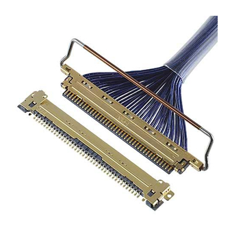
ASM-08003
Document No.
8
S19014
7
S18632
6
S18401
5
S17910
Rev.
ECN
Confidential C
CABLINE
Part No. 20453-#**T-###
Assembly Manual
January 8, 2019
October 1, 2018
July 2, 2018
December 12, 2017
Date
-VS PLUG
®
Y.Miyazaki
Y.Miyazaki
A.Koyanagi
Y.Miyazaki
Prepared by
I-PEX Inc.
1 / 22
T.Masunaga
-
T.Masunaga
T.Masunaga
Checked by
QKE-DFFDE09-04 REV.8
H.Ikari
H.Ikari
H.Ikari
H.Ikari
Approved by
Advertisement

Related Manuals for I-PEX CABLINE-VS PLUG


Summary of Contents for I-PEX CABLINE-VS PLUG
- Page 1 Y.Miyazaki T.Masunaga H.Ikari S18632 October 1, 2018 Y.Miyazaki H.Ikari S18401 July 2, 2018 A.Koyanagi T.Masunaga H.Ikari S17910 December 12, 2017 Y.Miyazaki T.Masunaga H.Ikari Rev. Date Prepared by Checked by Approved by Confidential C I-PEX Inc. QKE-DFFDE09-04 REV.8 1 / 22...
- Page 2 ® 1.目的 (Purpose): CABLINE-VS PLUG において、ケーブルの半田付け手順及び SHELL-A, PULL-BAR の組み付けについて 明記する。 This manual is to explain the soldering method / process of the CABLINE-VS PLUG with cable, and assembly of SHELL-A, PULL-BAR. 2.適用コネクタ (Applicable connector): Name : CABLINE-VS PLUG Parts No. : Set P/N CABLE ASS’Y...
- Page 3 Document No. CABLINE -VS PLUG Assembly Manual ASM-08003 ® 4. パルスヒート条件[推奨] (Recommended pulse heat condition) MICRO-COAX Discrete ①アイドリング温度 (Idle temp.) 150℃ 150℃ ②1 ヒート設定温度 (1 heat temp.) 220℃ 220℃ ③ 〃 立ち上がり時間 ( 〃 rise time) 0.5sec. 0.5sec. ④ 〃 維持時間 ( 〃 holding time) 3.0sec.
- Page 4 Document No. CABLINE -VS PLUG Assembly Manual ASM-08003 ® 5.作業手順 (Work procedures): 5-1. 芯線の半田付け (Soldering of center-conductor) ①まず適合ケーブルの端末処理形状を下図の様にして下さい。 The cables have to be fabricated as shown below in advance of soldering. DIMENSION-A Pos. 9.50 14.50 19.50 24.50 RECOMMENDED MICRO COAX CABLE DIMENSION MICRO COAX CABLE DIMENSION 0.15 0.12...
- Page 5 Document No. CABLINE -VS PLUG Assembly Manual ASM-08003 ® DIMENSION-A Pos. 9.50 14.50 19.50 24.50 RECOMMENDED DISCRETE CABLE DIMENSION DISCRETE CABLE DIMENSION 0.24 0.192 0.15 DISCRETE CABLE AWG #** Confidential C 5 / 22...
- Page 6 Document No. CABLINE -VS PLUG Assembly Manual ASM-08003 ® DIMENSION-A Pos. 9.50 14.50 19.50 24.50 RECOMMENDED TWINCOAX DIMENSION TWINCOAX CABLE AWG #40 Confidential C 6 / 22...
- Page 7 Document No. CABLINE -VS PLUG Assembly Manual ASM-08003 ® ②ディスペンサー等でコンタクトにフラックスを塗布し、全コンタクトにフラックスが塗布されたことを確認して下さい。 Apply flux to contact by the dispenser etc., and please confirm all contacts were applied flux. Applying Flux area Photo.1 After applying flux ※ Photo.2 のようにフラックスを塗布し過ぎないで下さい。フラックスの飛散及び フラックス過多による嵌合部への染み出しの原因となります。 Please do not apply flux too much like Photo.2. It can cause flux splash or leak to the mating area. Photo.2 Extra flux ※洗浄機等によるフラックスの洗浄は行わないで下さい。フラックスが嵌合部に付着する可能性が...
- Page 8 Document No. CABLINE -VS PLUG Assembly Manual ASM-08003 ® ③コネクタに半田バーをセットする。 Pre-set and locate solder bar at center of connector (HSG ASS’Y). Solder Bar Fig.1 Set of solder bar ④ケーブルをセットする。Set the cable. ※ディスクリートケーブルのセットは芯線と SHELL が接触する恐れがある為、 Fig.3 のように 0.2MAX を守ってください ※Setting discrete cable is to protect 0.2MAX. as Fig.3. There is danger that Center Conductor touch SHELL. Fig.2 Set of cable Fig.3 Setting Discrete Cable Confidential C...
- Page 9 Document No. CABLINE -VS PLUG Assembly Manual ASM-08003 ® ⑤芯線をパルスヒートにて半田付けする。 半田付け状態は、下記 Photo.3 参照。 Center-conductors are soldered with pulse heater. See photo.3 of soldering condition. Photo.3 AWG#40 注意:PLUG HSG ASS’Y の SHELL 底面には、Fig.4 の箇所に凸形状を設けておりますので、 パルスヒートの受け JIG には、干渉しないように凸形状の逃がしを設けてください。 Caution: The SHELL bottom side of PLUG HSG ASS’Y has convex shape at the points shown in Fig.4, so please make escape shape on the receiving jig of the pulse heater to prevent interference.
- Page 10 Document No. CABLINE -VS PLUG Assembly Manual ASM-08003 ® ※仮に手半田等で半田量が多く SHELL-A との短絡の恐れがある場合は、後述の SHELL-A の 組み付け前に SHELL-A に絶縁テープを貼る等の処置を行ってください。 ※When there is much quantity of solder in hand soldering, and there might be the short circuit with SHELL-A, put an insulating tape in SHELL-A before assembly of SHELL-A. 注意:芯線の半田付け後、図...
- Page 11 Document No. CABLINE -VS PLUG Assembly Manual ASM-08003 ® ◆絶縁テープ厚(Insulating tape thickness) t=0.06mm 【SHELL-A P/N:2574-#**】 (0.64) 0.8+0.2/-0 絶縁テープ/ Insulating tape SHELL-A の先端側凸部には掛からないようにお願いします。 SHELL-A の浮きが発生する可能性があります。 Please avoid touching the convex point on SHELL-A fore-end. It might cause the SHELL-A float. 絶縁テープ/ Insulating tape 20P:9.70、30P:14.70、40P:19.70、50P:24.70 Confidential C 11 / 22...
- Page 12 Document No. CABLINE -VS PLUG Assembly Manual ASM-08003 ® 5-2.SHELL-A 取り扱い注意事項 (Cautions in treating SHELL-A) SHELL-A はキャリア付きリール状態にて納品されます。SHELL-A をキャリアから折り取る手順を明記します。 SHELL-A is delivered in the reel with a carrier. The following is the method to cut SHELL-A from Carrier. ① キャリアを金属用はさみ等を用いて下左写真の Cut Line(緑線)にて切断する。 Cut carrier on the cut line of a lower left picture (green line) by a scissors for metal.
- Page 13 Document No. CABLINE -VS PLUG Assembly Manual ASM-08003 ® View A View B Without burrs View A View B Photo.7 After cut Plug SHELL-A ノッチ部状態(Detail of Notch) Photo 8. Bottom side view Photo 9. Upper side view 注意:下写真(赤矢印)の様に無理やり引っ張ったりして切り離すとバリや変形の原因になります。 Caution: By pulling like a lower photo to cut off by force (Red arrow direction), burrs and transformation can be caused.
- Page 14 Document No. CABLINE -VS PLUG Assembly Manual ASM-08003 ® 5-3. PULL-BAR 組み付け (Assembly of PULL-BAR) ・In case of WITH PULL-BAR(CABLE ASS’Y P/N:20453-0**T-#1) & WITH INSULATION PULL-BAR(CABLE ASS’Y P/N:20453-0**T-#3). Fig.6-1 の様に PULL-BAR(pull-tape※1)を HOUSING ASS’Y へ組み付ける。 PULL-BAR(pull-tape※1) is assembled to HOUSING ASS’Y. PULL-BAR P/N: PULL-BAR P/N: 2576-0**...
- Page 15 Document No. CABLINE -VS PLUG Assembly Manual ASM-08003 ® 推奨 Pull-tape(Recommended pull-tape) ・寺岡製作所製絶縁テープ TERAOKA’s INSULATION TAPE No.650S(#50) thickness=0.08mm Positions 13.0 18.0 23.0 28.0 14.45 19.45 24.45 29.45 Unit:mm Fig.6-2 Pull-tape 推奨寸法(Pull-tape Recommended dimension) 注意 1:Pull-tape は推奨寸法で製作をお願い致します。下図の様に極端に Pull-tape が小さい場合、 Pull-BAR 変形の原因になります。 Caution1 : Pull-tape dimensions shall be based on recommended dimensions.
- Page 16 Document No. CABLINE -VS PLUG Assembly Manual ASM-08003 ® 注意 2:Pull-tape を下図の様に、矢印方向へ力を加えないでください。PULL-BAR 変形の原因になります。 Caution 2 : Do not apply force toward arrowed directions. It may deform the pull-bar. Fig.6-4 PULL-BAR 取扱いにおける注意事項 (Caution of handling of pull-bar) 注意 3:下図の様に SHELL-A を組み付け後、PULL-BAR を取り付ける事はしないでください。 PULL-BAR 変形の原因になります。...
- Page 17 Document No. CABLINE -VS PLUG Assembly Manual ASM-08003 ® 5-4. SHELL-A 組み付け (Assembly of SHELL-A) ① Fig.7-1 の様に HOUSING ASS’Y の上側から SHELL-A の青斜線部(Fig.7-2)を押し、組み付ける。 赤斜線部のみを押して SHELL-A を挿入すると、先端ロック部が変形し、未ロックの原因になります。 Place the SHELL-A on the upper surface of the HOUSING ASS’Y and push only the blue shaded areas to assemble them.
- Page 18 Document No. CABLINE -VS PLUG Assembly Manual ASM-08003 ® ②SHELL-A が正常に組み立てられているか確認する。 SHELL どうしのロックが掛かっているか。(Fig.8★部) shell A t oShell B 判定基準は Fig.9 を参照してください。 It confirms whether SHELL-A is being assembled normally. Whether SHELL locks are being assembled normally. (Fig.8★ point) Please refer to Fig.9 for shell-A lock criteria. ★Point ★Point Fig.8 The assembly confirmation of SHELL-A...
- Page 19 Document No. CABLINE -VS PLUG Assembly Manual ASM-08003 ® SHELL-A 取り付け後の注意点 : SHELL-A を組み付け後、PULL-BAR を裏面側へ回さないでください。(Fig.10 参照) SHELL-A のロックが外れしまう可能性があります。 Precaution: Do not push shell-A toward bottom side as shown in Fig. 10 , or this may unlock shell-A. Fig.10 Improper handling of shell-A Confidential C 19 / 22...
- Page 20 Document No. CABLINE -VS PLUG Assembly Manual ASM-08003 ® ③SHELL-A,B と GND BAR を半田コテにて半田付けする。 (Fig.11,12◆部) 半田の高さ(半田量)の限度は Fig.15 参照。 半田コテの条件は、8 頁参照。 ※ディスクリートケーブル結線時は Fig.11,12◆部の半田付けできません。 SHELL-A ,B and GND BAR are soldered with the soldering iron. (Fig.11,12◆ point) Refer to Fig.15 for a limit of the solder height. Conditions of Soldering iron refer to sheet 8.
- Page 21 Document No. CABLINE -VS PLUG Assembly Manual ASM-08003 ® ④SHELL-A と SHELL-B を半田コテにて半田付けする。 (Fig.13◆部) 半田コテの条件は、8 頁参照。 ※ディスクリートケーブル結線時においても Fig.13◆部の半田付けは必要です。 SHELL-A and SHELL-B are soldered with the soldering iron. (Fig.13◆ point) Conditions of Soldering iron refer to sheet 8. ※In case of soldering discrete cable, soldering at Fig.13◆point is necessary. ◆Point Fig.13 Soldering of SHELL-A and SHELL-B 半田付け時の注意点:...
- Page 22 Document No. CABLINE -VS PLUG Assembly Manual ASM-08003 ® 5-5. ケーブル固定 (Cable fixation) ケーブル端末部を接着剤にて固定する。 接着剤 : LOCTITE 352 Fix the cable terminal part with the bond. Bond: LOCTITE 352 1.7~2.8mm 1.7~2.8mm Fig.14 Bonding Fig.15 Soldering & Bonding Confidential C 22 / 22...
Need help?
Do you have a question about the CABLINE-VS PLUG and is the answer not in the manual?
Questions and answers