Table of Contents
Advertisement
Quick Links
Advertisement
Table of Contents

Related Manuals for New England Arbors Trellis Pergola


Summary of Contents for New England Arbors Trellis Pergola
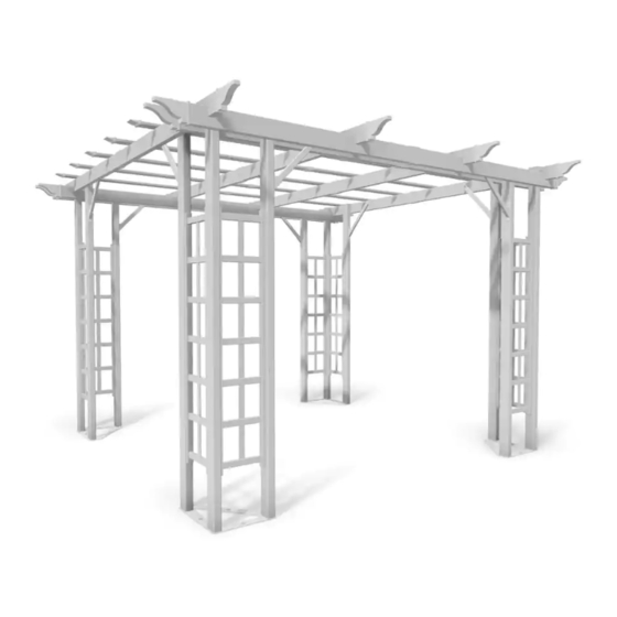
- Page 1 10x10 Trellis Pergola A S S E M B L Y G U I D E Ver 1.0-122714...
-
Page 2: Table Of Contents
Ta b l e o f Co n t e n t s PAGE Biltmore Pergola Introduction & Overview……………………………..........………..Pergola Materials Overview………………………. -
Page 3: Introduction & Overview
I n t r o d u c t i o n & O ve r v i e w Getting Started Restriction of Use First off, allow us to say thank you for the investment you have made in one This product is not designed to carry additional of our fine pergola kits. - Page 4 Biltmore Pergola Materials Overview 1. Posts - Long (8) 2. Posts - Short (4) 3. Pergola Beams (8) 4. Pergola Rafters (8) 5. Rafter & Beam Decorative End Caps (16) 6. Rafter & Beam Joiners (8) 7. Trellis Posts (16) 8.
- Page 5 Biltmore Pergola Materials Breakdown Check Boxes (Total of 4) for These Contents In the event of missing or defective parts please call our customer service dept. at 1 800 282 9346, ext #20 (Mon. to Fri. 8:00 AM to 4:00 PM EST). 1.
-
Page 6: Pergola Additional Materials List
Pergola Additional Materials List Hardware (in plastic bag) NOTE: WE HAVE INCLUDED 10% EXTRA SCREWS BEYOND WHAT IS IDENTIFIED BELOW. All Screws Included with this Kit are Self-Auguring. A. Vinyl Weld Glue (2) B. 1 1/2” Self-Auguring Stainless Steel Screws (64) (To fasten trellis assembly to pergola posts) C. -
Page 7: Side Panel Trellis Assembly
Pergola Assembly S T E P O N E Side Panel Trellis Assembly One by one, insert five Middle Trellis Horizontal Rails over the Trellis vertical Slat as shown. Excess force should not be used. Slide the End Trellis Horizontal Rails over the assembly as shown. -
Page 8: Corner Post Assembly
Pergola Assembly S T E P T W O Corner Post Assembly Lay ALL the posts on its side as shown and create a mark 12 inches from the one end. Separate the LONG POSTS from the SHORT POSTS. 1 2 i n Place one of the trellis assembly from the previous step on the narrow side of the long post and align the one end to the pencil mark. - Page 9 S T E P T H R E E Left and Right Corner Post Assembly There are Left and Right corner assemblies (2 each) as shown aside: The assembly process is very similar, the only diference between the two is which post the second trellis assembly is attached to. (The left or right side of the assembly) Place a trellis assembly on one of the post and fasten with four 1-1/2”...
-
Page 10: Vinyl Beam Assembly
S T E P F O U R Aluminium block should face up Vinyl Beam Assembly Insert two short aluminium stiffener into one long aluminium stiffener to create full length piece. Repeat so you have four full length beams. Insert one end of the beam into the joiner. Push firmly until the extrusion bottoms out inside the joiner. -
Page 11: Vinyl Rafter Assembly
S T E P F I V E Vinyl Rafter Assembly Insert one end of the rafter into the joiner. Push firmly until the extrusion bottoms out inside the joiner. Insert one aluminium stiffener (with aluminium block facing up), into the pocket of the vinyl rafter past the joiner. Push until aluminium block is centered about the joiner. -
Page 12: Vinyl Beams & Rafters Placement
S T E P S I X Vinyl Beams & Rafters Placement Slide the four corner post assemblies over mounting plates as shown. Space the post assemblies out using dimensions shown. Measurements are taken between posts. 8 2 in With a helper, raise the beam assemblies (one at a time) and butt them up against the posts as shown. - Page 13 S T E P S I X ( Co n t ’d ) Vinyl Beams & Rafters Placement 3 9 in 3 9 in 3 9 in With a helper, place the rafter assemblies onto the beam assemblies. Excessive force should not be used. End rafters should butt up against the posts.
-
Page 14: Pergola Brace Assembly Placement
Holes S T E P S E V E N Pergola Brace Assembly & Placement Insert the brace into the bracket as shown. Note the location of the two holes. Pressure fit the end cap onto the brace. Repeat for all 8 braces. Re-install the brace and fasten into place using one Place brace assembly onto the post as shown. -
Page 15: Shade Slat Assembly & Installation
S T E P E I G H T Shade Slat Assembly & Installation Insert two shade slats into a shade slat joiner as shown. Apply a bead of vinyl glue to the inside of the shade slat end cap and firmly attach to the end of the shade slat Repeat for all 6 shade slats. -
Page 16: Pergola Mounting
S T E P N I N E Pergola Mounting Important step: ensure that your ground is level. This can be This pergola has been designed to be easy to install and anchor to the ground. If you are in a high wind location and require more accomplished by a combination of building up the ground with stability, please see the next page on how to install the posts into soil and/or digging as necessary. -
Page 17: Wood Post Layout & Installation For In-Ground Application
Wood Post Layout & Installation for In-Ground Application Follow these instructions to install this pergola in the ground. Overhead View Post location and placement is the most critical step in the overall installation process. Please double check for the 113 3/16 in possibility of any underground utilities such as sprinkler, gas 15 1/2 in 15 1/2 in... -
Page 18: Pergola Installation On Deck (With Access To Under The Deck)
Pergola Installation on deck (with access to under the deck) Pergola installation with this menthod can and should be done AFTER the pergola is fully assembled. S T E P O N E Place the fully assembled pergola (including the mounting plates) to the desired location and make sure pergola posts are standing square relative to each other. -
Page 19: Pergola Installation On Deck (With No Access To Under The Deck)
Pergola Installation on deck (with no access to under the deck) Pergola installation with this menthod can and should be done AFTER the pergola is fully assembled. S T E P O N E Place the fully assembled pergola (including the mounting plates) to the desired location and make sure pergola posts are standing square relative to each other. -
Page 20: Pergola Installation On Existing Concrete Pad
Pergola Installation on Existing Concrete Pad Pergola installation with this menthod can and should be done AFTER the pergola is fully assembled. S T E P O N E Place the fully assembled pergola (including the mounting plates) to the desired location and make sure pergola posts are standing square relative to each other. -
Page 21: Additional Installation Note
Additional Installation Note If there is too much sway in the pergola, you may also purchase “ready-mix” cement and pour it down the posts - DRY - and then add water down the posts (consult cement packaging for cement- water ratio). This will help lock the posts and footings together.
Need help?
Do you have a question about the Trellis Pergola and is the answer not in the manual?
Questions and answers