Table of Contents
Advertisement
Quick Links
PZ250E
E-836.1G Piezo Amplifier
User Manual
Version: 1.0.1
Date: 10.03.2014
This document describes the following
product:
E-836.1G
Piezo Amplifier, 1 Channel, Bench-Top, -30
to 130 V
Physik Instrumente (PI) GmbH & Co. KG · Auf der Römerstr. 1 76228 Karlsruhe, Germany
Telephon +49 721 4846-0 · Telefax +49 721 4846-1019 · E-Mail info@pi.ws
Advertisement
Table of Contents

Related Manuals for PI E-836.1G


Summary of Contents for PI E-836.1G
- Page 1 This document describes the following product: E-836.1G Piezo Amplifier, 1 Channel, Bench-Top, -30 to 130 V Physik Instrumente (PI) GmbH & Co. KG · Auf der Römerstr. 1 76228 Karlsruhe, Germany Telephon +49 721 4846-0 · Telefax +49 721 4846-1019 · E-Mail info@pi.ws...
- Page 2 With regard thereto, Physik Instrumente (PI) GmbH & Co. KG retains all the rights. Use of said text, photographs and drawings is permitted only in part and only upon citation of the source.
-
Page 3: Table Of Contents
Rear Panel ..................9 Scope of Delivery ....................10 Unpacking Installation General Notes on Installation ................13 Connecting the E-836.1G to the Protective Earth Conductor ......13 Connecting the Power Supply to the E-836.1G ..........14 Connecting the Stage ..................15 Connecting the Control Input Voltage ..............15 Start-Up General Notes on Start-Up .................17... - Page 4 Troubleshooting Customer Service Technical Data 10.1 Specifications......................27 10.1.1 Data Table ..................27 10.1.2 Maximum Ratings ................28 10.1.3 Ambient Conditions and Classifications ...........28 10.2 Operating Limits ....................29 10.3 Dimensions ......................30 10.4 Block Diagrams ....................31 10.5 Pin Assignment ....................31 10.5.1 PZT Socket ..................31 10.5.2 24 VDC Power Supply Connection...........31 Old Equipment Disposal...
-
Page 5: About This Document
Downloading Manuals ....................3 1.1 Goal and Target Audience of this User Manual This manual contains information on the intended use of the E-836.1G. It assumes that the reader has a fundamental understanding of basic servo systems as well as motion control concepts and applicable safety procedures. -
Page 6: Other Applicable Documents
The devices and software tools which are mentioned in this documentation are described in their own manuals. The latest versions of the user manuals are available for download (p. 3) on our website. Component Document Analog Controller LabView Driver Library PZ181E Software Manual Version: 1.0.1 PZ250E E-836.1G Piezo Amplifier... -
Page 7: Downloading Manuals
(e.g. Hexapod systems and electronics that are delivered with a CD), access to the manuals is password-protected. The password is stored on the CD. Download freely accessible manuals 1. Open the website http://www.pi-portal.ws. 2. Click Downloads. 3. Click the corresponding category (e.g. E Piezo Drivers & Nanopositioning Controllers) 4. -
Page 9: Safety
The E-836.1G is built according to state-of-the-art technology and recognized safety standards. Improper use can result in personal injury and/or damage to the E-836.1G. Only use the E-836.1G for its intended purpose, and only use it if it is in a good working order. -
Page 10: Organizational Measures
Add all information given by the manufacturer to the user manual, for example supplements or Technical Notes. If you pass the E-836.1G on to other users, also turn over this user manual as well as all other relevant information provided by the manufacturer. -
Page 11: Product Description
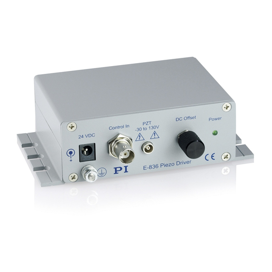
3 Product Description Product Description In this Chapter Product View ......................... 7 Scope of Delivery ......................10 3.1 Product View 3.1.1 Front Panel Figure 1: E-836.1G piezo amplifier, front view Labeling Type Function 24 VDC Barrel connector Connection for the supply voltage... - Page 12 1-turn potentiometer, adds 0 to 10 V to control input voltage Power Display of the ready state: green/off Green: E-836.1G is ready for operation Off: E-836.1G is not ready for operation Manufacturer's logo E-836 Piezo Product Description Driver CE conformity mark Version: 1.0.1 PZ250E...
-
Page 13: Rear Panel
3 Product Description 3.1.2 Rear Panel Figure 2: E-836.1G piezo amplifier, rear view Labeling Function Data matrix code (example; contains the serial number) E-836.1G Product name Manufacturer's logo 113064443 Serial number (example), individual for each E-836.1G Meaning of the places (counting from left): 1 = internal information,... -
Page 14: Scope Of Delivery
100 to 240 VAC and voltage frequencies of 50 or 60 Hz, with barrel connector 3763 Power cord PZ250E User manual for E-836.1G (this document) E500T0011 Technical note for the LabVIEW analog driver Version: 1.0.1 PZ250E E-836.1G Piezo Amplifier... -
Page 15: Unpacking
4 Unpacking Unpacking 1. Unpack the E-836.1G with care. 2. Compare the contents against the items covered by the contract and against the packing list. 3. Inspect the contents for signs of damage. If parts are missing or you notice signs of damage, contact PI immediately. -
Page 17: Installation
Observe the applicable standards for mounting the protective earth conductor. Prerequisite You have read and understood the general notes on installation (p. 13). The E-836.1G is switched off, i. e. the power supply is not connected to the power socket via the power cord. Tools and accessories ... -
Page 18: Connecting The Power Supply To The E-836.1G
Alternatively: Sufficiently dimensioned power supply Included power cord Alternatively: Sufficiently dimensioned power cord Connecting the power supply to the E-836.1G Connect the power supply to the 24 VDC connection of the E-836.1G. Version: 1.0.1 PZ250E E-836.1G Piezo Amplifier... -
Page 19: Connecting The Stage
Voltage connection: Via LEMO connector Connecting the stage Connect the voltage connection of the stage to the PZT -30 to 130 V LEMO socket of the E-836.1G. 5.5 Connecting the Control Input Voltage INFORMATION The control signal for the output piezo voltage is the sum of the following signals: ... - Page 20 Signal source for the control input voltage. The control input voltage can also be a computer-generated analog signal (e. g. from a data acquisition board). You can use the PI LabVIEW analog drivers to generate the analog signal (see E500T0011 Technical Note and the PZ181E manual).
-
Page 21: Start-Up
If a protective earth conductor is not or not properly connected, dangerous touch voltages can occur on the E-836.1G in the case of malfunction or failure of the system. If touch voltages exist, touching the E-836.1G can result in serious injury or death from electric shock. -
Page 22: Switching On The E-836.1G
INFORMATION When it is switched off, the E-836.1G generates a voltage spike at the output for the piezo voltage. A connected stage will execute a corresponding motion, which can be noticeable as a clicking sound. This behavior is unproblematic and does not affect the stage. -
Page 23: Executing Motions
You have mounted the stage according to the description in the corresponding user manual. You have connected the stage to the E-836.1G (p. 15). When the stage is operated via a control input voltage: You have connected a signal source to the E-836.1G (p. -
Page 25: Maintenance
Prevent cleaning fluid from entering the case. When necessary, clean the surfaces of the E-836.1G case with a cloth that has been lightly dampened with a mild cleanser or disinfectant. Do not use any organic solvents. - Page 27 (Control In BNC socket). If the problem that occurred with your system is not listed in the table above or cannot be solved as described, contact our customer service department (p. 25). E-836.1G Piezo Amplifier PZ250E Version: 1.0.1...
- Page 29 9 Customer Service Customer Service For inquiries and orders, contact your PI sales engineer or send us an e-mail (mailto:info@pi.ws). If you have questions concerning your system, have the following information ready: Product codes and serial numbers of all products in the system ...
-
Page 31: Technical Data
5 to 50 °C Overtemp protection Deactivation at 85 °C °C Operating voltage 24 ±10 %, included: external power supply, 24 V / 2.0 A Power consumption (max.) Current consumption (max.) 0.65 Ask about custom designs! E-836.1G Piezo Amplifier PZ250E Version: 1.0.1... -
Page 32: Maximum Ratings
10 Technical Data 10.1.2 Maximum Ratings The E-836.1G is designed for the following operating data: Input on: Maximum Operating Operating Fused Current Voltage Frequency Consumption Barrel 24 V connector socket 10.1.3 Ambient Conditions and Classifications The following ambient conditions and classifications must be observed for the E- 836.1G:... -
Page 33: Operating Limits
10 Technical Data 10.2 Operating Limits The following diagram shows the operating limits for various piezo loads. The curve values are capacitance values in μF. Figure 3: Operating limits E-836.1G Piezo Amplifier PZ250E Version: 1.0.1... -
Page 34: Dimensions
10 Technical Data 10.3 Dimensions Dimensions in mm. Note that the decimal places are separated by a comma in the drawings. Figure 4: E-836.1G, dimensions in mm Version: 1.0.1 PZ250E E-836.1G Piezo Amplifier... -
Page 35: Block Diagrams
10 Technical Data 10.4 Block Diagrams Figure 5: E-836.1G block diagram 10.5 Pin Assignment 10.5.1 PZT Socket LEMO socket EPK.00.250.NTN, 2-pin, for transmission of the piezo voltage: Outer contact: PZT ground (connected with the case) Inner contact: PZT+ (–30 to +130 V) 10.5.2 24 VDC Power Supply Connection... -
Page 37: Old Equipment Disposal
Instrumente (PI) GmbH & Co. KG ensures environmentally correct disposal of old PI equipment that was first put into circulation after 13 August 2005, free of charge. If you have old PI equipment, you can send it postage-free to the following address: Physik Instrumente (PI) GmbH & Co. KG Auf der Römerstr. -
Page 39: Appendix
Relative humidity The following diagrams show how the individual factors influence the lifetime of the actuator. Figure 6: Dependency of the mean time between failure (MTTF) of a PICMA® actuator on the applied voltage E-836.1G Piezo Amplifier PZ250E Version: 1.0.1... - Page 40 Figure 7: Dependency of the mean time between failure (MTTF) of a PICMA® actuator on the ambient temperature Figure 8: Dependency of the mean time between failure (MTTF) of a PICMA® actuator on the relative humidity Version: 1.0.1 PZ250E E-836.1G Piezo Amplifier...
- Page 41 The recommended maximum range for the input voltage of the E-836.1G is therefore –2 to +12 V. This results in a piezo voltage range of –20 to 120 V (in open-loop operation). The input voltage range can be expanded from –3 to +13 V (the piezo voltage is then in the range of -30 to...
-
Page 43: Ec Declaration Of Conformity
12 Appendix 12.2 EC Declaration of Conformity For the E-836.1G, an EC Declaration of Conformity has been issued in accordance with the following European directives: 2006/95/EC, Low Voltage Directive 2004/108/EC, EMC Directive 2011/65/EU, RoHS Directive The applied standards certifying the conformity are listed below.
Need help?
Do you have a question about the E-836.1G and is the answer not in the manual?
Questions and answers