
Related Manuals for ABB SafeGear MCC


Summary of Contents for ABB SafeGear MCC
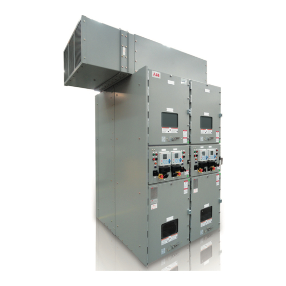
- Page 1 — ELECTRIFICATION PRODUCTS SafeGear® Motor Control Center Arc-resistant metal-clad construction Installation, operation and maintenance manual...
- Page 2 — Medium voltage SafeGear® Motor Control Center: controlling energy for a safe world...
-
Page 3: Table Of Contents
— Table of contents General instructions 001 – 002 Safety notes and warnings 002 – 003 Receiving, handing and storage Location site preparation 004 – 009 Indoor installation 010– 012 Testing and final inspection 012 – 013 Putting into service 013 –... -
Page 4: General Instructions
The instructions are general in nature. They cover requirements for installation, setup, checkout and maintenance as applied to ABB medium voltage Motor Control Centers (MCC). These instructions do not attempt to cover all variations and combinations of equipment and installations. Information on particular installations appears in the following: •... -
Page 5: Receiving, Handing And Storage
If there is damage from improper handling, file a claim for damages at once with the carrier and notify ABB. Note: ABB standard shipments are “FOB Factory.” ABB is not responsible for damage after delivery of the equipment to the carrier unless otherwise... -
Page 6: Location Site Preparation
S A F E G E A R ® M O T O R C O N T R O L C E N T E R /A R C - R E S I S TA N T M E TA L - C L A D C O N S T R U C T I O N Storage Place the equipment on the shipping base. -
Page 7: Indoor Installation
I N S TA L L AT I O N , O P E R AT I O N A N D M A I N T E N A N C E M A N U A L — Indoor Installation General WARNING... - Page 8 S A F E G E A R ® M O T O R C O N T R O L C E N T E R /A R C - R E S I S TA N T M E TA L - C L A D C O N S T R U C T I O N Towing - use chains rated for safe handling of the shipping splits.
- Page 9 Following the removal of the shipping bases, the MCC units should be secured to the floor either by bolting per the guidelines outlined on the ABB factory drawings. Welding is not recommended and no guidelines exist for attachment using this method.
- Page 10 S A F E G E A R ® M O T O R C O N T R O L C E N T E R /A R C - R E S I S TA N T M E TA L - C L A D C O N S T R U C T I O N If shorting terminal blocks are used, review the connection diagram that was shipped with the unit, for position of shorting screws.
- Page 11 Remove barriers to access the main bus compartment. Bolt the main bus together using supplied hardware. Conductivity of a bolted joint depends on the pressure or torque applied. Note: All bolted joints must be torqued per ABB specifications – see Appendix B.
- Page 12 S A F E G E A R ® M O T O R C O N T R O L C E N T E R /A R C - R E S I S TA N T M E TA L - C L A D C O N S T R U C T I O N Secondary and control connections The MCC was wired in the factory in accordance with the Project specific Connection Diagrams.
-
Page 13: Testing And Final Inspection
I N S TA L L AT I O N , O P E R AT I O N A N D M A I N T E N A N C E M A N U A L — Testing and final inspection Testing DANGER... - Page 14 S A F E G E A R ® M O T O R C O N T R O L C E N T E R /A R C - R E S I S TA N T M E TA L - C L A D C O N S T R U C T I O N Make sure all contactor assemblies are open (OPEN).
-
Page 15: Putting Into Service
I N S TA L L AT I O N , O P E R AT I O N A N D M A I N T E N A N C E M A N U A L Final inspection DANGER The contactor or cutout device of the local control power circuit must be opened when is used a separated control power source. -
Page 16: Standard Construction
S A F E G E A R ® M O T O R C O N T R O L C E N T E R /A R C - R E S I S TA N T M E TA L - C L A D C O N S T R U C T I O N All contactors must be in “DISCONN.”... - Page 17 I N S TA L L AT I O N , O P E R AT I O N A N D M A I N T E N A N C E M A N U A L Fig. 6 Contactor compartment Fig.
- Page 18 S A F E G E A R ® M O T O R C O N T R O L C E N T E R /A R C - R E S I S TA N T M E TA L - C L A D C O N S T R U C T I O N —...
-
Page 19: Contactor Compartment Operation
I N S TA L L AT I O N , O P E R AT I O N A N D M A I N T E N A N C E M A N U A L — Contactor compartment operation Fig. - Page 20 S A F E G E A R ® M O T O R C O N T R O L C E N T E R /A R C - R E S I S TA N T M E TA L - C L A D C O N S T R U C T I O N Fig.
- Page 21 I N S TA L L AT I O N , O P E R AT I O N A N D M A I N T E N A N C E M A N U A L 4. Finally, check that thinner tongue bellow of the This tongue shall be aligned to be received in the secondary connector on the controller truck is also female part located just bellow of the secondary...
-
Page 22: Maintenance
S A F E G E A R ® M O T O R C O N T R O L C E N T E R /A R C - R E S I S TA N T M E TA L - C L A D C O N S T R U C T I O N NOTICE Put the 10-32 UNF screw in place after 10-32... - Page 23 I N S TA L L AT I O N , O P E R AT I O N A N D M A I N T E N A N C E M A N U A L Semi annual inspection Perform a thorough inspection of the MCC at least semiannually.
- Page 24 End of life of product ABB products are manufactured to meet or exceed the standards of compliance for quality and environmental management systems in accordance with ISO 9001 and ISO 14001. All of these items can be supplied with a certificate of quality.
- Page 25 In no event will ABB be responsible to the user in contract, in tort (including negligence), strict liability or otherwise for any special, indirect, incidental or consequential damage or loss whatsoever including but not...
-
Page 26: Plenum Installation
S A F E G E A R ® M O T O R C O N T R O L C E N T E R /A R C - R E S I S TA N T M E TA L - C L A D C O N S T R U C T I O N —... - Page 27 I N S TA L L AT I O N , O P E R AT I O N A N D M A I N T E N A N C E M A N U A L 2. 3/8”-16 1.
- Page 28 S A F E G E A R ® M O T O R C O N T R O L C E N T E R /A R C - R E S I S TA N T M E TA L - C L A D C O N S T R U C T I O N General dimensions (in[mm])
- Page 29 UNDERSTAND THAT THESE WARNINGS COULD NOT COVER ALL CONCEIVABLE WAYS IN WHICH SERVICE, WHETHER OR NOT RECOMMENDED BY ABB, MIGHT BE DONE OR OF THE POSSIBLE HAZARDOUS CONSEQUENCES OF EACH CONCEIVABLE WAY, NOR COULD ABB INVESTIGATE ALL SUCH WAYS. ANYONE...
- Page 30 S A F E G E A R ® M O T O R C O N T R O L C E N T E R /A R C - R E S I S TA N T M E TA L - C L A D C O N S T R U C T I O N Scope/Introduction This procedure applies to the assembly of the ABB MCC 2.5 frames at the customer site. Disclaimer This document was created with the intent of providing a general instruction guide.
- Page 31 I N S TA L L AT I O N , O P E R AT I O N A N D M A I N T E N A N C E M A N U A L Procedure —...
- Page 32 S A F E G E A R ® M O T O R C O N T R O L C E N T E R /A R C - R E S I S TA N T M E TA L - C L A D C O N S T R U C T I O N View front (left frame) —...
- Page 33 I N S TA L L AT I O N , O P E R AT I O N A N D M A I N T E N A N C E M A N U A L — 07 Remove the rear covers of the back frame.
- Page 34 S A F E G E A R ® M O T O R C O N T R O L C E N T E R /A R C - R E S I S TA N T M E TA L - C L A D C O N S T R U C T I O N —...
- Page 35 Appendix B Main bus assembly Scope/Introduction This procedure applies to the assembly of the SafeGear MCC main bus at the customer site. Disclaimer This document was created with the intent of providing a general instruction guide. Models shown in this document may not match exactly the product you received.
- Page 36 S A F E G E A R ® M O T O R C O N T R O L C E N T E R /A R C - R E S I S TA N T M E TA L - C L A D C O N S T R U C T I O N —...
- Page 37 I N S TA L L AT I O N , O P E R AT I O N A N D M A I N T E N A N C E M A N U A L Procedure —...
- Page 38 S A F E G E A R ® M O T O R C O N T R O L C E N T E R /A R C - R E S I S TA N T M E TA L - C L A D C O N S T R U C T I O N —...
- Page 39 I N S TA L L AT I O N , O P E R AT I O N A N D M A I N T E N A N C E M A N U A L — 05 Slide the main bus bars through the through three openings in the bus...
- Page 40 Use the torque wrench to tighten all ½” – 13 UNC bolts, they must be tightened to ABB specifications - see Appendix D. spacer — spacer Bolts —...
- Page 41 I N S TA L L AT I O N , O P E R AT I O N A N D M A I N T E N A N C E M A N U A L — 09 Reinstall all the bus boots.
- Page 42 S A F E G E A R ® M O T O R C O N T R O L C E N T E R /A R C - R E S I S TA N T M E TA L - C L A D C O N S T R U C T I O N —...
- Page 43 — Appendix C Wiring interconnections Scope/Introduction This procedure applies to the installation of wiring interconnects for SafeGear MCC at the customer site. Disclaimer This document was created with the intent of providing general instructions. Models shown in this document may not match exactly the product you received.
- Page 44 S A F E G E A R ® M O T O R C O N T R O L C E N T E R /A R C - R E S I S TA N T M E TA L - C L A D C O N S T R U C T I O N —...
- Page 45 I N S TA L L AT I O N , O P E R AT I O N A N D M A I N T E N A N C E M A N U A L — 03 Route the wires according to the interconnect diagram.
- Page 46 S A F E G E A R ® M O T O R C O N T R O L C E N T E R /A R C - R E S I S TA N T M E TA L - C L A D C O N S T R U C T I O N —...
- Page 47 I N S TA L L AT I O N , O P E R AT I O N A N D M A I N T E N A N C E M A N U A L — Appendix D Torque requirements for SAE grade 5 steel hardware The table below applies to SAE Grade-5 unlubricated steel hardware into unlubricated, threaded steel material unless otherwise stated.
- Page 48 The information contained in this document is for general information purposes only. While ABB strives to keep the information up to date and correct, it makes no representations or warranties of any kind, express or implied, about the completeness, accuracy, reliability,...
Need help?
Do you have a question about the SafeGear MCC and is the answer not in the manual?
Questions and answers