
Related Manuals for Sega Giant Plants vs Zombies The Last Stand


Summary of Contents for Sega Giant Plants vs Zombies The Last Stand
- Page 1 IMPORTANT • Before using this product, read this manual carefully to understand the contents herein stated. • After reading this manual, be sure to keep it near the product or in a convenient place for easy reference when necessary.
- Page 3 BEFORE USING THE PRODUCT , BE SURE TO READ THE FOLLOWING: To maintain safety: To ensure the safe operation of this product, be sure to read the following before usage. The following instructions are intended for the users, operators and the personnel in charge of the operation of the appropriately.
- Page 4 INSPECTIONS IMMEDIATELY AFTER TRANSPORTING THE PRODUCT TO THE LOCATION Normally, at the time of shipment, SEGA products are in a status allowing for usage immediately after transporting to the location. Nevertheless, an irregular situation may occur during transportation. Before turning on the power, check the following points to ensure that the product has been transported in a satisfactory status.
- Page 5 Indicates important information that, if ignored, may result in the mishandling of the product and cause faulty operation or damage to the product. Sega Amusements Europe Limited. 42 Barwell Business Park, Leatherhead Road, Chessington, Surrey, KT9 2NY. United Kingdom. Telephone:...
- Page 6 Procedures not described in this manual or marked as ‘to be carried out by site out by personnel without the necessary skill or technology. Work carried out by Parts replacement, maintenance inspections and troubleshooting should be carried out by site maintenance personnel only be carried out by professionals with the appropriate specialised knowledge.
- Page 7 Waste of Electrical and Electronic Equipment (WEEE) Statement. The WEEE (Waste of Electrical and Electronic Equipment) directive places an obligation on all EU based manufac- turers and importers of Electrical and Electronic Equipment to take back products at the end of their useful life. Sega WEEE The symbol shown below will be on all products manufactured from 13th August 2005, which indicates this product must NOT be disposed of with other normal waste.
-
Page 9: Table Of Contents
TABLE OF CONTENTS INTRODUCTION i-vii HANDLING PRECAUTIONS PRECAUTIONS REGARDING INSTALLATION PRECAUTIONS REGARDING OPERATION 8-11 PARTS DESCRIPTION 12-14 4-1 FIXATION TO SITE 4-2 POWER SUPPLY GAME DISCRIPTION 15-19 20-35 TEST MODE 6-1 TEST MODE 6-2 SYSTEM INFORMATION 6-3 BOOKKEEPING 6-4 SETTING THE CLOCK 6-5 GAME SETTINGS CONTROLLER UNIT 36-42... -
Page 11: Handling Precautions
Failure to observe this may cause a fire or an electric shock. Non- conditions of the players or the onlookers, or result in injury during play. SEGA shall not be held responsible for damage, compensation for damage Do not perform any work or change parts not listed in this manual. Doing so may lead to an accident. - Page 12 In order to ensure you order the correct parts, mention the Serial No. when contacting the applicable places. CONCERNING WARNING DISPLAYS This SEGA product has warning displays on stickers, labels and/or printed instructions adhered/attached to or in- corporated in the places where a potentially hazardous situation could arise. The warning displays are intended for accident prevention for customers and for avoiding hazardous situations relating to maintenance and servicing work.
- Page 13 If you or your child have experienced a convulsive attack, loss of consciousness, etc. due to light stimulus or TV games, or fear that you might experience such symptoms, be very careful of using this machine. If you feel sick while playing the game, immediately discontinue use and take a rest.
-
Page 14: Precautions Regarding Installation
PRECAUTIONS REGARDING INSTALLATION This product is an indoor game machine. Do not install it outside. Even indoors, avoid installing in places mentioned below so as not to cause a fire, electric shock, injury and/or malfunction. Places subject to rain or water leakage, or places subject to high humidity in the proximity of an indoor swimming pool and/or shower, etc. - Page 15 Securing a safe area for operation as described in this manual will ensure safe operation for players and observers. SEGA shall not be held responsible for damage or compensation for damage to a third party, resulting from the failure to observe this instruction.
- Page 16 To install this product, the entrance must be at least 125.354 cm in width and 305.52 cm in height (49.352 x 120.282 inches). Do not attempt to push/pull the machines while holding onto the Controller or Assy Billboard. This may result in part damage and or personal injury. 49.352 in 120.282 in 111.389 in...
-
Page 17: Precautions Regarding Operation
PRECAUTIONS REGARDING OPERATION To avoid injury and trouble, be sure to pay attention to the behavior of visitors and players. In order to avoid accidents, check the following before starting the operation: • To ensure maximum safety for the players and the customers, ensure that where the product is operated has lighting to allow any warnings to be read Operation under... - Page 18 • To avoid electric shock, ensure that all covers and panels are undamaged Do not operate with covers removed. • To avoid electric shock, short circuit and/or parts damage, do not put the items on or in the periphery of the product. •...
- Page 19 DURING OPERATION (PAYING ATTENTION TO CUSTOMERS) To avoid injury and trouble, be sure to constantly give careful attention to the behavior and manner of the visitors and players. • For safety reasons, do not allow any of the following people to play the game. •...
- Page 20 • To avoid electric shock, ensure that all covers and panels are undamaged Do not operate with covers removed. • To avoid electric shock, short circuit and/or parts damage, do not put the items on or in the periphery of the product. •...
-
Page 21: Parts Description
FIXATION TO SITE • Make sure that all the adjusters contact the Otherwise the cabinet could move, causing an accident. • Provide a ventilation space at least 20cm wide behind the cabinet. There are ventilation holes on the back of the cabinet. Do not block the ventilation holes. Doing so could trap heat inside resulting in It could also result in equipment damage or cause parts to become exhausted prematurely. -
Page 22: Power Supply
POWER SUPPLY AND OTHER CONNECTIONS • Use the power supply equipped with an earth leakage breaker. Use of power supply without such a breaker could result in if there is a current leakage. • a Have available a securely grounded indoor ground terminal. Without proper grounding, customers could be electrocuted and product operations might not always be stable. - Page 23 Fully insert the power cord connector on the side opposite the power plug into the AC unit IEC inlet. Insert the power cord plug into the outlet. The power code is laid out indoors. Protect the power cord by attaching wire cover to it. WIRE COVER...
-
Page 24: Game Discription
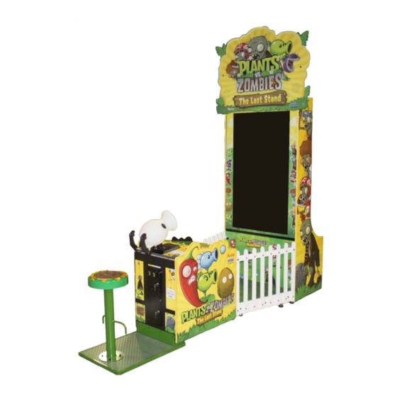
GAME DISCRIPTION AND SOFTWARE Game Overview The smash hit PC and mobile tower defense game has come to the arcade in an all new 3D World! Plants vs. Zombies™ The Last Stand (PvZ: TLS) puts the player at the control of a cabinet mounted Peashooter that is used to zap advancing waves of zombies with peas. - Page 25 Name Entry Once a credit has been inserted (or the SERVICE BUTTON has been pressed to give a service credit) the player will be asked to enter their initials. The player can do this by using the crosshair on screen and pulling the trigger on the Peashooter. If the player fails to enter their initials in the allotted time, or enters a forbidden combination they will be assigned ‘PLA’.
- Page 26 Peashooter. Unlock codes are distributed in various ways, including playing PvZ: TLS and registering a high score on the Sega Scores website. For more information please visit www.segascores.com or www.segaarcade.com.
- Page 27 This details the score achieved, Zombies defeated and the tickets won. Also the player has the chance to *upload their score on the Sega Scores website and see their ranking in the world. www.segascores.com *mobile phone/tablet with QR code reader and data connection/Wi-Fi required.
- Page 28 The last screen before returning to attract is the High Score Table. This will show how well the player performed against other players. Please note that the HST is specific to each cabinet and is not linked to the Sega Scores website.
-
Page 29: Test Mode
TEST MODE 6-1 TEST MODE TEST MENU Press the TEST button to open the TEST MENU. The following options are available from the Test Menu. Use the SERVICE button to move the cursor to the desired test item. Press the TEST button to enter the selected item. SYSTEM INFORMATION General Information on Software. -
Page 30: System Information
Version number of currently installed game IO BOARD VERSION Version number of IO board in use SECURITY KEY Type of security key in use MACHINE ID Unique number of the cabinet used to register on Sega Scores website (please visit www.segascores.com for instructions) - Page 31 INPUT TEST Select ‘Input Test’ from the Test Menu screen to display the Input Test menu. This screen is used to test the system inputs such as the Peashooter triggers, ticket notch and coin input. To implement the test, operate each device listed and check the results on screen. When activated and detected by the system the result on screen will be ON.
- Page 32 OUTPUT TEST Select ‘Output Test’ from the Game Test Mode to display the Output Test Menu. This test is used to check all configured outputs from the IO board. Use the SERVICE button to move the cursor to the desired test item. Press the TEST button to test the selected item.
- Page 33 COIN TEST Select ‘COIN TEST’ from the Test Menu screen to display the Coin Test screen. COIN COUNT Coin Count value from IO board (cannot reset) CREDITS Total number of Coin credits added to the system SERVICE CREDITS Total number of Service Credits added to the system FREEPLAY ON –...
- Page 34 SOUND TEST Select ‘SOUND TEST’ from the Test Mode to display the Sound Test screen. This test is used to test the function of the speakers and set audio levels for the Game. AUDIO IN ATTRACT ON – sound will be played in Attract mode OFF –...
- Page 35 SCREEN TEST Select ‘SCREEN TEST’ from the Test Mode to display the Screen Test screen. This test is used to display various test patterns for the display screen. COLOUR BARS Displays vertical colour bars for colour balance correction BRIGHTNESS Displays graduated greyscale for brightness adjustment GRID ALIGNMENT Displays grid for screen size and alignment...
- Page 36 CONTROLLER TEST Select ‘CONTROLLER TEST’ from the Test Mode to display the Controller Test screen. This test is used to calibrate the x and y coordinates of the Peashooter gun, this is to ensure reliable and accurate game play. The calibration procedure requires you to MOVE the Peashooter gun as instructed on screen and then to press the TRIGGER.
-
Page 37: Bookkeeping
6-3 BOOKKEEPING BOOKKEEPING Select ‘BOOKKEEPING’ from the Test Mode to display the Bookkeeping Test screen. This test is used to review statistical data from the system. It consists of 4 screens of data. BOOKKEEPING PAGE 1 This page displays an overview of the coins and credits data. TOTAL PLAYS The total numbers of games played AVERAGE GAME TIME... - Page 38 CLEAR HI SCORES Selecting this will delete ALL Hi Score data. WARNING – ONCE DELETED THIS INFORMATION CAN NOT BE RESTORED NEXT PAGE This will take you to Page 2 of Bookkeeping EXIT Return to the main Test Menu screen. BOOKKEEPING PAGE 2 This page displays ticket pay out ranges and total Super Bonus wins.
- Page 39 BOOKKEEPING PAGE 3 This page displays breakdown of the games on individual days. This is a cumulative total from the last point in time that the Bookkeeping was cleared. PLAY ON SUNDAY Total games played on a Sunday PLAY ON MONDAY Total games played on a Monday PLAY ON TUESDAY Total games played on a Tuesday...
- Page 40 BOOKKEEPING PAGE 4 This page displays a breakdown of the games into hourly periods. This is a cumulative total from the last point in time that the Bookkeeping was cleared. Each hour is logged separately in 24 hour format therefore 00-01 logs games between 12am and 1am 00-02 logs games between 1am and 2am.
-
Page 41: Setting The Clock
6-4 SETTING THE CLOCK CLOCK SETTING Select ‘CLOCK SETTING’ from the Test Menu screen to enter the Clock Setting screen. This screen is used to set the time and date of the system. CURRENT TIME Shows the current time. Displayed in 24 hour clock format HH:MM:SS CURRENT DATE Shows the current date. -
Page 42: Game Settings
6-5 GAME SETTINGS GAME SETTINGS Select ‘GAME SETTINGS’ from the Test Menu screen to enter the Game Settings screen. This test is used to change the language of the in game text, ticket payout type and difficulty. NOTE TEST MENU text only displays in ENGLISH. The following option is available from the Game Settings screen LANGUAGE Options available... - Page 43 TICKET PAYOUT SETTINGS Select ‘TICKET PAYOUT SETTINGS’ from the Test Menu screen to enter the Ticket Payout Settings screen. This test is used to change the percentage payout settings for the game, as well as enabling/disabling Mercy Tickets. TICKETS PER GAME This value will automatically change based on the settings assigned below The following options are available from the Game Settings screen...
- Page 44 100, 200, 300, 400, 500, 600, 700, 800, 900, 1000 PAYOUT IN FREEPLAY Turn ON/OFF the option to pay tickets out in Freeplay. Default setting is OFF EXIT Exit Ticket Payout Settings saving the changes you have made.
-
Page 45: Controller Unit
CONTROLLER UNIT(S), SWITCHES AND BUTTONS • When working with the product, be sure to turn the power off. Working with the power on may cause an electric shock or short circuit. • Be careful not to damage the wires. Damaged wires may cause an electric shock, short circuit or present a risk of •... -
Page 46: Controller Unit
7-1 REMOVING THE CONTROLLER Be sure to disconnect the power from the machine before performing any work. Failure to remove the power may result in electric shock or component damage. Turn off the power. Remove the 2x screws from the small trap plate located at the front of the Gun base. - Page 47 Remove the 4 screws which secure the Control Panel to the cabinet. REMOVE FIXINGS REMOVE FIXINGS Carefully slide out the Controller Base and Control Panel in opposite directions as illustrated. Remove the 4x M8 Hex Bolts located at the base of the Controller. Take care in disconnecting the Controller Harness and remove the controler.
-
Page 48: Adjusting Volume Pot
Be sure to perform volume's move value setting in the INPUT ASSIGNMENTS in the Game Test Mode after replacing or adjusting the Volume. 7-2 ADJUSTING/REPLACING THE VOLUME POT ADJUSTMENT PROCEDURE LOOSEN FIXINGS H VOLUME BKT V VOLUME BKT Apply this procedure to both Horizontal and Vertical Volume Pots. Loosen the 2 screws that secure the VR Bracket and move the VR Bracket to adjust the angle and condition of the gear alignment. - Page 49 REPLACEMENT PROCEDURE This procedure requires the following tools: Phillips screwdriver for the M4 screws, 1.5 mm hexagonal wrench, 11- 12 mm monkey wrench, nipper, cutter, wire stripper, soldering iron, industrial dryer and heat-shrinkable tube. Remove the connectors. Remove the 2 screws securing the VR Bracket and remove the entire Bracket and V.R. (See previous instruction) Loosen the 1 hexagon socket screws on the Gear Holder and remove the Gear Holder.
- Page 50 The wire connected to the volume pot will be reused. Use a tool such as a pair of snips or cutters to remove the old heatshrink tubes which cover the contacts. Use a soldering iron to melt the solder and seperated the wires from the old volume pot. Be very careful when using a soldering iron.
-
Page 51: Greasing
7-3 GREASING • Be sure to use the designated grease. Using undesignated grease can cause parts damage. • Do not apply grease to locations other than as Doing so may create a risk of operational problems and deterioration of parts. •... -
Page 52: Lcd/Plasma Display
LCD DISPLAY (VGA) 8-1 SAFETY PRECAUTIONS WHEN HANDLING THE MONITOR Responding to breakdown or abnormality ● If smoke or a strange odor appears, immediately unplug the power cable from the power source. Continuing to use the product may cause a or an electric shock. -
Page 53: Cleaning Screen
8-2 CLEANING THE SCREEN SURFACE ● Use a soft, dry cloth to wipe away dirt. Do not use materials such a coarse mesh gauze. ● Alcohol (ethanol) is the recommended solvent for removing dirt. When using a agent, follow the precautions below. Dilute neutral cleaning agents for home use with water. -
Page 54: Coin Handling
COIN HANDLING Handling the Coin Jam If the coin is not rejected when the REJECT button is pressed, open the coin chute door and open the selector gate. After removing the jammed coin, put a normal coin in and check to see that the selector correctly functions. 9-1 CLEANING THE COIN SELECTOR ●... - Page 55 CLEANING THE COIN SELECTOR (MECHANICAL). Remove and clean smears by using a soft cloth dipped in water or diluted chemical detergent and then squeezed dry. Remove the CRADLE.. When removing the retaining ring (E ring) be very careful so as not to bend the rotary shaft.
- Page 56 CLEANING THE COIN SELECTOR (SR3) <continued> Remove and clean smears by using a damp soft cloth dipped in water. DO NOT use any diluted chemical detergent or cleansing agent as this will impair the workings of the component. GATE Open the reject gate to gain access to the rundown path.
-
Page 57: Fault Finding
9-2 FAULT FINDING Fault Finding The following information is presented for customers’ guidance in rectifying a fault but does not cover all possible causes. All acceptors with electronic faults should be returned to an approved service centre for repair. SYMPTOM INVESTIGATE POSSIBLE CAUSE Poor Contact... -
Page 58: Periodic Inspection
PERIODIC INSPECTION The items listed below require periodic check and maintenance to retain the performance of this machine and to ensure safe business operation. When handling the controller, the player will be in direct contact with it. In order to always allow the player to enjoy the game, be sure to clean it regularly. - Page 59 Cleaning the Cabinet Surfaces When the cabinet surfaces are badly soiled, remove stains with a soft cloth dipped in water or diluted (with water) etc. other than ethyl alcohol, or abrasives, bleaching agent and chemical dustcloth. Some general-purpose household, kitchen and furniture cleaning products may contain strong solvents that degrade plastic components, coatings, and print.
-
Page 60: Game Board
GAME BOARD ● When working with the product, be sure to turn the power off. Working with the power on may cause an electric shock or short circuit. ● Be careful not to damage the wires. Damaged wires may cause an electric shock, short circuit or present a risk of ●... -
Page 61: Gameboard Location And Removal
11-1 GAME BOARD - LOCATION & REMOVAL ● When returning the game board after making repairs or replacements, make sure that there are no errors in the connection of connectors. Erroneous connections can lead to electrical shock, short circuits or ●... - Page 62 The GAME BD is mounted on a wooden Base. To remove the GAME BD, disconnect ALL connections to the ASSY GAME BD from within the cabinet. GAME BOARD Slide Out Not Used CONNECTIONS VGA (Video Out) IEC Inlet ON/OFF Switch Audio Not Used Not Used...
-
Page 64: Art Related Parts
DESIGN-RELATED PARTS For the warning display stickers, refer to Section 1. - Page 65 Part Part # Part Name PVG-0502 Billboard Rear PVG-0503 Billboard Name Plate PVG-0504 Billboard Sub Name Plate PVG-1063 Monitor Cabinet Left PVG-1064 Monitor Cabinet Right PVG-1065 Sticker Gun Cabinet Left PVG-1066 Sticker Gun Cabinet Right PVG-1074-A Sticker Gun Rear(How to Play) PV-1074-B Sticker Gun Left(Crazy Dave) PV-1074-C...
-
Page 66: Part Description
PARTS LIST FIGURE 1... - Page 67 FIGURE 1 Part Part # Part Name PVG-0502 Billboard Rear PVG-0503 Billboard Name Plate PVG-0504 Billboard Sub Name Plate PVG-1063 Monitor Cabinet Left PVG-1064 Monitor Cabinet Right PVG-1065 Sticker Gun Cabinet Left PVG-1066 Sticker Gun Cabinet Right PVG-1074-A Sticker Gun Rear(How to Play) PV-1074-B Sticker Gun Left(Crazy Dave) PV-1074-C...
- Page 68 PARTS LIST cont. Gun Mech parts FIGURE 2...
- Page 69 FIGURE 2 Part Part # Part Name 601-11815 Dual Handled Welded Painted F/Sega Analog Gun Screw, #8-32 x3/8 HEX Head 601-11826 Bracket Coil Mounting F/Sega Analog Gun 601-11827 Coil with Tubing 601-11828 Plunger F/Solenoid 601-11829 Bumper Solenoid Stop Screw #8-32x3/8 HEX Washer Head MS wiht SEMS...
- Page 70 FIGURE 3...
- Page 71 FIGURE 3 Part Part # Part Name Bottom & Base Brkt SubAssy with Bumper Gun Assy Nut, KEPS 8-32 Bracket Pot MTG Horizontal Set Screw 6-32 x 3/16 Cup Point Shaft 5/8 Diameter Bracket Pot MTG Vertical Lockwasher #10 External Zinc Plated Nut HEX 10-32 Jame Nylock Zinc Plated 601-11839 Gear Segment W/Hub...
- Page 72 PARTS LIST cont. Computers and Boards FIGURE 4...
- Page 73 FIGURE 4 Part Part # Part Name 838-8001-UK Power Supply 400-065-0512-01 Power Supply 400-075-012-01 Sound Amp 838-0012UK Solenoid Driver 838-0005UK I/O Board RD-4500UK Main CPU 838-0015UK Ticket Vend Board...
-
Page 74: Wiring Diagrams
SCHEMATIC DIAGRAM WIRING DIAGRAMS 60" ... - Page 75 SCHEMATIC DIAGRAM WIRING DIAGRAMS...
- Page 78 PRINTING Sega Amusements Europe Limited. 42 Barwell Business Park, Leatherhead Road, Chessington, Surrey, KT9 2NY. United Kingdom. Telephone: +44 (0) 208 391 8090 Facsimile: +44 (0) 208 391 8099 email: mailbox@sega.co.uk Web: http://www.segaarcade.com Play It! Amusements, inc. 252 Beinoris Drive, Wood Dale, IL. 60191, USA...
Need help?
Do you have a question about the Giant Plants vs Zombies The Last Stand and is the answer not in the manual?
Questions and answers