
Related Manuals for Bentone B 10 E R


Summary of Contents for Bentone B 10 E R
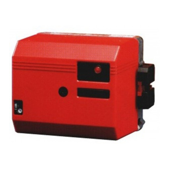
- Page 1 178 013 03-2 2016-05-26 Providing sustainable energy solutions worldwide Installation- and maintenance instruction B 10 E R...
- Page 3 DESCRIPTION Components 1. Scale, nozzle assembly 9. Ignition cables 17. Indicating lamp, preheater 2. Nozzle assembly adjustment 10. Ignition transformer 18. Fan wheel 3. Photocell 11. Electrical connection 19. Air regulation 4. Preheater 12. Control box 20. Scale, air regulation 5.
-
Page 4: Technical Data
TECHNICAL DATA Flange A ø89,5 Dimensions 130-150 Flange B ø89,5 130-150 Flange C ø89,5 Burner tube Length of Flange A Flange B Flange C burner tube Measure B Measure B Measure B 130-150 Output range and nozzles recommended Burner tube Oil capacity Capacity Recommended Recommended... -
Page 5: General Instructions
GENERAL INSTRUCTIONS General rules Measures to raise the temperature: Air adjustment Insulate the chimney in cold attics The installation of an oil burner On all burners the air adjustment can Install a tube in the chimney should be carried out in accordance be made with or without the cover itted. Final ine adjustment must be Install a draught regulator (dilutes the... - Page 6 MAINTENANCE OF OIL BURNER Warning: Before doing any service switch off power at the main switch and cut off the oil supply. Service of burner head (alt. a) 1. Remove the cover. 2. Withdraw the photo resistor. 3. Loosen the connecting pipe. 4. Loosen two ixing screws of the nozzle assembly cover.
-
Page 7: Electric Equipment
ELECTRIC EQUIPMENT OIL BURNER CONTROL: LOA21... / LOA24... List of components Wiring diagram A1 Oil burner control (1)(2) A2 Twin thermostat F1 Fuse, max. 10A H1 Alarm lamp H2 Signal lamp (optional) M1 Burner motor P1 Time meter (optional) R1 Photoresistor S3 Main switch T1 Ignition transformer Y1 Solenoid valve X1 Plug-in contact, burner... - Page 8 ELECTRIC EQUIPMENT Function 1. Switch on operating switch and twin thermostat The burner motor starts, an ignition spark is formed, the prepurge goes on till the prepurge period expires and the solenoid valve opens (2). 2. Solenoid valve opens Oil mist is formed and ignited. The photocell indicates a lame. (1) The ignition spark goes out 15 s. after lame indication (LOA24.171...). (2) The ignition spark goes out 2 s. after lame indication when the ignition transformer is connected to terminal 7 (LOA24.173...). 3.
- Page 9 INSTRUCTIONS PUMP TYPE DANFOSS BFP41 Technical data Viscosity range: 1,3-12,0 mm Pressure range: 7-15 bar Oil temperature: -10 to +70°C Components 1 Nozzle port G1/8" 2. Pressure gauge port 3. Pressure adjustment, 4mm allen key 4. Cartridge ilter 5. Vacuum gauge port G1/8" 6. Return line G¼" 7. Suction line G¼" 8. Return plug Suction line tables The suction line tables consist of theoretically calculated values where...
- Page 10 INSTRUCTIONS PUMP TYPE DANFOSS BFP41 Function Danfoss BFP41 When the oil pump is started, oil is drawn from the suction connection (S) through the ilter (H) to the suction side of the gear wheel (C). The gear wheel then pumps oil to the pressure side and the oil is put under pressure. The pressure is controlled and kept constant at the set value by the ) with the...
-
Page 11: Nozzle Table
NOZZLE TABLE Pump pressure bar kg/h Mcal/h kg/h Mcal/h kg/h Mcal/h kg/h Mcal/h 0,40 1,33 1,41 1,49 1,56 0,50 1,66 1,76 1,86 1,95 0,60 2,00 2,12 2,23 2,34 0,65 2,16 2,29 2,42 2,54 0,75 2,49 2,65 2,79 2,93 0,85 2,83 3,00 3,16 3,32... - Page 12 NOZZLE TABLE Pump pressure bar kg/h Mcal/h kg/h Mcal/h kg/h Mcal/h kg/h Mcal/h 0,40 1,63 1,70 1,76 1,82 0,50 2,04 2,12 2,20 2,28 0,60 2,45 2,55 2,64 2,73 0,65 2,65 2,75 2,86 2,96 0,75 3,08 3,18 3,30 3,42 0,85 3,47 3,61 3,74 3,87...
-
Page 13: Fault Location
FAULT LOCATION Burner fails to start Situation Possible causes Remedies Motor runs Flame instability Burner pre-purges Check nozzle to burner head dimension Incorrect head settings and electrode position Low oil pressure Check oil pressure Flame occurs Excess air Adjust air damper Burner locks out Check that photocell is clean and unobstructed... - Page 14 CONNECTION OF PRESSURE SWITCH TO THE COMBUSTION CHAMBER OF THE BOILER OR THE FLUE - Connect a steel pipe ø 6/4 to the - The pressure switch shall shut off - The switch-off point of the combustion chamber or the lue the burner if the pressure in the pressure switch is adjusted by combus-tion chamber (chimney) of the boiler.
- Page 15 Burner control S20 Pressure switch Terminal strip Ionisation electrode Photoresistor 2(2) 171 905 04 08-01...
- Page 16 OIL BURNERS MAINTENANCE INSTRUCTIONS General information If the burner starts but does not ignite Keep the boiler room clean. Ensure that the boiler Make an attempt to start the burner. room has permanent fresh air intake. Switch off before Never make close repeated start attempts. dismantling the oil burner.
- Page 20 170 080 06 10-01...
Need help?
Do you have a question about the B 10 E R and is the answer not in the manual?
Questions and answers