Table of Contents
Advertisement
Quick Links
Advertisement
Table of Contents

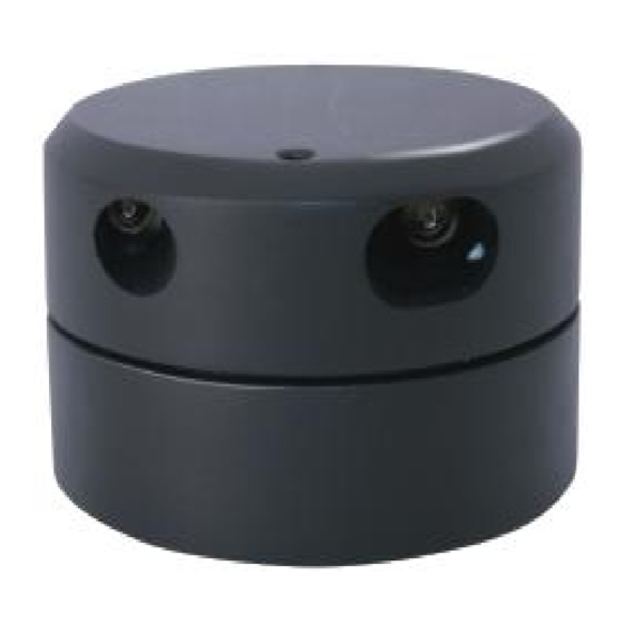
Summary of Contents for EAI YDLIDAR X2
- Page 1 USER MANUAL www.ydlidar.com Copyright 2015-2020 YDLIDAR 1/11...
-
Page 2: Table Of Contents
CONTENTS DEVELOPMENT KIT........................... 3 YDLIDAR X2/X4..........................3 YDLIDAR G2/G4/G6........................3 WINDOWS USAGE GUIDE........................4 Device connection........................4 Driver Installation........................5 LINUX ROS OPERATION........................7 Device connection........................7 YDLidar-SDK Installation......................7 ROS Driver Installation........................ 8 RVIZ installation...........................8 Run ROS Package......................... 9 RVIZ results..........................9 Modify Angle Problem........................ -
Page 3: Development Kit
DEVELOPMENT KIT The development kit of YDLIDAR is an accessory tool provided for performance evaluation and early development of the sensors. YDLIDAR X2/X4 USB Adapter USB Micro cable YDLIDAR X2/X4 PH2.0-8P board YDLIDAR G2/G4/G6 G2/G4/G6 Lidar USB Type-C cable USB Adapter board www.ydlidar.com... -
Page 4: Windows Usage Guide
At this time, auxiliary power supply can be used. WINDOWS USAGE GUIDE Device connection When evaluating and developing Lidar under windows, you need to interconnect Lidar and PC. The specific process is as follows: FIG 1 YDLIDAR X2/X4 www.ydlidar.com Copyright 2015-2020 YDLIDAR 4/11... -
Page 5: Driver Installation
FIG 2 YDLIDAR G2/G4/G6 Connect the adapter board and Lidar first, and then connect the USB cable to the USB port on the adapter board and the PC. Note that the USB cable is connected to the USB adapter's USB_DATA. After the Lidar is powered on, it is in idle mode and the motor does not rotate. - Page 6 After extracting the driver package, run the CP2102's Windows driver installation file (exe file under CP210x_VCP_Windows). Please select the 32-bit version (x86) or 64-bit version (x64) installation program according to the version of the windows operating system. FIG 4 YDLIDAR DRIVER VERSION SELECTION Double-click the exe file and follow the prompts to install it: FIG 5 YDLIDAR DRIVER INSTALLATION I After the installation is complete, you can right-click on My Computer and select Properties.
-
Page 7: Linux Ros Operation
Note : Users can also choose Type-C on G2/G4/G6 to get started quickly. Connect the PC and G2/G4/G6 directly with Type-C data cable and download the vcp serial port driver of G6 on the www.ydlidar.com. After that, start the PCV to scan the map and observe the data. LINUX ROS OPERATION This article only uses Ubuntu 16.04, Kinetic version ROS as an example. -
Page 8: Ros Driver Installation
ROS Driver Installation Before doing the following, make sure that the Kinetic version ROS environment is installed correctly. 1. Use the command to create the ydlidar_ws workspace and copy the ROS driver package ydlidar_ros_driver in the YDLIDAR package to the ydlidar_ws/src directory. Switch to the ydlidar_ws workspace and compile again. -
Page 9: Run Ros Package
Run ROS Package Run the corresponding launch file according to the lidar model, The command format is: $roslaunch ydlidar_ros_driver [launch file] Examples of use are as follows: X2 Lidar $ roslaunch ydlidar_ros_driver X2.launch X4 Lidar $ roslaunch ydlidar_ros_driver X4.launch G2 Lidar $ roslaunch ydlidar_ros_driver G2.launch G4/G5 Lidar $ roslaunch ydlidar_ros_driver lidar.launch... - Page 10 To modify the display range, you need to modify the configuration parameters in the launch file. The specific operation is as follows: 1. Go to launch directory and use vim to edit launch file of the corresponding Lidar model(take X4 as an example). The contents are as shown in the figure: $ roscd ydlidar_ros_driver/launch $ vim X4.launch FIG 9 YDLIDAR.LAUNCH FILE...
-
Page 11: Use Caution
USE CAUTION Temperature When the working environment temperature of YDLIDAR is too high or too low, it will affect the accuracy of the distance measuring system. It may also damage the structure of the scanning system and reduce the life of the YD lidar. Avoid use in high temperature (>40 degrees Celsius) and low temperature (<0 degrees Celsius) conditions.
Need help?
Do you have a question about the YDLIDAR X2 and is the answer not in the manual?
Questions and answers