Advertisement
Quick Links
INSTALLATION OF COMPONENTS:
Identify all the parts supplied and those in the accessories bags.
Intake Unit: insert onto one side of the adjustable intake tube (Q) the strainer (G) and the
intake tube (R) on the other side. Mount the Elbow with integrated flow control device (U)
complete with screw-nut (A) onto the other side of the intake tube (R). Mount the 2 clips (S)
to the 2 suction cups (T).
Outlet Unit: insert the curved adapter (V) onto the elbow with integrated flow-control device
(U) and fix it with the hose adapters (A). Insert then either the spray-bar with cap (X) or the
flow diverter (Y) according to your needs. Mount the 2 clips (S) to the 2 suction cups (T) and
adjust the distance accordingly from the tank wall.
Finally mount the 2 hose adapters (A) on the spigots IN-OUT in the hose connecting
device (B).
ASSEMBLING AND STARTING THE FILTER Photo 1 - Insert the rubber feet in their
locations of the filter media container
Photo 2 - Open the filter head by releasing the clips from above and by pulling them
outward. The filter head will disengage from its seat.
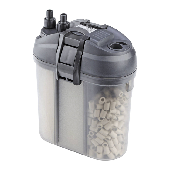
Photo 3 - Rinse the ceramic media under running water and fill the empty bio media
chamber (I). For proper re-circulation make sure that the ceramic media are placed on the
side of the cap (W) of filter head before closing the filter head as indicated by the arrow on
Photo 3.
The air tube in the impeller chamber must be oriented toward the upper side of the filter as
shown as in Photo 3.
Photo 4 - To close the filter, position the clips correctly under the locking notch of the media
container. Push the clips inward until they lock with a clear click-on sound into their seats.
Photo 5 - Unlock the cap (W) and fill up completely with water. Close the cap until the
locking device clicks to lock. To carry the filter, use the folding handle on the pump head.
Only On Models 521-522.
Photo 6 - Thoroughly clean the aquarium wall before fixing the assembled intake and outlet
units in the desired position. Adjust the distance of the clips from the tank wall according to
the size of your aquarium by inserting the units either onto the first or second eyelet in each
clip (S). Adjust the length of the intake tube by moving the intake tube with strainer (Q)
according to the depth of your tank. Only On Models 521-522. Then push the hoses onto
the spigots of the intake and outlet and lock them with the screw-nuts.
Photo 7 - Insert the hoses in the hose connecting device (B). Make sure they are properly
inserted in the in- (IN) and outlet (OUT). Lock them with the screw nuts. If necessary it is
recommended to adjust the flow of the filter by rotating the flow control device of the intake
unit toward min or max (orange flow control).
Photo 8 - Plug the filter to mains.
SAFETY WARNINGS:
• Check that the voltage shown on the label of the unit corresponds to the voltage of the
mains supply.
• Connect the unit to a power supply with a Residual Current Device (RCD) with sensitivity
of 30mA.
• Always disconnect all electrical appliances from the mains before placing your hands in
the water.
• The power supply lead of this appliance cannot be replaced or repaired.
• Should the lead become damaged the appliance must be discarded.
• This unit is intended exclusively for indoor use only
• This unit must not be used in swimming pools or bathrooms.
• This appliance has been designed for use in fluids up to 35°C.
• Keep these instructions for future reference.
Very important notice!
This equipment is not intended for use by per- sons (including children) with limited
physical, sensory or mental abilities or for persons with no experience or knowledge
unless they are supervised by a person responsible for safety or unless they have received
from such a person instructions on how to use this equipment.
Children should be supervised to ensure that they do not play with the equipment.
MAINTENANCE
Before any maintenance, media replacement, cleaning operation, etc. it is recommended to
move the complete unit to a sink or similar place and follow these instructions carefully:
Always disconnect all electrical appliances from mains before placing your hands in water.
Photo 9 - Turn the hose connecting device (B) in the UNLOCK position and remove it from
its place (Photo 9). Open the filter head by releasing the clips and pulling them outward
until the O-Ring (Z) on the head comes loose (see Photo 2). Remove the filter head from
the media container (Photo 3).
Photo 10 - Take off the strainer (G) of the impeller chamber (F) by pressing the locking
notch inside the head near the cap (W) as shown as in Photo 10. Only On Models 521-522.
Photo 11 - Take off the impeller unit (D). To remove the bearings of the impeller chamber
insert the pin of the impeller chamber in its hole. Carefully rinse the rotor, bearings, impeller
chamber, strainer and the impeller seat.
The filter foams should only be rinsed in aquarium water to avoid loss of beneficial bacteria.
Reassemble all components paying special care to the right positioning of the air tube (E)
that must be oriented towards the upper side of the filter (Photo 3).
Attention!
A special internal device discharges the air that remains in the upper part of the filter head.
The length of this operation depends on the quantity of air inside and may take a few
minutes. The noise will disappear as soon as the system has discharged the air.
The filter will be correctly closed only after positioning the filter head onto its seat on the
media container and after the clips have properly clicked on to the cover (Photo 4).
Photo 12 - Avoid kinking of hoses. (Photo 12)
Disposal: (in accordance with RL2002/96/EC) The Product must not be added to normal
household waste. It must be disposed of properly.
Advertisement

Related Manuals for Eden 511


Summary of Contents for Eden 511
- Page 1 of 30mA. • Always disconnect all electrical appliances from the mains before placing your hands in the water. • The power supply lead of this appliance cannot be replaced or repaired. • Should the lead become damaged the appliance must be discarded. •...
- Page 2 WARRANTY With this product we offer you a guarantee of 36 months from the date of purchase on materials and manufacturing faults. This unit has been manufactured according to the IEC EN 60 335-2-41, EN 60 335-2-55 Safety Standards, using high quality materials and the most accurate manufacturing processes to grant the highest satisfaction and long lasting.
Need help?
Do you have a question about the 511 and is the answer not in the manual?
Questions and answers