Table of Contents
Advertisement
Quick Links
Advertisement
Table of Contents
Troubleshooting

Related Manuals for Vaisala PWD22/52


Summary of Contents for Vaisala PWD22/52
- Page 1 USER'S GUIDE Vaisala Present Weather Detector PWD22/52 M210543EN-E...
- Page 2 English versions are applicable, not the translations. The contents of this manual are subject to change without prior notice. This manual does not create any legally binding obligations for Vaisala towards customers or end users. All legally binding obligations and agreements are included exclusively in the applicable supply contract or the General Conditions of Sale and General Conditions of Service of Vaisala.
-
Page 3: Table Of Contents
Regulatory Compliances ............14 Trademarks ................14 License Agreement ..............14 Warranty.................. 14 CHAPTER 2 PRODUCT OVERVIEW................15 Introduction to Vaisala Present Weather Detector PWD22/52 ................15 Hardware Structure ..............16 Using PWD22/52..............16 Product Nomenclature............17 CHAPTER 3 FUNCTIONAL DESCRIPTION..............19 Optical Measurements ............ - Page 4 USER'S GUIDE____________________________________________________________________ CHAPTER 4 INSTALLATION....................29 Selecting Location..............29 Grounding and Lightning Protection ........31 Equipment Grounding ............31 Internal Grounding of PWD22/52 ........31 Grounding the Remote Units and the Communication Cable ...................31 Installation Procedure............32 Unpacking Instructions ............32 Unpacking Procedure.............32 Storage ................32 Mounting................33 Connections ................34 Connecting Cables ..............34...
- Page 5 Common Problems ..............93 Message Indicating Warning or Alarm ........ 93 Message Missing ..............93 Message Exists but Visibility Value Does Not..... 94 Visibility Value is Continuously Too Good ......95 Visibility Constantly Too Low ..........95 VAISALA ________________________________________________________________________ 3...
- Page 6 USER'S GUIDE____________________________________________________________________ PWD22/52 Reports Precipitation When There Is None ..96 PWD22/52 Reports Frozen Precipitation during Rain..96 PWD22/52 Electrical Troubleshooting.........97 Technical Support ..............98 Product Returns..............98 CHAPTER 8 TECHNICAL DATA ..................99 Specifications .................99 Mechanical Specifications ...........99 Electrical Specifications.............100 Optical Specifications ............100 Visibility Measurement Specifications .......101 Weather Sensing Specifications........101...
- Page 7 LED Indicators on the PWC22/52 Board........26 Figure 7 Recommended Location of PWD22/52 Sensor....... 30 Figure 8 Installing PWD22/52 to the Support Arm ......... 33 Figure 9 Installing the Subassembly to the Mast with the Vaisala Clamp Assembly ..............33 Figure 10 Testing the Connector ..............
- Page 8 USER'S GUIDE____________________________________________________________________ This page intentionally left blank. 6 ___________________________________________________________________ M210543EN-E...
- Page 9 Values from STA message for Internal Monitoring ....103 Table 25 Internal Weather Types and Supported NWS Codes .... 111 Table 26 WMO SYNOP Codes (Table 4680, W ) Used by PWD22/52 ................111 Table 27 WMO METAR Codes (Table 4678) Used by PWD22/52..112 VAISALA ________________________________________________________________________ 7...
- Page 10 USER'S GUIDE____________________________________________________________________ This page intentionally left blank. 8 ___________________________________________________________________ M210543EN-E...
-
Page 11: Chapter 1 General Information
- Chapter 7, Troubleshooting, describes common problems, their probable causes and remedies, and provides contact information for technical support. - Chapter 8, Technical Data, provides the technical data of PWD22/52. - Appendix A includes Values for Internal Monitoring. - Appendix B includes Jumper Settings. -
Page 12: Version Information
M210543EN-D Previous version. Related Manuals Table 2 Related Manuals Manual Code Manual Name M210542EN Vaisala Present Weather Detector PWD12, User's Guide M210541EN Vaisala Visibility Sensor PWD10/20/50, User's Guide Documentation Conventions Throughout the manual, important safety considerations are highlighted as follows: Warning alerts you to a serious hazard. -
Page 13: Safety
Vaisala Present Weather Detector PWD22/52 delivered to you has been tested for safety and approved as shipped from the factory. Note the following precautions: WARNING The chassis of the PWD22/52 must be connected to a good electrical earth. ® WARNING Do not touch the surface of the RAINCAP Rain sensor plate. - Page 14 USER'S GUIDE____________________________________________________________________ CAUTION Tighten the connector properly. The cable connector must not swing in relation to the fixed connector. CAUTION Servicing the equipment must be performed by qualified personnel. RADIO FREQUENCY INTERFERENCE STATEMENT (USA) The United States Federal Communications Commission (in 47 CFR 15.838) has specified that the following notice must be brought to the attention of users of this kind of a product in the USA: Federal communications commission radio frequency interference...
-
Page 15: Esd Protection
ESD Protection Electrostatic Discharge (ESD) can cause immediate or latent damage to electronic circuits. Vaisala products are adequately protected against ESD for their intended use. However, it is possible to damage the product by delivering electrostatic discharges when touching, removing, or inserting any objects inside the equipment housing. -
Page 16: Regulatory Compliances
United States and/or other countries. License Agreement All rights to any software are held by Vaisala or third parties. The customer is allowed to use the software only to the extent that is provided by the applicable supply contract or Software License Agreement. -
Page 17: Chapter 2 Product Overview
PWD22/52 is an intelligent, multi-variable sensor for automatic weather observing systems. The sensor combines the functions of a forward scatter visibility meter and a present weather sensor. PWD22/52 can measure the intensity and amount of both liquid and solid precipitation. If the detector is equipped with a background luminance sensor, it can also measure ambient light. -
Page 18: Hardware Structure
USER'S GUIDE____________________________________________________________________ Hardware Structure PWD22/52 is a self-contained instrument that can be fastened to the side of the mast and into a cross arm using the mounting clamps. 0308-002 Figure 1 PWD22/52 Present Weather Detector The following numbers refer to Figure 1 above. -
Page 19: Product Nomenclature
A capacitive detector to sense Rain Sensor water droplets and/or moisture. Two plate in a 90-degree angle towards each other. Table 5 Nomenclature for Options of the Vaisala Present Weather Detector PWD Family Code Common Name Description PWL111 Background Luminance... - Page 20 USER'S GUIDE____________________________________________________________________ This page intentionally left blank. 18 __________________________________________________________________ M210543EN-E...
-
Page 21: Functional Description
CHAPTER 3 FUNCTIONAL DESCRIPTION This chapter describes the functionality of the product. Vaisala Present Weather Detector PWD22/52 is an optical sensor that measures visibility (meteorological optical range, MOR), precipitation intensity, and precipitation type. The detector measures visibility using the principle of forward scatter measurement. Light scatters from particles whose diameter is in the order of magnitude of the wavelength of the light. -
Page 22: Figure 2 Pwd22/52 Block Diagram
Power Serial line Three Relay Controls Measurement Power RS-232 Interface 12-50VDC RS-485 Interface (2 wire) Heater Power (with hood heaters and luminance sensor, 12...50VDC/VAC heater power must be 24VAC or 24VDC) 1008-014 Figure 2 PWD22/52 Block Diagram 20 __________________________________________________________________ M210543EN-E... -
Page 23: Optical Measurements
PWD22/52 has a small sample volume of about 0.1 liters (see Figure 3 above). This allows for independent particles to be measured even at relatively heavy precipitation intensities. -
Page 24: Light Receiver
The capacitance of the elements controls the output frequency of an oscillator. The frequency signal is measured once a second. The frequency is handled in the PWD22/52 internal units. The DRY value is about 800, which is also shown in the Status (STA) message. 22 __________________________________________________________________ M210543EN-E... -
Page 25: Background Luminance Sensor Pwl111 (Optional)
If the relative humidity of the air is more than about 70 %, the surfaces produce a measurable signal even with no precipitation. In PWD22/52 this is used as an estimated humidity measurement. The estimated humidity is used to separate between dust and mist. -
Page 26: Blsc Command
0 or 1. Zero indicates night time and one indicates day time. See the example below: >BLSC 0 Disabling PWL111 The negative scale directs PWD22/52 to skip the background luminance action. See the example below: >BLSC -1 BLCAL Command... -
Page 27: Temperature Sensor
Figure 5 PWL111 Block Diagram Temperature Sensor The primary temperature sensor of PWD22/52 is a Pt100 thermistor attached to the cross arm. The temperature is measured once a minute using a high resolution A/D converter. The sensor cross arm temperature (TS) is used to select the default precipitation type. -
Page 28: Internal Monitoring
USER'S GUIDE____________________________________________________________________ Internal Monitoring Built-in Tests Extensive, built-in tests are included in the PWD22/52 operation. Various voltages are measured and corresponding alarm and warning limits are checked. Optical contamination of both the transmitter and the receiver is continuously monitored by measuring the backscattered light. For this purpose an additional transmitting LED is installed in the receiver. -
Page 29: Memory Tests
Chapter 3 ______________________________________________________ Functional Description Memory Tests After resetting, PWD22/52 tests and clears its SRAM data memory. It indicates an error by the Signal/Offset LED blinking. After 50 blinks PWD22/52 tries to start the program anyway. Usually this causes a watchdog reset, if the SRAM is really faulty. -
Page 30: Monitoring Contamination
USER'S GUIDE____________________________________________________________________ Monitoring Contamination PWD22/52 monitors both transmitter and receiver contamination by measuring the backscattered signal. The CLEAN command is used to set the clean reference values of the backscatter signals. Deviation of the backscatter signal from the clean values is proportional to the contamination on the lenses The alarm and warning limits are given in the configuration session. -
Page 31: Chapter 4 Installation
Locate PWD22/52 in such a way that the measurements will be representative of the surrounding weather conditions. - The ideal site for PWD22/52 has a minimum clearance of 100 m from all large buildings and other constructions that generate heat and obstruct precipitation droplets. Avoid the shade of trees because the trees may cause changes in the microclimate. -
Page 32: Figure 7 Recommended Location Of Pwd22/52 Sensor
Power supply and communication lines must be available. - When siting PWD22/52, consideration must be given to the available power supply and communication lines, as this influences the amount of work and accessories needed, and hence the actual cost of installation. -
Page 33: Grounding And Lightning Protection
Equipment Grounding Equipment grounding protects the electrical modules of PWD22/52 among other things against lightning and prevent radio frequency interference. Equipment grounding for PWD22/52 is done via the weather station grounding cable. The grounding principles are the following: Install the grounding rod as close to the pole mast as possible. That is, minimized the length of the grounding cable. -
Page 34: Installation Procedure
Do not bend the signal cable with less than 2 cm (1 inch) radius, and do not leave it unsupported to lean to the ground or table. Storage Store PWD22/52 in its package in dry conditions, not in the open air. The storage conditions are as follows: - Temperature -40 °C to 70 °C... -
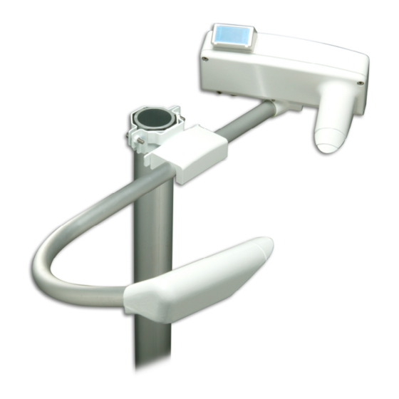
Page 35: Mounting
Chapter 4 _______________________________________________________________ Installation Mounting When installing PWD22/52 with the sensor support arm, proceed as follows: Install PWD22/52 to the support arm. See Figure 8 below. 0308-005 Figure 8 Installing PWD22/52 to the Support Arm 0308-004 Figure 9 Installing the Subassembly to the Mast with the Vaisala Clamp Assembly Or install the subassembly to the mast. -
Page 36: Connections
Tighten the connector properly. The cable connector must not swing in CAUTION relation to the fixed connector. Insulate the unused wires of the PWD22/52 mast cable from each other, for example, by connecting them to void screw terminals in the junction box. -
Page 37: Basic Wiring
Chapter 4 _______________________________________________________________ Installation Basic Wiring The PWD22/52 cable has 16 connection wires. Table 6 Receptable Connector Default Wiring Signal Name PWC15PB PWC- Mast cable Wire Remarks board connector Color Sensor DC Power + X1 - 1 X1 - 4... -
Page 38: Figure 11 Cabling Principle
USER'S GUIDE____________________________________________________________________ 0104-002 Figure 11 Cabling Principle 0309-044 Figure 12 Maintenance Cable 36 __________________________________________________________________ M210543EN-E... -
Page 39: Supplying Power To Pwd22/52
Internal Heaters and Heaters for PWL111 Option The heaters for Background Luminance Sensor PWL111 (optional) are parallel to the PWD22/52 internal heaters (connector X18 on the PWC22/52 board). Both heaters are powered by the PWD operating voltage line and the DC voltage level must be between 12 V and 28 V (24 V recommended). -
Page 40: Pwh111 Hood Heaters
. They use 30 W each, which is 60 W altogether. Communication Options PWD22/52 has one serial line with two interfaces. The two-wire RS-485 is intended to be the standard interface. The PWD22/52 software is designed to allow the RS-232 interface to be used as a service line, when the RS-485 interface is connected to the host computer. -
Page 41: Serial Multipoint Transmission Rs-485
Serial Multipoint Transmission RS-485 The RS-485 transmission standard allows several PWD22/52s to communicate (half duplex) with the host computer using a single twisted pair. For the RS-485 communication connect the PWD22/52 signal wires - BRN RS-485 A (+) - WHT... -
Page 42: Relay Controls
PWD22/52 has three open collector relay controls that are controlled by software using the alarms limits set in the CONF command. The three relay control of PWD22/52 can all be driven by the visibility limits. The third relay control can also be driven by the hardware status. -
Page 43: Figure 14 Relay Connection: Pwd22/52 Supplies
Figure 14 Relay Connection: PWD22/52 Supplies Figure 14 above illustrates external relays connection when relay coils are powered by PWD22/52. Voltage pin VB 12 V and relay controls 1, 2, and 3 are wired by default. NOTE Do not load any of the relay control output pins by more than 35 mA or any Ext Vb voltage output pin by more than 200 mA. -
Page 44: Figure 15 Relay Connection: External Relay Supply
USER'S GUIDE____________________________________________________________________ If external relays require higher coil current, an external power supply must be used for one or two of them. Relay control 3 can be changed to external voltage output of 12 V by jumper X11. Figure 15 below illustrates external relays connecting when relay coils are powered by external voltage. -
Page 45: Relay Command
>RELAY 1 ON Initial Settings Vaisala Present Weather Detector PWD22/52 is typically interfaced to a host computer or a data logger in an automatic weather observing system. After the physical connection has been made, the details of the communication can be configured in the software. Suitable communication settings depend on the implementation of the whole system. -
Page 46: Weather Parameters
USER'S GUIDE____________________________________________________________________ In multipoint communication, where several sensors share the same communication line, PWD22/52 should be used in the polled mode and individual sensors must have distinct identifiers. The commands for changing the default settings are listed in Table 10 below. -
Page 47: Verification
Chapter 4 _______________________________________________________________ Installation Verification Before connecting PWD22/52 to a weather station or other host, a short startup procedure is recommended. Connect a terminal via RS-232 serial line to the sensor. Set the terminal baud rate to 9600 bps and the data frame to contain 7 data bits, 1 stop bit, even parity. - Page 48 USER'S GUIDE____________________________________________________________________ This page intentionally left blank. 46 __________________________________________________________________ M210543EN-E...
-
Page 49: Chapter 5 Operation
Meteorological Organization (WMO) code table 4680 (WaWa, in other words, Present Weather reported from an automatic weather station). PWD22/52 reports present weather also in WMO code table 4678 (METAR) format. In addition, the United States National Weather Service (NWS) abbreviations are available. The NWS list and WMO codes is presented in Appendix C, NWS and WMO Code Tables, on page 111. -
Page 50: Operating Instructions
USER'S GUIDE____________________________________________________________________ Operating Instructions User intervention is not required in the normal operation of PWD22/52. Operator commands are used only in the initial setup and during routine maintenance. Several commands are also available for troubleshooting. When the sensor is installed, the user may need to change some of the default settings. -
Page 51: Entering And Exiting The Command Mode
Entering and Exiting the Command Mode Before any commands can be given to PWD22/52, the communication line in PWD22/52 has to be assigned to the operator. Otherwise, it is assigned to automatic messages or polled communication. The user assigns the command mode with the OPEN command. -
Page 52: Message Types
Message 2 is intended to be the standard present weather message. The length of the STAtus Message 3 depends on the possible alarm and warning states. PWD22/52 adds frame strings to the polled and automatic messages. The content of the frame strings is presented in the following: PW id... -
Page 53: Message 0
- 1=hardware error, 2= hardware warning, 3= backscatter alarm, 4= backscatter warning - 1= visibility alarm 1, 2= visibility alarm 2, 3= visibility alarm 3 The following is an example with frames: □PW 1□00 1839 61 0.3□ 1839 61 1234567890123456789012345678 VAISALA _______________________________________________________________________ 51... -
Page 54: Message 2
USER'S GUIDE____________________________________________________________________ Message 2 Message 2 is intended to be the standard present weather message used in data loggers or display units and set as a default at the factory. Example for PWD22: 1839 1505 R- 61 61 61 0.33 12.16 --- cumulative snow sum,0...999mm... -
Page 55: Messages 5 And 6
These lines are not of fixed length because METAR codes can be combined in many ways. The METAR codes may also be left out but the lines of the message are always terminated by a carriage return and line feed characters. VAISALA _______________________________________________________________________ 53... -
Page 56: Automatic Message Sending
The examples illustrate message 7 when using PWD22. The maximum visibility varies according to the product model. The messages are otherwise identical. Automatic Message Sending In the automatic (CLOSEd) mode PWD22/52 sends the predefined message at selected intervals. Automatic message is selected with the AMES command. AMES Message_number Message_interval... -
Page 57: Message Polling
This format can be used in all cases. Use character 1 as the ID if the ID has not been set but a specific message type is polled. This is to enable the PWD22/52 software to distinguish the ID from the message number. - Page 58 The ID has a two-character field because it can be two characters long. An example of the polled (and automatic) message 0 format is the following: PWD22/52 waits about 100 ms before it transmits the polled message to give the host time to turn the RS-485 line into the receive mode. NOTE...
-
Page 59: Precipitation Sums
Chapter 5 ________________________________________________________________ Operation Precipitation Sums PWD22/52 has no internal clock for automatic resetting of the sum data at certain times. This can be done by the host with the following command: PW id C where ESC (ASCII character 1B hex). -
Page 60: Mes
For example, when choosing the data message number 0, type the following: >MES 0 AMES The AMES command defines the message, which PWD22/52 transmits as the automatic message or as the default polled message. Refer to section Automatic Message Sending on page 54. 58 __________________________________________________________________ M210543EN-E... -
Page 61: Weather Related Commands
PRECIPITATION LIMIT ( 40) WEATHER UPDATE DELAY ( 6) SYNOP HAZE LIMIT ( 10000) METAR HAZE LIMIT ( 5000) RAIN INTENSITY SCALE ( 1.00) HEAVY RAIN LIMIT ( 8) LIGHT RAIN LIMIT ( 2) SNOW LIMIT ( 5.0) VAISALA _______________________________________________________________________ 59... - Page 62 The minimum ratio of optical precipitation intensity to surface sensor (RAINCAP ® precipitation intensity, when precipitation is snow. A typical value for Snow limit is 5. Smaller value directs PWD22/52 to report more wet precipitation as snow. 60 __________________________________________________________________ M210543EN-E...
-
Page 63: Clrs
A typical value for this parameter is 1.0. The precipitation measurement can be calibrated by comparing the PWD22/52 rain amount to measurements made with a suitable reference rain gauge. This comparison should be made after a few rain events with 5 mm or more of total accumulated rain. -
Page 64: System Configuration Commands
1 mA SCALE_1 184.8, SC_0 -1.4 CONF With the CONF command, PWD22/52 asks the system parameters one by one, showing the current value in most cases as the default. The old settings are not changed, if users simply press ENTER as the answer. - Page 65 CONF password N command, where the N character stands for new. After getting the correct password, the system asks for a new password. Press ENTER to remove the password. Otherwise, type a new password. The system response to the CONF command is presented on the next page. VAISALA _______________________________________________________________________ 63...
- Page 66 USER'S GUIDE____________________________________________________________________ Example for PWD22: CONF. PASSWORD (4 CHARS MAX) UPDATE CONFIGURATION PARAMETERS UNIT ID (2 CHAR) () 1 UPDATED SET REFERENCE PARAMETERS OFFSET ( 156.47) Y OFFSET REFERENCE UPDATED MODE UPDATED ALARM LIMIT 1 ( 0) 1500 ALARM LIMIT 1 UPDATED ALARM LIMIT 2 ( 0) 1000 ALARM LIMIT 2 UPDATED...
- Page 67 UPDATE CONFIGURATION PARAMETERS UNIT ID (2 CHAR) ( 1) If the PWD22/52 unit is named by one or two character ID codes, the OPEN and polling commands use it as a parameter. The ID code is also included in the data message heading. ID 1 is used as a default in the message heading, if no other ID is given.
- Page 68 USER'S GUIDE____________________________________________________________________ The alarm limits are also used to control the two (pull down) alarm controls. Control 1 drives, when alarm 1 is on. Control 2 drives, when alarm 2 is on. Control 3 drives, when alarm 3 is on. The controls are usually used to drive external relays.
-
Page 69: Hood Heaters
By default 0, no hood heaters are used. The hood heater option is factory installed and may be used or disabled in the CONF session. All the PWD22/52 heaters are switched ON below 2 °C and off at 5 °C. When using hood heaters, a separate 24 V heating power must be supplied. -
Page 70: Figure 17 Analog Current Output Connection
USER'S GUIDE____________________________________________________________________ 1206-027 Figure 17 Analog Current Output Connection If the PWD cable is so long that the 12 V power output is not adequate, the analog output connection will be done as shown in Figure 18 on page 69. When the external power output is used, one unused wire must be connected between connector X4-8 on the PWD CPU board and the ground of the data collector at the user's end. -
Page 71: Analog Output Modes
Appendix B, PWC22/52 Connectors and Jumper Settings, on page 107. Mode 0 Mode 0 indicates standard linear visibility to the current mode. The maximum visibility must be higher than the minimum visibility as well as the corresponding currents. VAISALA _______________________________________________________________________ 69... -
Page 72: Mode 1
USER'S GUIDE____________________________________________________________________ Mode 1 Mode 1 is the logarithmic mode and it uses ln(visibility) values for the output. The calculation is the following: ⋅ range coeff where Current that flows to analog output current sink. Specified lowest output current value (for example 4 mA). Current range specified range (for example I... -
Page 73: Mode 3
PWD22/52 set two-bit patterns to the DAC circuit and asks for the corresponding measured currents. If the higher current is less than 2 mA, PWD22/52 calculates the current range of 0 ... 1 mA. Otherwise, it calculates the current range of 0 ... 20 mA. - Page 74 USER'S GUIDE____________________________________________________________________ PWD22/52 sets two-bit values to the DAC hardware and asks for the corresponding currents. The currents can be measured with a standard (calibrated) multimeter. PWD22/52 calculates the bits/current scales. Example of the calibration of PWD22 (current sink, 20 mA jumper): Type the following command: >ACAL...
-
Page 75: Maintenance Commands
HARDWARE : The length of the message may vary depending on the options configured in PWD22/52 and whether there are warning messages. An asterisk (*) before a value indicates an exceeded limit. If the Background Luminance Sensor PWL111 is not installed, line BL 26 is edited out. -
Page 76: Cal
USER'S GUIDE____________________________________________________________________ If warnings or errors are detected, one or several of the following texts appear at the end of the message. See Table 15 below and Table 16 below. Table 15 Hardware Error Texts Error Text Description Backscatter High Receiver or transmitter contamination signal has increased more than the ALARM limit given in the configuration allows. -
Page 77: Clean
Chapter 5 ________________________________________________________________ Operation The calibrator signal value is printed on the labels of the glass plates. Typically the signal is close to 500 Hz. PWD22/52 calculates a new scaling factor and stores it in the non-volatile memory (EEPROM). If the PWC22/52 board has been changed and the status message shows... -
Page 78: Chec
DRY ON and WET The DRY ON and WET commands are used to check and adjust the ® operation of the Vaisala RAINCAP Rain Sensor measurement. DRY ON The DRY ON command is used to set the reference level of the dry ®... -
Page 79: Wet
The following is an example of the command: HEAT ON When you want to stop the heater test and quit the test mode, press ESC. NOTE Do not leave the heater testing on in warm conditions for long periods of time. VAISALA _______________________________________________________________________ 77... -
Page 80: Other Commands
USER'S GUIDE____________________________________________________________________ Other Commands TIME The TIME command is used for maintenance purposes. To display the current system time, type the following: TIME The following is an example of the system output: 10:11:12 To set the time, use the following command: TIME hh mm ss where = hours... -
Page 81: Reset
Chapter 5 ________________________________________________________________ Operation RESET The RESET command makes the hardware reset by the watchdog circuitry. The VER command shows the version of the software. VAISALA _______________________________________________________________________ 79... - Page 82 USER'S GUIDE____________________________________________________________________ This page intentionally left blank. 80 __________________________________________________________________ M210543EN-E...
-
Page 83: Chapter 6 Maintenance
This chapter provides information that is needed in basic maintenance of the product. Periodic Maintenance PWD22/52 has been calibrated at the factory. Thus, no initial calibration is required. Periodic maintenance of PWD22/52 includes the following: - Cleaning the transmitter and receiver lenses and hoods. -
Page 84: Cleaning
USER'S GUIDE____________________________________________________________________ Cleaning It is very important to clean PWD22/52. No specific operations are necessary before cleaning the sensor, in other words, it is possible to use the service terminal while cleaning. Some erroneous data may, however, be generated. Problems from this can often be eliminated by restarting PWD22/52 after cleaning (by pressing power OFF/ON, for example). -
Page 85: Cleaning Raincap
If any mechanical damage changes or weakens the optical measurement path, that is, either the receiver or the transmitter, or the cross arm supporting them, PWD22/52 must be replaced. If the receiver unit (PWC22/52) or transmitter unit (PWT11) is replaced, both visibility and contamination measurements need recalibration. -
Page 86: Calibration Check Procedure
For blocking the light path, place the blocking plate in the receiver hood and wait for 30 seconds. Give the ZERO command. PWD22/52 should answer as follows: ZERO SIGNAL: OK> Move the blocking plate. Install the calibrator plates to the lens hoods. Refer to Figure 19 on page 85. -
Page 87: Calibration Procedure
CAL calibrator signal value For example: The calibrator signal value is printed on the labels of the glass plates. Typically the signal is close to 500 Hz. PWD22/52 calculates a new scaling factor and stores it in the non-volatile memory (EEPROM). -
Page 88: Removing And Replacing
This section describes in detail how to remove and replace the optical units PWT11 Transmitter and PWC22/52 Controller/Receiver. Removing the units comes into question, when there is reason to suspect that malfunction of PWD22/52 is caused by faults in the optical units or the rain detector. Removing and Replacing the Optical Units Servicing the equipment must be performed by qualified personnel. -
Page 89: Removing Pwt11
Figure 20 Removing PWT11 The following numbers refer to Figure 20 above. 1 = Signal and power cable 2 = Empty pin 3 = Set screw 4 = PWT11 5 = O-ring and module 6 = Plastic screw VAISALA _______________________________________________________________________ 87... -
Page 90: Removing Pwc22/52
USER'S GUIDE____________________________________________________________________ Assembling is done in the reverse order. See the instructions below: Slide the transmitter board (4) to the module (5) and tighten the nylon screw (6). Lightly grease the O-ring (5) surface on the optics module with silicon grease. Press the optics assembly into the transmitter. -
Page 91: Figure 22 Removing The Pwc15Pb Protection Board
Remove the PWC15PB protection board by opening the two screws shown in Figure 22 below. 1206-032 Figure 22 Removing the PWC15PB Protection Board The following numbers refer to Figure 22 above 1 = Screws 2 = PWC15PB VAISALA _______________________________________________________________________ 89... -
Page 92: Figure 23 Removing The Pwc22/52 Board
USER'S GUIDE____________________________________________________________________ Remove the PWC22/52 board by opening the five screws to replace the board with a spare part. See Figure 23 below. 1206-029 Figure 23 Removing the PWC22/52 Board 90 __________________________________________________________________ M210543EN-E... -
Page 93: Replacing Raincap
X6. ® Calibrate the new RAINCAP by giving the DRY ON command as described in section DRY ON on page 76. Re-install the PWC15PB protection board. 0312-112 Figure 24 Removing the Rain Sensor VAISALA _______________________________________________________________________ 91... - Page 94 USER'S GUIDE____________________________________________________________________ This page intentionally left blank. 92 __________________________________________________________________ M210543EN-E...
-
Page 95: Chapter 7 Troubleshooting
- Check that you have 7 data bits, even parity, 1 stop bits. First give the OPEN command (see section OPEN on page 49). - Then give other commands to see if PWD22/52 is already in the command mode. Go to the site. -
Page 96: Message Exists But Visibility Value Does Not
- If the state is continues, it is probably caused by either the program memory or CPU fault. Message Exists but Visibility Value Does PWD22/52 control electronics is probably working. - Check the status information with the STA command (see section STA on page 73). If there are any active alarms, the visibility value does not exist. -
Page 97: Visibility Value Is Continuously Too Good
Check the condition of the hoods. If the hoods are twisted, consult Vaisala. Try to find a better direction for the receiver/transmitter optics. See section Selecting Location on page 29. Electrical fault. See items in section Message Exists but Visibility Value Does Not on page 94. VAISALA _______________________________________________________________________ 95... -
Page 98: Pwd22/52 Reports Precipitation When There Is None
Check that there are no flashing lights close to PWD22/52. Flashing lights may cause PWD22/52 to detect peaks in the optical signal. Check that there are no foreign objects in the sample volume. Tree branches or other moving objects may cause sudden changes in the scatter signal. -
Page 99: Pwd22/52 Electrical Troubleshooting
Chapter 7 ___________________________________________________________ Troubleshooting PWD22/52 Electrical Troubleshooting PWD22/52 is protected against reverse polarity connected to power feed wires. If the power feed is connected to other leads than those for power supply, damage may occur depending on feed voltage and current limiting features of the supply. -
Page 100: Technical Support
If the LEDs are lit but the sequence starts again and again, try the following: - Check the cable end for short-circuit with neighboring leads. Unused wires of the PWD22/52 mast cable must be insulated from each other, for example, by connecting them to void screw terminals in the junction box. -
Page 101: Chapter 8 Technical Data
Chapter 8 ____________________________________________________________ Technical Data CHAPTER 8 TECHNICAL DATA This chapter provides the technical data of PWD22/52. Specifications Mechanical Specifications Table 17 PWD22/52 Specifications Property Description / Value Dimensions 199 mm (h) × 695 mm (w) × 404 mm (d) -
Page 102: Electrical Specifications
Serial data line may be used either as RS-232 or RS-485 (2-wire) level signals. Three relay controls (open collector). Analog output 8-m power/data cable standard. The PWD22/52 end is equipped with connector. Output data Automatic or polled data messages. Visibility, present weather, precipitation, and status data. -
Page 103: Visibility Measurement Specifications
WMO code table 4680 Code letters for precipitation, NWS (National Weather Service, USA) Precipitation intensity Range 0.00 ... 999.99 mm/h measurement Precipitation amount Range 0.00 ... 99.99 mm measurement Amount of new snow Range 0.00 ... 999 mm VAISALA ______________________________________________________________________ 101... -
Page 104: Environmental Specifications
USER'S GUIDE____________________________________________________________________ Environmental Specifications Table 23 Environmental Specifications Property Description / Value -40 ... +60 °C Operating temperature range Operating humidity range Up to 100 % RH Wind speed Up to 60 m/s Sun orientation Sunlight into the light receiver must be avoided 102 _________________________________________________________________ M210543EN-E... -
Page 105: Values For Internal Monitoring
'CHANGE' value 'BACKSCATTER spider net in front disturbances is the instant HIGH' of the hood etc. from optical signal difference Check the path. to clean value. contamination limits also. VAISALA ______________________________________________________________________ 103... - Page 106 USER'S GUIDE____________________________________________________________________ Status Message Typical Min. / Max. Fault Description Action Rec.backscatter change (Instant backscatter minus clean backscatter) > warning limit 'BACKSCATTER INCREASED' Instant 1) Clean the backscatter < outside of the clean backscatter optical surfaces and 'BACKSCATTER remove HIGH' possible disturbances from the...
- Page 107 >15 V power supply is 2) Check internal overloaded or connectors transformer working wrong. and cable. output 3) Change the measurement control unit may also fail due PWC22/52. to heavy electrostatic discharge to ® RAINCAP plate. VAISALA ______________________________________________________________________ 105...
- Page 108 USER'S GUIDE____________________________________________________________________ Status Message Typical Min. / Max. Fault Description Action Positive voltages 11.5 V 10 V / 14 V <10.0 V DC/DC converter 1) Reset. of the DC/DC >14.0 V is overloaded or 2) Disconnect converter for the '+-12 V POWER working wrong.
-
Page 109: Pwc22/52 Connectors And Jumper Settings
Temperature sensor PT100 (-, GRN) X4-5 Ext relay control 3 (default) or Ext voltage +12 V (chosen by jumper X11), (VIO) X4-6 Ext relay control 1 (GRY/PNK) X4-7 Ext relay control 2 (RED/BLU) X4-8 X5 and X8 Not used VAISALA ______________________________________________________________________ 107... - Page 110 The cable marked with a black stripe (forward tilted plate) is connected to X6 in double rain plate assemblies at PWD22/52. ® connector No. 2 is used in PWD22/52 only RAINCAP (backward tilted plate). Reset X10-1...
-
Page 111: Figure 25 Location Of Jumpers And Connectors On The Pwc22/52 Processor/Receiver Board
Appendix B ____________________________________ PWC22/52 Connectors and Jumper Settings 1206--030 Figure 25 Location of Jumpers and Connectors on PWC22/52 Processor/Receiver Board VAISALA ______________________________________________________________________ 109... - Page 112 USER'S GUIDE____________________________________________________________________ This page intentionally left blank. 110 _________________________________________________________________ M210543EN-E...
-
Page 113: Appendix Cnws And Wmo Code Tables
Fog or ice fog, has become thinner during the past hour Fog or ice fog, no appreciable change during the past hour Fog or ice fog, has begun or become thicker during the past hour PRECIPITATION Precipitation, slight or moderate Precipitation, heavy VAISALA ______________________________________________________________________ 111... -
Page 114: Table 27 Wmo Metar Codes (Table 4678) Used By Pwd22/52
Rain showers, moderate Rain showers, heavy Rain showers, violent ( >32 mm/h ) Snow showers, light Snow showers, moderate Snow showers, heavy Table 27 WMO METAR Codes (Table 4678) Used by PWD22/52 Qualifier Weather Phenomena INTENSITY DESCRIPTOR PRECIPITATION OBSCURATION OTHER... -
Page 115: Index
26, 28, 29, 30, 63, 66, 74, 75, Message 0 83, 100, 101, 103, 104 Message interval Controller 16, 17, 86 METAR 47, 53 21, 22, 94, 105 meteorological optical range mist 23, 25, 101 19, 29, 101 62, 71, 72 DAC SCALE VAISALA ______________________________________________________________________ 113... - Page 116 PWD22 15, 17, 62 user commands PWD22/52 9, 11, 15, 16, 19, 21, 22, 23, 24, 25, 26, 27, 28, 29, 30, 31, 32, 33, 34, 35, 37, 38, 39, 40, 41, 43, 44, 45, 47, 48, 49, 50, Vaisala 9, 11, 13, 14, 15, 16, 19, 29, 32, 38, 43,...
- Page 118 *M210543EN*...
Need help?
Do you have a question about the PWD22/52 and is the answer not in the manual?
Questions and answers