
Related Manuals for Scott Safety ELSA


Summary of Contents for Scott Safety ELSA
- Page 1 ELSA Compressed-air Escape Breathing Apparatus Service Manual Article No. 1035072 Issue G 09. 2016...
- Page 2 BREATHING APPARATUS SERVICE MANUAL INTRODUCTORY NOTES PRODUCTS HEADGEAR DEMAND VALVES PNEUMATICS BACKPLATE AND HARNESS CYLINDER VALVES AIRLINE EQUIPMENT MISCELLANEOUS TESTS AND TOOLKIT Issue F 09. 2010...
- Page 3 ELSA SERVICE MANUAL - CONTENTS Article Number 1035072 Introductory Notes ELSA Product Module HD-3 RCV-2 10. TK-17, FS-2, LKT-7 Issue F 09. 2010...
- Page 4 SUMMARY OF CONTENTS Section Module Extended Description Issue Date IN-1 Introductory Notes 01. 2009 ELSA Product Module 11. 2009 HD-3 Hood 10. 2009 RCV-2 Reducer/Cylinder Valve 10. 2009 TK-17 Toolkit 07. 2009 FS-2 Flow-setting and Test 12. 2009 LKT-7 Leak-test 01.
- Page 5 Scott Safety Limited. Unqualified personnel MUST NOT service breathing apparatus. Scott Safety Limited have taken great care to ensure that the information contained within this Service Manual is accurate, complete and clear. However, Training and Technical Support Services will be pleased to clarify any points in this Manual and answer questions of a general nature on breathing apparatus.
- Page 6 Failure to comply with these instructions or misuse of the apparatus may result in death, injury or material damage; and invalidate any warranty or insurance claims. Scott Safety Limited retains the right to modify the apparatus or the information contained in this Manual without prior notification. Scott Safety Limited will endeavour to keep all registered users fully informed of all changes.
- Page 7 INTRODUCTORY NOTES IN-1 • Wear eye protection when using a compressed-air airline to clean or dry parts. • Examine all components carefully for signs of wear or damage and renew where necessary in accordance with the servicing instructions. BREATHABLE AIR Air for respiratory protective equipment may be natural or synthetic.
- Page 8 IN-1 INTRODUCTORY NOTES HOW TO USE THIS MANUAL CONTENTS OF THIS MANUAL This Manual is comprised of the following information: Introductory Notes - (this section); Product Module - (providing specific information for the complete apparatus); iii) Component Modules - (detailing specific information for sub-assemblies of the complete apparatus);...
- Page 9 INTRODUCTORY NOTES IN-1 The Tests and Toolkit Section contains the following information: • Tests - (explaining the procedure for carrying out specific tests on the apparatus and detailing the criteria and course of action for successful and unsuccessful test results); •...
- Page 10 This column displays the Article Number of the replacement component or kit, which can be ordered from Scott Safety Limited. In cases where a component is not available as a separate item, this is indicated by a dash (-) in place of the Article Number.
- Page 11 Refer to the relevant Assembly Diagram and Parts List and note the Article Number(s) you require. Contact our Customer Services department, quoting the Article Numbers and quantities required. Customer Services: Scott Safety Limited Pimbo Road, West Pimbo, Skelmersdale, Lancashire, WN8 9RA, England.
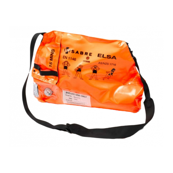
- Page 12 To use ELSA, the wearer places the carrying strap around the neck, pulls the flap of the bag open and dons the hood, where air is immediately available to the wearer. If the reducer/cylinder valve does not open when the wearer opens the bag flap, the quick-fire strap can be used to pull the actuating pin manually.
- Page 13 ELSA SERVICE SCHEDULE ELSA must be inspected / serviced annually by trained and qualified personnel, who may also be required to inspect, clean and maintain the apparatus on a monthly basis. Alternatively, monthly checks may also be performed by trained wearers. The...
- Page 14 ELSA MAIN SERVICE SCHEDULE ARTICLE DESCRIPTION YEAR 1 YEAR 2 YEAR 3 YEAR 4 YEAR 5 OR 10 HOOD (HD-3) 1032984 HOOD ASSEMBLY (ITEM 1) INSPECT INSPECT INSPECT INSPECT INSPECT 1032112 EXHALE VALVE & O-RING (ITEM 9) INSPECT INSPECT INSPECT...
- Page 15 ELSA FAULT-FINDING CHART COMPONENT SYMPTOM POSSIBLE FAULT REMEDIAL ACTION HOOD HOOD INFLATES EXHALE VALVE STICKING CLEAN/RENEW EXHALE VALVE EXCESSIVELY HOOD INCORRECTLY FITTED ADJUST HOOD AND RE-TEST HOOD DAMAGED RENEW HOOD LEAKING HOOD EXHALVE VALVE O-RING DRY OR CLEAN, LUBRICATE OR RENEW...
- Page 16 Refer to the relevant component Service Module for removal and servicing instructions of sub-assemblies. A list of all component Service Modules is given in Section 4 of this Module. WARNING: • Fully de-pressurise the pneumatic system prior to servicing pneumatic components of ELSA. • Wear suitable eye protection when working...
- Page 17 ELSA FIT CYLINDER INTO BAG Insert cylinder assembly (5) into bag (9) and locate contents gauge into slot at transparent window, so that gauge can be seen clearly when bag is closed. Feed approximately half of the breathing hose (7) into bag (9).
- Page 18 ELSA Withdraw U-Clip (4) and remove hood connector from inlet fitting on hood (1). FIT BREATHING HOSE CONNECTOR TO HOOD Check to confirm that hood connector is in good condition, clean and free from grease. Locate hood connector into inlet fitting on hood (1) and secure in position using U-Clip (4).
- Page 19 When servicing any of the pneumatic components or when cylinder has been disconnected, the apparatus must be subjected to a flow-test (see FS Module) and a leak-test (see LKT Module). Complete the ‘Routine Checks’ instructions detailed in the ELSA User Instruction Manual prior to returning the apparatus to service. ELSA...
- Page 20 ELSA INTENTIONALLY LEFT BLANK Issue F 11. 2009 ELSA (Page 9)
- Page 21 ELSA ASSEMBLY DIAGRAM AND PARTS LIST GENERAL ASSEMBLY Item Article No. Description Remarks Hood Assembly See HD Module Exhale Valve & O-Ring See HD Module Exhale Valve Cover See HD Module U-Clip See HD Module Cylinder Assembly Reducer/Cylinder Valve See RCV Module .
- Page 22 ELSA Issue F 11. 2009 ELSA (Page 11)
- Page 23 ELSA FIVE-YEAR SERVICE KIT Item Article No. Description Remarks 2002408 Five-year Service Kit ELSA (Page 12) Issue F 11. 2009...
- Page 24 ELSA Issue F 11. 2009 ELSA (Page 13)
- Page 25 HOOD HD-3 TECHNICAL DESCRIPTION This hood is fabricated in high-visibility, flame-retardant PVC or PVC-coated materials with a rubber neck seal. The outer surface of the hood is constructed from a uni-directional, stretch PVC-coated viscose fabric and incorporates spring steel ribs that shape the hood when worn. A closed-cell foam pad at the rear of the hood ensures that the inner mask is kept in permanent contact with the wearer’s face and that the hood moves with the head.
- Page 26 HD-3 HOOD SERVICING INSTRUCTIONS HOOD INSPECTION Clean and examine the hood material and neck-seal for splits, cracks, holes, or other wear and damage that may reduce respiratory protection. Examine the inner mask and associated components for signs of wear or damage.
- Page 27 HOOD HD-3 Push replacement exhale valve assembly (9) into exhale valve fitting (8). Fit exhale valve cover (12), ensuring that it 'clicks' into position. Issue B 10. 2009 HD-3 (Page 3)
- Page 28 HD-3 HOOD ASSEMBLY DIAGRAM AND PARTS LIST Item Article No. Description Remarks 1032984 Hood Assembly . Foam Pad . Retaining Nut . Backing Plate . Inner Mask . Backing Spring . Inlet Fitting . Exhale Valve Fitting 1032112 . Exhale Valve & O-Ring 1027929 ..
- Page 29 RCV-2 TECHNICAL DESCRIPTION This Module details the servicing procedures for the combined reducer/cylinder valve (RCV) for ELSA escape apparatus. The reducer/cylinder valve screws directly into a compressed-air cylinder using an M18 parallel thread, with an O-Ring providing the necessary seal.
- Page 30 RCV-2 REDUCER/CYLINDER VALVE TOOLS The following tools are required to service the reducer/cylinder valve: Item Article No. Description Remarks 1033841 Torque Wrench 1033800 Socket Handle 3/8” Square Drive 1033967 Crowfoot Spanner 27mm A/F 1033983 3/8” A/F Socket 3/8” Square Drive 1033999 Reducer Cap Tool 3/8”...
- Page 31 REDUCER/CYLINDER VALVE RCV-2 SERVICE SCHEDULE WARNING: DO NOT use spare parts designated for other types of apparatus. Confirm the identity of spare parts by comparing part numbers and shapes in the Assembly Diagrams and Parts Lists at the end of this Module. Note: •...
- Page 32 RCV-2 REDUCER/CYLINDER VALVE In the following schedule, the item number refers to the components depicted in Assembly Diagram and Parts List 5.3 provided at the end of this Module. DESCRIPTION YEAR 1 YEAR 2 YEAR 3 YEAR 4 YEAR 5 OR 10 HOSE ASSEMBLY (ITEM 1) LEAK-TEST &...
- Page 33 REDUCER/CYLINDER VALVE RCV-2 Withdraw U-Clip (6) and remove breathing hose (7) from reducer head (18). Remove foam ring (17) from reducer head (18). Remove O-Ring (8) from reducer head (18) using O-Ring Tool (I). Discard O- Ring. Withdraw pin bearing (13) from reducer head (18). Withdraw actuator U-Clip (9) from reducer head (18).
- Page 34 RCV-2 REDUCER/CYLINDER VALVE Use Reducer Cap Tool (E) fitted to Socket Handle (B) to unscrew reducer head (18). Remove reducer head (18) and withdraw piston assembly (21) and spring (26). Carefully inspect conical jet in reducer body (27) to ensure that it is clean and undamaged.
- Page 35 REDUCER/CYLINDER VALVE RCV-2 Carefully fit replacement piston seat (25), chamfered end first, into end of piston (22). Place seat on a clean, hard surface and ensuring that seat remains square to piston, push down on piston firmly until seat fully enters piston. Inspect seat to ensure that it is clean, undamaged and correctly inserted.
- Page 36 RCV-2 REDUCER/CYLINDER VALVE CAUTION: If the burst disc has been ruptured, the cylinder and valve should be examined to determine the cause and to ensure that the cylinder and valve are safe to use. REPLACING THE CONTENTS GAUGE O-RING AND RESTRICTOR Note: Bracketed numbers in this Section e.g: (4) refer to components depicted in Assembly...
- Page 37 REDUCER/CYLINDER VALVE RCV-2 Locate replacement restrictor (35) into position within contents gauge port, taking care to ensure that restrictor is seated correctly. Lightly lubricate replacement O-Ring (36) with Krytox Grease (K) and fit onto gauge spindle. Insert contents gauge (34) into reducer body (27) and secure with U-Clip (37). REPLACING THE CHARGING ADAPTOR Note: Bracketed numbers in this Section e.g: (4) refer to components depicted in Assembly...
- Page 38 RCV-2 REDUCER/CYLINDER VALVE Fit bonded seal (33) to charging adaptor body (31). Apply ONE drop of Loctite 542 (L) to adaptor body thread and screw charging adaptor assembly (29) into reducer body (27). Use Crowfoot Spanner (C) with Torque Wrench (A) set at 20 Nm to secure charging adaptor assembly (29).
- Page 39 REDUCER/CYLINDER VALVE RCV-2 REPLACING THE PRESSURE RELIEF VALVE O-RING Note: Bracketed numbers in this Section e.g: (4) refer to components depicted in Assembly Diagrams and Parts Lists 5.1 and 5.2. Remove spring (10) and relief valve with O-Ring (11) from reducer head (18) as described in Section 4.1 of this Module.
- Page 40 RCV-2 REDUCER/CYLINDER VALVE REPLACING THE ACTUATOR O-RINGS Note: Bracketed numbers in this Section e.g: (4) refer to components depicted in Assembly Diagrams and Parts Lists 5.1 and 5.2. Remove actuator assembly (14) from reducer head (18) as described in Section 4.1 of this Module.
- Page 41 REDUCER/CYLINDER VALVE RCV-2 Use Instrument Screwdriver (G) to remove U-Clip (4) from hood connector (3) and withdraw hose from connector. Use O-Ring Tool (I) to remove O-Ring (5) from hood connector (3). Discard O- Ring. Lightly lubricate replacement O-Ring (5) with Krytox Grease (K) and fit onto hood connector (3).
- Page 42 RCV-2 REDUCER/CYLINDER VALVE 4.10 RE-ASSEMBLING THE REDUCER/CYLINDER VALVE Note: Bracketed numbers in this Section e.g: (4) refer to components depicted in Assembly Diagrams and Parts Lists 5.1 and 5.2. Secure charging adaptor assembly (29), contents gauge (34), whistle flute & plug (38), and burst disc assembly (41) to reducer body (27) as described in the previous Sections of this Module.
- Page 43 REDUCER/CYLINDER VALVE RCV-2 Slide pin bearing (13) over actuator assembly (14) and into position within reducer head (18). Secure breathing hose (7) to reducer head (18) as described in Section 4.9 of this Module. Locate reducer cap (5) into position on reducer head (18) and secure with fixing screws (4) using Allen Key (H) until hand-tight.
- Page 44 RCV-2 REDUCER/CYLINDER VALVE ASSEMBLY DIAGRAM AND PARTS LIST REDUCER/CYLINDER VALVE WITHOUT BURST DISC Item Article No. Description Remarks 1030599 Reducer & Hose Assembly 1019634 . Circlip Pack of 5 1021926 . Actuator Disc Pack of 5 1021720 . Screw Pack of 10 1030581 .
- Page 45 REDUCER/CYLINDER VALVE RCV-2 Issue D 10. 2009 RCV-2 (Page 17)
- Page 46 RCV-2 REDUCER/CYLINDER VALVE REDUCER/CYLINDER VALVE WITH BURST DISC Item Article No. Description Remarks 2001200 Reducer & Hose Assembly 1019634 . Circlip Pack of 5 1021926 . Actuator Disc Pack of 5 1021720 . Screw Pack of 10 1030581 . Reducer Cap 1017800 .
- Page 47 REDUCER/CYLINDER VALVE RCV-2 Issue D 10. 2009 RCV-2 (Page 19)
- Page 48 RCV-2 REDUCER/CYLINDER VALVE BREATHING HOSE, CONNECTOR AND FITTINGS Item Article No. Description Remarks 1025109 Hose Assembly 2004034 O-Ring Pack of 5 2008616 Hood Connector 1017800 U-Clip Pack of 5 2015406 O-Ring Pack of 5 1022092 Silencer Pack of 5 RCV-2 (Page 20) Issue D 10.
- Page 49 REDUCER/CYLINDER VALVE RCV-2 TA0436 Issue D 10. 2009 RCV-2 (Page 21)
- Page 50 TOOLKIT TK-17 Item Article No. Description Remarks 2020530 Escape Tool Kit 2016479 . Torque Wrench 1/4” Square Drive 1033841 . Torque Wrench 3/8” Square Drive 1033934 . Adjustable Spanner 1033726 . Spanner 7mm x 8mm A/F 1033705 . Spanner 13mm x 17mm A/F 1034013 .
- Page 51 FLOW-SETTING AND TEST FS-2 TECHNICAL DESCRIPTION In the flow-setting and test, the constant flow of air from the reducer is set (if necessary) and the flow-rate checked over the duration of the cylinder supply. This Module details the procedure used for testing and flow-setting constant-flow escape apparatus.
- Page 52 FS-2 FLOW-SETTING AND TEST ASSEMBLING THE TEST EQUIPMENT Remove required components (see photograph on page 1 of this Module) from carrying case and place on a clean, dry, flat work surface. Remove fixing nut and washer from lower stud on reverse of flow-meter. Place fixings aside.
- Page 53 FLOW-SETTING AND TEST FS-2 TEST PROCEDURE CONNECT ESCAPE APPARATUS TO TEST EQUIPMENT Pull exhale valve cover to remove from exhale valve fitting on hood. Withdraw exhale valve assembly from exhale valve fitting on hood. Withdraw U-Clip and remove hood connector from inlet fitting on hood. Locate hood connector into port on test equipment and secure in position using U-Clip.
- Page 54 FS-2 FLOW-SETTING AND TEST DURATION AND FLOW TEST Ensure that escape apparatus is fully-charged. Pull firing pin on escape apparatus to begin constant flow of air. Activate Stop-watch and monitor duration and flow of air. Check that the flow of air remains greater than 30 litres per minute for at least: •...
- Page 55 FLOW-SETTING AND TEST FS-2 Note: If escape apparatus again fails the duration and flow test, refer to the Fault-finding Chart contained within the Product Module of this Manual and rectify accordingly. Re- test upon completion of rectification. WARNING: DO NOT use escape apparatus that fails the duration and flow test. Once apparatus has passed duration and flow test, seal flow-setting screw by applying a small amount of Loctite 542 sealant around screw head.
- Page 56 LEAK-TEST LKT-7 TECHNICAL DESCRIPTION The leak-test confirms that any leakage from the apparatus is within a safe and acceptable limit. This Module details the procedure for leak-testing constant-flow escape breathing apparatus. TEST EQUIPMENT This test requires the use of Leak-detection Fluid. TEST PROCEDURE Ensure that escape apparatus is fully-charged.
- Page 57 Scott Safety Limited Pimbo Road, West Pimbo, Skelmersdale, Lancashire, WN8 9RA, England. Tel: +44 (0) 1695 711711 Fax: +44 (0) 1695 711775...
Need help?
Do you have a question about the ELSA and is the answer not in the manual?
Questions and answers