Table of Contents
Advertisement
Advertisement
Table of Contents

Summary of Contents for Cavitar CAVILUX Smart
- Page 1 CAVILUX ® Smart Operating Manual...
-
Page 2: Table Of Contents
5.4.7 Troubleshooting......................28 MAINTENANCE AND SERVICE INFORMATION ............. 30 SUPPORT, ACCESSORIES AND END OF LIFE ..............31 LIMITED WARRANTY......................32 CAVILUX Smart, Operating Manual, Version 4.4 © 2011 Cavitar Ltd. All rights reserved. All unauthorized copying strictly prohibited. ® CAVILUX... -
Page 3: Introduction
Chapter 3 describes the properties of CAVILUX Smart and Chapter 4 deals with the installation of the system. Chapter 5 describes the operation of CAVILUX Smart. Please note that there is plenty of useful information related to the use of CAVILUX Smart in Section 5.4. As an example, troubleshooting is covered in Section 5.4.7. -
Page 4: Safety Information
ONLY A PERSON, WHO HAS CAREFULLY READ AND UNDERSTOOD ALL SAFETY INSTRUCTIONS BELOW AND THE REST OF THIS OPERATING MANUAL, IS QUALIFIED FOR USING CAVILUX SMART. CAVITAR LTD. IS NOT LIABLE FOR ANY DAMAGE CAUSED BY THE IMPROPER USE OF CAVILUX SMART. - Page 5 Do not expose the system to moisture, rain or condensing environment Excessive vibration or strong mechanical impact may damage the equipment o The operating temperature of CAVILUX Smart is +10…+40 °C. Do not expose CAVILUX Smart to excessively low or high temperatures...
- Page 6 • -operated master control for power on/off o only a person qualified for using CAVILUX Smart has the right to possess the key for the key-operated master control for power on/off the key has to be removed from the control unit when th e device is not in use.
-
Page 7: Properties
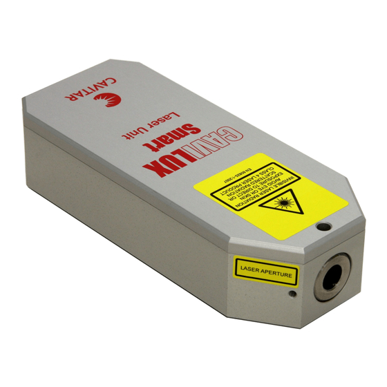
3 Properties CAVILUX Smart typically consists of the following components: LASER UNIT • class 4 laser product (see the yellow warning label on the laser unit) • laser aperture label • pulse power 200…500 W ± 10 % (see the device label on the bottom of the laser unit) •... - Page 8 ~0,5 kg Laser unit attachment 4 x M4 mounting holes, depth 4 mm CAVILUX Smart storage case dimensions 206 mm x 428 mm x 524 mm CAVILUX Smart system weight (incl. case) ~9 kg (depen ds on configuration) Environmental Storage temperature 0…+50 °C...
- Page 9 Fig. 3.1. Front panel of CAVILUX Control unit. Front panel controls: OFF/ON key-operated master control for power on/off START/STOP manual button for activating/disabling the outputs Front panel indicators: POWER green led indicates that the device is ON ACTIVE yellow/orange led indicates that the device is initializing (blinking), cooling (blinking) or activated (on), i.e.
- Page 10 +0…5 V, input impedance approximately 34 kΩ) D9 connector for external synchronization (only to be used together with Cavitar optical triggers) USB connector for programming the control unit with a computer Connector for remote interlock operation. The device will not emit...
- Page 11 Front Fig. 3.5. CAVILUX Smart laser unit (device label magnified on top). Fig. 3.6. Adjustable illumination optics (laser aperture and warning labels shown).
- Page 12 Fig. 3.7. Bottom view of control unit power supply. CAUTION! • Do not connect other than the supplied control unit power supply to the control unit. • Only connect the control unit power supply to a wall socket with protective grounding.
-
Page 13: Installation
4 Installation 4.1 Software installation If applicable, please uninstall old software version before installing new software version! Insert the CAVILUX Software CD into the CD drive and run the setup file. Follow the instructions on the screen. The screenshots below are valid for Windows XP. In case Windows logo test message box appears, please click "Continue Anyway"... - Page 14 Fig. 4.3. Choose "Install the software automatically" and click "Next". Fig. 4.4. Windows Logo test message box, click "Continue Anyway". The installation of CAVILUX Control software and CAVILUX drivers is completed. NOTE! • The software has to be installed before connecting the control unit to computer. •...
-
Page 15: Hardware Installation
Illumination optics contains a fiber optic light guide. This provides versatility for different illumination requirements. A focusing lens is installed to the end of the light guide for the generation of uniform illumination. Cavitar can also provide other illumination solutions such as back illumination or line illumination (see Chapter 6). - Page 16 TRIG IN connector of the control unit. Two TRIG IN connectors are available: an optical trigger provided by Cavitar shall be connected to the D9 connector o other trigger signals shall be connected to the BNC connector, allowed signal: TTL, 0…+5 V (input impedance approx.
- Page 17 NOTE! • To enable laser operation, the terminals of the Remote Interlock (RIL) connector (LEMO EPG.0B.302.HLN socket) need to be short-circuited together (do not connect to ground!). To disable operation, disconnect the terminals from each other. The device will not emit laser radiation when the terminals of the RIL connector are open-circuited (IEC/EN 60825-1).
-
Page 18: Operation
5 Operation After successful installation CAVILUX Smart is ready for operation. In the following the operation of the system is described in more detail. 5.1 Preliminary issues Before operation the following preliminary issues need to be performed: • check that laser unit, illumination optics and control unit are installed appropriately and that all optical surfaces are clean •... -
Page 19: General
5.2.1 General The front panel of the CAVILUX Control program is presented in Figs. 5.1 (Normal Mode) nd 5.2 (High Speed Mode). The software version in the figures contains eight output hannels, but the number of output channels can be e.g. two. Fig. -
Page 20: Choosing The Operation Mode
60 s cooling period will take place. It is possible to operate CAVILUX Smart at very high duty cycle (up to 90 %) for very short time (max. total laser active time 10 μs). Please see Section 5.4.5 for more details. -
Page 21: Programming Pulse Patterns
5.2.3 Programming pulse patterns CAVILUX Control program can be used to create new pulse patterns and to load or modify existing pulse patterns. The programming of a new pulse pattern begins by selecting File New. The pulse patterns are programmed in the ”Pulse Pattern” block. Odd channels are for cameras (Cam) and even channels for laser units (Laser). -
Page 22: Trigger Settings
5.2.4 Trigger settings After the pulse patterns have been programmed, it is time to choose trigger settings. CAVILUX Smart contains versatile trigger properties, which are described in more detail below. Trigger settings are set in the ”Trigger” block (cf. Fig. 5.1). -
Page 23: Power Settings
NOTE! • Max. repetition rate depends on the laser active time. When using external triggering, the control unit will ignore those trigger signals that appear at higher frequencies than allowed. For example, if the maximum repetition rate is 1 kHz, there has to be at least 1 ms duration between successive trigger signals. - Page 24 After the “Set” button has been pressed, the outputs can be activated by either: • clicking the ”Start” button in CAVILUX Control software (requires USB2 connection!), • pressing the Start/Stop button in the front panel of the control unit, or •...
-
Page 25: Example: Using Cavilux Control Software
300 times at 20 Hz frequency 5.3 After operation After the operation of CAVILUX Smart the following issues should be carried out: make sure that the outputs are disabled (ACTIVE led is off) turn the key-operated master control “OFF” and remove the key from the control unit... -
Page 26: Useful Information
5.4 Useful information 5.4.1 Spot sizes at different working distances Table 5.1 presents the diameter of the illuminated spot with different fiber core diameters, different illumination optics and at different working distances. All spot sizes are approximate values. Table 5.1. Spot sizes at different working distances. Fiber core Ø... -
Page 27: Maximum Repetition Rates For Different Pulse Durations
Note: With shortest pulse durations the actual pulse energy is lower due to rise and fall times. 5.4.4 Dependence of wavelength on temperature The output wavelength of CAVILUX Smart depends on temperature. Typically the output wavelength increases with increasing temperature by approximately 0,3 nm/°C. CAVILUX Smart has been characterized in normal room temperature (~20 °C). -
Page 28: Ultra High Speed Operation
In some applications there may be need for using the system at very high duty cycle for a short time. For this reason it is possible to use CAVILUX Smart at max. 90 % duty cycle provided that the total laser active time is max. 10 μs. For example, one can generate 10 pulses of 1 μs duration at max. - Page 29 o find out the optimal laser/camera delay by adjusting the respective delays in CAVILUX Control software (first “0” row in laser/camera channel, see Sections 5.2.3 and 5.2.7) o an optimal delay is found when: the image is bright and stable AND reducing the laser delay (or increasing the camera delay) by even a small amount makes the image darker and/or unstable (this ensures that the laser pulse is fired at the beginning of the camera exposure)
-
Page 30: Troubleshooting
(front illumination, side illumination, back illumination, mirror reflection, almost mirror reflection …) o note: the light output of CAVILUX Smart is essentially plane-polarized. The effect of polarization in the images can be checked by rotating the laser unit around the optical fiber (rotating the fiber doesn’t have any effect) - Page 31 a) check that all system components seem to be intact pay special attention to cables and connectors check the condition of the protective window of the illumination optics b) check that the fiber-optic light guide is intact if the fiber is broken or if the input or output end is dirty or damaged, the fiber will not transmit light properly.
-
Page 32: Maintenance And Service Information
6 Maintenance and service information CAVILUX Smart is essentially maintenance and service free so normally there is no need for these operations. However, sometimes there may be need to clean optical surfaces or casings or to replace the protective window of illumination optics. -
Page 33: Support, Accessories And End Of Life
It is not allowed to dispose CAVILUX products as unsorted municipal waste. CAVILUX products must be returned to your vendor or to Cavitar for proper disposal at the end of their ife. Alternatively one can consult local, state and federal regulations for proper disposal. -
Page 34: Limited Warranty
This limitation of liability does not apply to bodily injury or property damage for which Cavitar is held legally liable. In no event will Cavitar be liable for lost profits nor for incidental, consequential or other damages even if advised of the possibility of said damages.
Need help?
Do you have a question about the CAVILUX Smart and is the answer not in the manual?
Questions and answers