
Summary of Contents for Rion NC-72A
- Page 1 INSTRUCTION MANUAL Pistonphone NC-72A 3-20-41 Higashimotomachi, Kokubunji, Tokyo 185-8533, Japan http://www.rion.co.jp/english/...
- Page 3 Organization of this manual This manual describes the features and operation of the Pistonphone NC-72A. The manual contains the following sections. Outline Gives basic information on the unit. NC-72A Main Unit External View Contains drawings that show the pistonphone from all sides.
- Page 4 Reference Explains output level differences and compensation according to atmospheric pressure and microphone combinations, and explains the infl uence of radio frequency fi elds. Specifi cations Lists the technical specifi cations of the unit. This product can be used in any areas including residential areas. To conform to the EU requirement of the Directive on Waste Electrical and Electronic Equipment, the symbol mark on the right is shown on the instrument.
- Page 5 FOR SAFETY In this manual, important instructions are specially marked as shown below. To prevent the risk of damage to the unit or peripheral equipment, make sure that all instructions are fully understood and observed. Important These instructions are vital to prevent the possibility of damage to the prod- uct or of performance degradation.
- Page 6 Precautions • Read the documentation carefully, and operate the unit only as described in this manual. • Do not use or store the unit in locations which may be subject to splashes of water subject to high levels of dust subject to direct sunlight subject to vibrations or shock subject to air with high salt or sulphur content, to gases, or are in the vicinity of...
- Page 7 During operation, sound other than the 250 Hz tone may be heard, but this does not affect the performance of the unit. • The NC-72A is a precision product. Always handle it carefully and do not subject it to shocks. •...
-
Page 8: Table Of Contents
Contents Outline ......................1 NC-72A Main Unit External View ............... 2 Accessories External View ................3 Names of Parts and Functions ..............5 Coupler ....................5 Power supply section ................6 Side view and top view ................7 Operation ..................... 8 Inserting the batteries ................ -
Page 9: Outline
Outline The pistonphone NC-72A is a sound calibrator that conforms to IEC 60942:2003 (JIS C 1515:2004) class LS/C and class 1/C specifi cations. It uses a purely mechanical sound source with very low time-based variations which is capable of producing a sound of constant pressure and frequency unaffected by envi- ronmental changes (however, compensation of the output sound pressure level for static [atmospheric] pressure changes is required). -
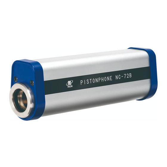
Page 10: Nc-72A Main Unit External View
NC-72A Main Unit External View PISTONPHONE NC-72A ### # SOUND CALIBRATOR Sound Pressure Level IEC 60942:2003 JIS C 1515:2004 Frequency 250 Hz Class LS/C and Class 1/C Ser. No. -
Page 11: Accessories External View
Accessories External View 1/4-inch adapter 1/2-inch adapter Six IEC LR6 (size AA) batteries Barometer... - Page 12 Accessories External View INSTRUCTION MANUAL Pistonphone NC-72A Carrying case Instruction manual (this document)
-
Page 13: Names Of Parts And Functions
Names of Parts and Functions Coupler Coupler Insert the microphone of the sound pressure measurement system (sound level meter) here. Use the 1/2-inch or 1/4-inch adapter as required to match the microphone dimensions. Coupler Important The coupler section also contains the piston part that generates sound pressure. If a foreign object enters the coupler, correct sound pressure and frequency are not assured. -
Page 14: Power Supply Section
Names of Parts and Functions Power supply section Battery compartment screw Battery voltage monitor (LED) Power switch Battery compartment screw Turn this screw to open the cover for battery replacement. Battery voltage monitor (LED) Enables to visually check the state of the batteries. Power switch Turns the unit on and off. -
Page 15: Side View And Top View
Names of Parts and Functions Side view and top view Sound pressure level indication (Specified sound pressure level at reference conditions) Serial number ### # SOUND CALIBRATOR Sound Pressure Level IEC 60942:2003 JIS C 1515:2004 Frequency 250 Hz Class LS/C and Class 1/C Ser. -
Page 16: Operation
Operation Inserting the batteries Battery compartment Battery label Screwdriver slot Battery compartment screw Six IEC LR6 (size AA) batteries Cover 1. Remove the cover from the unit. Insert a fl atblade screwdriver in the slot of the battery compartment screw and turn it counterclockwise to remove the cover. - Page 17 Operation Important - Make sure to insert batteries with correct +, - orientation as shown above. (The label in the battery compartment also indicates the polarity.) - A total of six batteries are required. - Do not mix old and new batteries. - Do not mix different battery types.
-
Page 18: Checking The Battery Voltage
Operation Checking the battery voltage The constant sound pressure generator in the unit uses an electronically controlled motor to drive a piston and create an accurate sinusoidal wave. Frequency precision is within ±1% provided that the battery voltage is between 7 volts and 10 volts. The battery voltage monitor (LED) allows the operator to check the state of the batteries, in order to assure correct performance. -
Page 19: Sound Pressure Measurement System (Sound Level Meter) Calibration
Operation Sound pressure measurement system (sound level meter) calibration 1. Verify that the power switch of the pistonphone is off. 2. Set the frequency weighting of the sound pressure measurement system (sound level meter) to "Z" or "C". 3. Select the measurement range of the sound pressure measurement system (sound level meter) so that 114 dB can be measured. - Page 20 Operation 5. After inserting the microphone into the pistonphone, wait at least 1 minute. Note If calibration is performed immediately after inserting the micro- phone, correct results can not be achieved due to the change in air pressure. You must wait about 1 minute until the pressure inside the microphone stabilizes.
- Page 21 Operation 8. Adjust the sound pressure measurement system (sound level meter) so that it reads 114 dB*. * The precise output sound pressure level (specifi ed sound pressure level for specifi c microphones) is given in the supplied calibration chart. At this time, compensation for the microphone effective load volume and static (atmospheric) pressure is required.
- Page 22 Operation 9. When level adjustment is completed, turn the power to the pistonphone off. 10. Carefully and slowly remove the microphone of the sound pressure measurement system (sound level meter) from the pistonphone. Important When removing the microphone from the pistonphone, always proceed very slowly and carefully, to avoid the possibility of damage to the microphone diaphragm caused by abrupt changes in air pressure.
-
Page 23: Using The Microphone Adapters
Operation Using the microphone adapters When the external diameter of the microphone is 1/2 inch or 1/4 inch, use the supplied 1/2-inch or 1/4-inch adapter. • Insert the adapter fully into the coupler. Otherwise correct calibration is not pos- sible. •... -
Page 24: Reference
Reference Output sound pressure level compensation The output sound pressure level generated by the pistonphone depends on a certain extent on the static (atmospheric) pressure and on the effective load volume that is applied due to the mounting of the microphone (this will differ according to the microphone type). When performing calibration, compensation for these two quantities must be provided to determine the exact output sound pressure level. - Page 25 Reference The output sound pressure level L (dB) is expressed by equation 2. Output sound pressure level L (dB) = 10 × log ....... Equation 2 Reference sound pressure 2 × 10 The output sound pressure level L (dB) with compensation for static (atmospheric) pres- sure is expressed by equation 3.
- Page 26 Reference Output sound pressure level compensation using supplied barometer The barometer supplied with this unit is a Class LS/C device that can be used to provide compensation of the sound pressure level for a static (atmospheric) pressure range of 905 hPa to 1055 hPa (90.5 kPa to 105.5 kPa).
- Page 27 Reference Microphone effective load volume and output sound pressure level change Depending on the microphone type, there will be a slight difference in output sound pres- sure level inside the coupler of the pistonphone. This is due to differences in the micro- phone prechamber volume and diaphragm equivalent volume, which cause a difference in the total volume of the coupler.
- Page 28 Reference Output sound pressure level change according to effective load volume (compensation values) (All compensation values in the table below apply to the microphone with grid attached.) Change Microphone type Remarks (compensation value, dB) UC-25 -0.08 1-inch microphone UC-27 -0.03 UC-34 -0.10 UC-26...
- Page 29 Reference Change for other brand microphones (compensation value, for reference) Change Microphone type Remarks (compensation value, dB) Tokyo Riko MR-103 +0.24 Tokyo Riko MR-103 +0.12 without grid 1-inch microphone B&K 4160 without +0.12 grid 1/2-inch microphone B&K 4180 0.00 Using 1/2-inch adapter (NC-72-S16)
- Page 30 Reference Output sound pressure level compensation (example) In actual use, the output sound pressure level generated by the pistonphone is calculated by applying compensation for the microphone effective load volume (differs according to microphone type) and the static (atmospheric) pressure. The output sound pressure level L (dB) is therefore obtained as follows.
- Page 31 Reference 2. When compensation value C for effective load volume of microphone is known Output sound pressure level L (dB) = L + 20 × log 101.325 : Specifi ed sound pressure level at reference conditions (as per calibration chart, Static pressure at time of use (kPa) Static pressure used for reference: 101.325 kPa...
- Page 32 Reference 3. When effective load volume of microphone is known 1-inch microphone Output sound pressure level L (dB) + (-0.00041 × (V - 960)) + 20 × log 101.325 1/2-inch or 1/4-inch microphone Output sound pressure level L (dB) + (-0.00041 × (V - 960)) + 20 ×...
- Page 33 Reference Example: Output sound pressure level L for 1/2-inch microphone with known effective load volume Specifi ed sound pressure level L at reference conditions: 114.05 dB (example, as per calibration chart) Static pressure at time of use P 98.8 kPa (example, measured with ba- rometer at time of use) Microphone effective load volume V : 224 mm...
-
Page 34: Electromagnetic Compatibility
Reference Electromagnetic Compatibility Reference orientation for testing effects of exposure to radio frequency fi elds: Opposite side of microphone insertion opening (see illustration below) Reference orientation for testing effects PISTONPHONE NC-72A of exposure to radio frequency fields... - Page 35 Reference Radio frequency emissions Electric fi eld strength of radio frequency emissions produced by the unit (quasi-peak value at a distance of 10 m) Frequency range 30 MHz to 230 MHz: 30 dB (reference 1 μV/m) or less Frequency range 230 MHz to 1 GHz: 37 dB (reference 1 μV/m) or less The confi guration for greatest radio frequency emissions: power ON...
- Page 36 Reference Immunity to power frequency and radio frequency fi elds Output sound pressure level deviation when placed under the infl uence of power frequency and radio frequency fi elds as specifi ed below: ±0.15 dB or less • Root-mean-square electric fi eld strength up to 10 V/m (non-modulated), frequency range 26 MHz to 1000 MHz, 900 Hz sinusoidal wave, 80% amplitude modulation •...
-
Page 37: Specifi Cations
Specifi cations Applicable standards IEC 60942:2003 (JIS C 1515:2004) "Electroacoustics - Sound Cal- ibrators" Class LS/C and Class 1/C (Class LS/C when using supplied barometer) Specifi ed microphones 1-inch microphones • IEC 61094-1 Type LS1P compliant microphones • IEC 61094-4 Type WS1P/F/D compliant microphones •... - Page 38 Specifi cations Reference conditions Ambient temperature 23°C Static (atmospheric) pressure 101.325 kPa Relative humidity 50% RH Microphone effective load volume 960 mm (total coupler volume 21245 mm (representative value)) Nominal sound pressure level 114 dB Specifi ed sound pressure level As noted in supplied calibration chart (114.0 dB ±0.2 dB (at refer- ence conditions)) Specifi ed sound pressure level tolerance limit...
- Page 39 Specifi cations Nominal frequency 250 Hz Specifi ed frequency As noted in supplied calibration chart Specifi ed frequency tolerance limit within ±1.0% (at reference conditions) Frequency stabilization interval After power-on: 5 s or less Frequency stability ±1.0% (within rated ambient conditions for use) (20 s, time window 1 s) THD (total harmonic distortion) of output sound pressure tolerance limit 2.5% or less (20 Hz to 20 kHz, within rated ambient conditions for...
- Page 40 Specifi cations 1/2-inch adapter (supplied) Model NC-72-S16 Load volume 909 mm (representative value) 1/4-inch adapter (supplied) Model NC-72-S06 Load volume 832 mm (representative value) Sound pressure level variation caused by microphone effective load volume variation -0.00041 dB/mm (representative value) Power supply Six IEC LR6 (size AA) alkaline batteries Power supply voltage Nominal: 9.0 V, Max.
- Page 41 Specifi cations Ambient temperature for storage -20°C to +60°C (no condensation) Ambient conditions for use Ambient temperature -10°C to +55°C Static (atmospheric) pressure 65 kPa to 108 kPa Relative humidity 10% to 90% (no condensation) Permissible ambient sound level 94 dB or less Electromagnetic compatibility EN 60942:2003 (JIS C 1515:2004, IEC 60942:2003), EN 61326-1:2013 (IEC 61326-1:2012)
- Page 42 Specifi cations Output sound pressure level compensation for static (atmospheric) pressure The output sound pressure generated by the NC-72A changes at a rate proportional to the static (atmospheric) pressure (See "Reference" section on page 17). To determine the exact output sound pressure...
- Page 43 Specifi cations Supplied accessories Carrying case NC-72-053 1/2-inch adapter NC-72-S16 1/4-inch adapter NC-72-S06 Barometer IEC LR6 (size AA) alkaline battery Instruction manual Calibration chart Inspection certifi cate...
- Page 44 Specifi cations PISTONPHONE NC-72A Unit: mm Dimensional Drawings...
- Page 46 No. 51693 15-11...
Need help?
Do you have a question about the NC-72A and is the answer not in the manual?
Questions and answers