Table of Contents
Advertisement
Quick Links
Advertisement
Table of Contents
Troubleshooting

Related Manuals for Faro FaroArm Quantum


Summary of Contents for Faro FaroArm Quantum
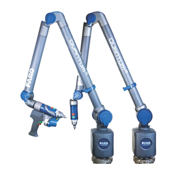
- Page 1 FaroArm and Laser ScanArm Quantum ® ® User Manual August 2017...
- Page 3 ANYONE FOR SPECIAL, COLLATERAL, INCIDENTAL, OR CONSEQUENTIAL DAMAGES IN CONNECTION WITH OR ARISING OUT OF THE PURCHASE OR USE OF THE FAROARM, FARO GAGE, FARO LASER TRACKER, FARO LASER SCANNER, FARO 3D IMAGER OR ITS MATERIALS. THE SOLE AND EXCLUSIVE LIABILITY TO FARO TECHNOLOGIES, INC., REGARDLESS OF THE FORM OF ACTION,...
-
Page 5: Table Of Contents
FaroArm Quantum ® August 2017 Table of Contents Chapter 1: Introduction General Information............3 6-Axis Quantum ................4 7-Axis Quantum ................6 Safety Labels ..............8 Pinch Points ..................8 Precautions ..............8 Regulatory Information ........... 9 Bluetooth ...................9 Wireless Local Area Network (WLAN 802.11).......10 Product Environmental Information ...... - Page 6 Wired connections ................ 39 USB....................40 Ethernet ..................40 Wireless Connections ..............40 FARO Wireless - Bluetooth............41 Using Bluetooth - Windows 10 ........... 41 Using Bluetooth - Windows 7 ............. 43 FaroArm Manager..............46 FARO Wireless - WLAN..............48 FaroArm Manager............
- Page 7 Laser Radiation Emission ............... 89 Serial Number Label ..............91 Servicing ..................91 Hardware Installation ..............91 Holding the FARO Laser Line Probe..........93 Pointing to a Surface ..............93 Hardware Controls and Indicators ..........94 Buttons ..................94 LED ....................94 Range Finder................
- Page 8 WLAN Primer................129 Independent BSS (IBSS)............129 Infrastructure BSS (BSS) ............. 130 Joining a WLAN ................ 130 Establishing a FARO WLAN Connection ........ 131 FARO i-Probe FAQ ............... 132 Quantum Performance Verification Checklist..132 Issues That Will Degrade Accuracy ..........132 Quantum Setup ................
- Page 9 FaroArm Quantum ® August 2017 Calibrated Artifact ..............140 Diagnosing FARO Laser Line Probe Accuracy Problems ..141 FARO Laser Line Probe Compensation ........142 Chapter 7: Product Specifications Chapter 8: Configuring the Quantum in CAM2 Measure Device Control Panel..........153 Add a Device ................154...
- Page 11 Representative by Phone, Fax or E-Mail. See “Technical Support” on page 161. Visit the FARO Customer Care area on the Web at www.faro.com to search our Knowledge Base. The Knowledge Base is available 24 hours a day, 7 days a week, and contains hundreds of solutions to product and application questions.
- Page 12 FaroArm Quantum ® August 2017 It is important that you understand the meaning of the following words before proceeding. digitize Indicates the recording of XYZ coordinates of a point or location in 3D space. The word digitize is the same as the term measure when referring to points.
-
Page 13: General Information
FaroArm Quantum ® August 2017 General Information The Quantum is a multiple-axis, articulated arm with a spherical working volume. Each joint has a rotary optical encoder. The signals from these encoders are processed, using advanced error coding and temperature compensation technology, and positional data is sent to the host computer using various wired and wireless communication protocols. -
Page 14: 6-Axis Quantum
FaroArm Quantum ® August 2017 6-Axis Quantum These are the key components and controls for the 6-Axis Quantum. Tube 1 Buttons Tube 2 Handle LED Storage Hook Probe Probe Locking Lever Base Collar Figure 1-1 6-Axis FaroArm front view Chapter 1: Introduction... - Page 15 FaroArm Quantum ® August 2017 Tube 2 WLAN On/Off Button Tube 1 Bluetooth On/Off Button Storage Hook Ethernet Port Buttons USB Port Handle LED Auxiliary Port Probe Powered USB Port ...
-
Page 16: 7-Axis Quantum
FaroArm Quantum ® August 2017 7-Axis Quantum These are the key components and controls for the 7-Axis Quantum. Tube 1 Probe Locking Lever Tube 2 Buttons Storage Hook Handle LED 7-Axis Handle (Removable) ... - Page 17 FaroArm Quantum ® August 2017 Tube 1 Power On/Off Button Tube 2 WLAN On/Off Button Probe Bluetooth On/Off Button 7-Axis Handle (Removable) Ethernet Port Handle Locking Collar USB Port Buttons ...
-
Page 18: Safety Labels
FaroArm Quantum ® August 2017 Safety Labels Notice the following safety labels on your Quantum. Pinch Points Labels that indicate pinch points are located on near the joints. Avoid placing hands and fingers in these pinch points. See Figure 1-5 for the location of the pinch point labels. -
Page 19: Regulatory Information
FaroArm Quantum ® August 2017 Regulatory Information Regulatory information for the wireless components of the Quantum is listed on the back of the base. Figure 1-6 Wireless regulatory information label Bluetooth FCC ID: Z64-WL1835MOD IC: 451l-WL1835MOD MIC: 201-135370 DECLARATION OF CONFORMITY FCC Compliance Statement: This device complies with Part 15 of the FCC rules. -
Page 20: Wireless Local Area Network (Wlan 802.11)
August 2017 • Consult the dealer or an experienced radio/television technician for help. CAUTION: Any change or modification not expressly approved by FARO Technologies, Inc. may void the user's authority to operate the equipment. DECLARATION OF CONFORMITY Industry Canada Statement: This device complies with RSS-210 of Industry Canada. - Page 21 Consult the dealer or an experienced radio/television technician for help. CAUTION: Any change or modification not expressly approved by FARO Technologies, Inc. may void the user's authority to operate the equipment. : The WLAN (802.11b/g) can be used concurrently with the USB Device, LAN (Ethernet) and Bluetooth ports.
-
Page 22: Product Environmental Information
FARO Technologies, Inc., as a producer of electrical and electronic equipment (EEE), has endeavored to meet these environmental responsibilities for managing WEEE. In so doing, FARO is providing the following to inform its customers about the WEEE collection process: In order to avoid any potential dissemination of hazardous substances into the... -
Page 23: Chapter 2: Setting Up The Quantum
The following components and accessories are standard items shipped with every system: Quantum - Packing List Shipping case Quantum Probe case: 3 mm i-Probe 6 mm i-Probe FARO Compensation Cone and T-shaped fixture FARO Compensation Sphere Chapter 2: Setting up the Quantum... -
Page 24: Optional Accessories
Optional Accessories The Accessories Manual that is on your FaroArm Manual USB flash drive lists all of the optional accessories that you can order from FARO. Installation and detailed operational instructions are included. The Accessories Manual is also available on FARO’s Web site at www.faro.com. -
Page 25: Shipping Case
Accessories Pocket Documentation Pocket 7-Axis Handle : The 7-Axis Handle is not available for 6-Axis Quantums. : The FARO Laser Line Probe HD case does not fit in the Shipping case. Figure 2-1 Quantum Shipping case Probe Case ... -
Page 26: Unpacking The System
FaroArm Quantum ® August 2017 Unpacking the System The Quantum is packed in a shipping case which includes space for the Cables, Probes, and mounting hardware. Lifting the Quantum Follow safe lifting procedures when removing the Quantum from its storage case. -
Page 27: Hardware Setup
FaroArm Quantum ® August 2017 Hardware Setup The following sections describe the proper setup of the Quantum system. This includes attaching the Quantum to your work surface or tripod, and connecting the Quantum to your computer. Mounting the Base The counterbalance by the tension spring generates torque at the base of the Quantum;... -
Page 28: Storage Hook
FaroArm Quantum ® August 2017 Storage Hook The Quantum has a Storage Hook attached to Tube 1 to secure Tube 2. This system helps secure the Quantum and helps prevent damage to the probe when in the rest position. Lift the last section upwards and insert the bottom of Tube 2 into the Storage Hook. -
Page 29: Installing Probes
FaroArm Quantum ® August 2017 Installing Probes Remove the Probe Kit case from the Shipping case. In addition to probes, this case contains the compensation cone.The probe attaches to the handle at the end of the Quantum. To install a probe: Hold the end of the Quantum on the underside with one hand and open the probe locking lever with your other hand. - Page 30 For more information, see “Probes” on page 55. : All FARO i-Probes have a unique serial number. After compensating an i-Probe, the compensation information stores on your computer. If you remove the i-Probe and reinstall it later, the Quantum automatically loads the compensation data.
-
Page 31: 7-Axis Handle
This handle stores in a cutout of the Shipping case foam. The 7-Axis Handle can be attached/detached while the Quantum is powered On. The FARO Laser Line Probe attaches in the same method. See “Hardware Installation” on page 91. To attach the handle: Loosen the locking collar. - Page 32 FaroArm Quantum ® August 2017 Insert the front edge of the 7-Axis Handle into the slot. Figure 2-11 Inserting the 7-Axis Handle Push the 7-Axis Handle in so that the connectors connect. Figure 2-12 Attaching the 7-Axis Handle Chapter 2: Setting up the Quantum...
- Page 33 FaroArm Quantum ® August 2017 Tighten the locking ring by turning it in the opposite direction. Tighten the ring until it clicks. Figure 2-13 Tightening the Locking Collar : Remove the 7-Axis Handle from the Quantum before packing. See “Packing the Quantum” on page 29. Chapter 2: Setting up the Quantum...
-
Page 34: Wired Connections
FaroArm Quantum ® August 2017 Wired connections The Quantum connects to the computer using a standard USB cable, or a standard Ethernet cable. High speed operation is supported. CAUTION: Complete all cable connections before applying power to the computer and the Quantum. ... -
Page 35: Supplying Power To The Quantum
FaroArm Quantum ® August 2017 Supplying Power to the Quantum Place the Quantum in an area with a properly grounded outlet receptacle. The On/Off button is located on the back side of the base. Connect the power supply cord to the port on the back side of the base. -
Page 36: Quantum Battery Pack
FaroArm Quantum ® August 2017 : Power surges, spikes, feedback, and fluctuation in the power source will affect the equipment and its electronic accessories. Please have your power source inspected by a professional to provide the cleanest power source possible. Quantum Battery Pack Your Quantum may be powered using the two supplied battery packs. - Page 37 FaroArm Quantum ® August 2017 Rotate the battery pack so that the slot is facing towards the right and the cloth tab is facing you. Slide the battery pack in with the slot to the inside. Figure 2-17 Installing the Battery Pack : Push the battery all the way in until it snaps into place.
-
Page 38: Removing The Battery Pack
WARNING: Only use the rechargeable battery pack supplied with your Quantum. For information on ordering additional or replacement battery packs, contact FARO’s Customer Service by Phone, Fax or E-Mail. See “Technical Support” on page 161. You can also charge a battery pack using the Quantum Battery Charging Base. -
Page 39: Packing The Quantum
Packing the Quantum The Quantum should be packed very carefully to prevent shipping damage. : The FARO Laser Line Probe HD case does not fit in the Shipping case. Turn off the Quantum, remove the battery pack, disconnect all cables, and unlock the handle so it is hanging down. -
Page 40: Usb Devices
FaroArm Quantum ® August 2017 USB Devices You can attach certain USB devices to the port on the rear of the base, This port is provided to charge USB devices. No data is sent to the device. Figure 2-21 Powered USB Port Chapter 2: Setting up the Quantum... -
Page 41: Auxiliary Port
Auxiliary Port On the rear of the Quantum base, an optional 9-pin communications port is available to connect external equipment. To get a list of approved FARO devices, contact your Customer Service Representative by Phone, Fax or E-Mail. See “Technical Support” on page 161. -
Page 42: Quantum Power Supply
Listed for US and Canada. For IEC member countries and Europe, the power supply must be certified for the country in which the equipment is sold. Contact FARO’s Customer Service to order a replacement. All servicing should be referred to qualified service personnel. -
Page 43: Surface Mount Plate Dimensions
The Surface Mount Plate is used to clamp or bolt the Quantum to a stable mounting surface. It is an assembly of a standard 3½” mounting ring and a FARO-designed base plate. You can bolt the Surface Mount Plate directly to a surface using the mounting screws in the Accessories Case. - Page 44 FaroArm Quantum ® August 2017 You can bolt the 3½” mounting ring directly to a surface using the mounting screws in the Probe case. Make sure to tighten each mounting screw to 100-inch pounds. Figure 2-24 Standard 3½” Mounting Ring dimensions Chapter 2: Setting up the Quantum...
-
Page 45: Numerical And Signal Processing
Referencing the Encoders ........................38 Host Computer ....................39 Wired connections ..........................39 Wireless Connections .........................40 FaroArm Manager ...................49 Devices ..............................50 Probes ..............................55 Using FARO i-Probes .........................57 Edit Probe ............................57 Probe Compensation Overview ......................58 Probe Compensation ...........................59 Configuration ............................76 Diagnostics ............................79 Temperature ............................83 Numerical and Signal Processing The Quantum contains a complete electronics system. -
Page 46: Handle Led
FaroArm Quantum ® August 2017 Handle LED After applying power to the Quantum, the Handle LED is Solid Yellow while an internal startup check runs. After this is complete, the LED indicates the following: • Flashing Blue - if the Quantum successfully communicates with the computer, and the encoders are not referenced. -
Page 47: Quantum Handle Buttons
FaroArm Quantum ® August 2017 Quantum Handle Buttons The Quantum Handle has two buttons and an LED. When a button is pressed, the LED light illuminates (green or red) and the host computer sounds. See “Handle LED” on page 36. Figure 3-1 Quantum Handle Buttons Use the Front button to collect readings and accept a measurement. -
Page 48: Referencing The Encoders
FaroArm Quantum ® August 2017 • The tube stress stop warnings - This warning appears when there is stress on one of the tubes or encoder joints. The stress stop warnings may be disabled. See “Hardware Configuration” on page 76. Figure 3-3 Quantum Stress Stop Warning : Other errors appear in a message box. -
Page 49: Host Computer
FaroArm Quantum ® August 2017 Host Computer The Quantum output is accepted through any PC-compatible computer using the following communication protocols: • USB 2.0 (Device) • Ethernet (802.3) • Bluetooth • Wireless Local Area Network (WLAN 802.11) You can use multiple communication protocols with the following limitations: •... -
Page 50: Usb
FaroArm Quantum ® August 2017 USB communication connects from the Quantum to the computer using a standard USB cable. High speed operation is supported. The USB connector is located on the back side of the base. Ethernet Ethernet communication connects from the Quantum to the computer using a regular or crossover twisted-pair Ethernet cable (Cat 5, Cat5e or Cat 6) with RJ- 45 connectors. -
Page 51: Faro Wireless - Bluetooth
FaroArm Quantum ® August 2017 FARO Wireless - Bluetooth The Quantum is a Bluetooth equipped device and can connect to your computer without using a cable. : The Bluetooth connection will not support Laser Line Probe use. Bluetooth wireless is a short-range communications technology intended to replace the cables connecting devices. - Page 52 FaroArm Quantum ® August 2017 Quantum to the Computer Connection Click Start > Settings. Figure 3-7 Windows Task Bar menu : You can also click the Bluetooth icon in the task bar menu and choose Add a Device. Choose B and then your Quantum.
-
Page 53: Using Bluetooth - Windows 7
August 2017 Click P Figure 3-9 Pairing the Quantum Enter the Quantum pairing code, faro, and click Next to create the SPP connection. Figure 3-10 Entering the Pairing Code The FaroArm driver connects to the SPP connection using the FaroArm Manager. - Page 54 FaroArm Quantum ® August 2017 Quantum to the Computer Connection Click Start > Devices and Printers. Figure 3-11 Windows Task Bar menu : You can also click the Bluetooth icon in the task bar menu and choose Add a Device. Choose Add a Device from the menu in the upper left corner of the window.
- Page 55 FaroArm Quantum ® August 2017 Enter the Quantum pairing code, faro, and click Next to create the SPP connection. Figure 3-14 Enter Device Pairing Code Windows checks and installs the hardware drivers. When this is complete, click the Devices and Printers link.
-
Page 56: Faroarm Manager
The FaroArm driver connects to the SPP connection using the FaroArm Manager. FaroArm Manager The FaroArm driver connects to the SPP connection using the FaroArm Manager utility software. To connect your Quantum using Bluetooth: Click Start > FARO > FaroArm Manager. Chapter 3: Operation... - Page 57 FaroArm Quantum ® August 2017 Choose Bluetooth. Figure 3-18 Choose the Bluetooth Connection In the Devices list, click your Quantum. : No more than two (2) Quantum pairings can be active at any one time, but any number can be defined. When the measuring software is launched (CAM2 Measure, Geomagic, Polyworks, etc.) the FaroArm driver attempts to use any Quantum connection - USB cable and any active Bluetooth pairings.
-
Page 58: Faro Wireless - Wlan
Quantum ® August 2017 FARO Wireless - WLAN The Quantum is a Wireless Local Area Network (WLAN) equipped device and can connect to your computer without using a cable. A WLAN is a series of interconnected computers that communicate with each other over the air waves rather than through a network cable connected to each computer. -
Page 59: Faroarm Manager
FaroArm Quantum ® August 2017 FaroArm Manager The FaroArm Manager is an application to control the Quantum settings and operation. Many measuring applications will directly connect and use sections of this application while connected to your Quantum. Figure 3-19 FaroArm Manager Chapter 3: Operation... -
Page 60: Devices
FaroArm Quantum ® August 2017 Devices The Devices group controls the connection settings between your Quantum and your computer. Figure 3-20 Connecting a Quantum In the A drop-down list, choose the type of connection: DAPTERS • • Bluetooth • WLAN •... -
Page 61: Usb
FaroArm Quantum ® August 2017 Choose USB if you connection is using a USB cable. Your Quantum will appear at the top of the D list. If necessary, click the R button to search the EVICES EFRESH computer for your Quantum. Figure 3-21 USB Connection •... -
Page 62: Bluetooth
FaroArm Quantum ® August 2017 Bluetooth Choose B if you connection is using the Bluetooth wireless LUETOOTH connection. Your Quantum will appear at the top of the D list. If EVICES necessary, click the R button to search the computer for your Quantum. EFRESH Figure 3-23 Bluetooth Connection : Ensure the Quantum’s Bluetooth On/Off button is on and your... -
Page 63: Wlan
FaroArm Quantum ® August 2017 WLAN Choose W if you connection is using the wireless ethernet connection. Your Quantum will appear at the top of the D list. If necessary, click the EVICES button to search the computer for your Quantum. EFRESH Figure 3-25 WLAN Connection : Ensure the Quantum’s WLAN On/Off button is on and your... -
Page 64: Ethernet
FaroArm Quantum ® August 2017 Ethernet Choose E if you connection is using an Ethernet cable. Your Quantum THERNET will appear at the top of the D list. If necessary, click the R button EVICES EFRESH to search the computer for your Quantum. Figure 3-27 Ethernet Connection •... -
Page 65: Probes
Compensate the current probe. • View the compensation log for the current probe. • Start the Single Point Articulation Test (SPAT). • Run an Arm Compensation or reset to the FARO Factory Arm Compensation. Figure 3-29 Probes dialog box Chapter 3: Operation... - Page 66 The OMPENSATION TATUS four standard probes for the Quantum (3 mm, 6 mm, Point and FARO Laser Line Probe) are created by default. Figure 3-30 Probe Information : If you do not see all of the probes, click Find to search the Quantum and your computer.
-
Page 67: Using Faro I-Probes
® August 2017 Using FARO i-Probes The standard 3 mm and 6 mm probes are FARO i-Probes. The exact diameter is electronically recorded on the i-Probe. You do not need to edit any parameters of the standard Quantum i-Probes. : This generation of FARO i-Probe will not attach to the FaroArm Edge, Platinum, or Fusion. -
Page 68: Probe Compensation Overview
FaroArm Quantum ® August 2017 Modify any settings and click Save to continue. Figure 3-33 Modify Probe dialog box The new probe is now current. You must compensate the new probe. Probe Compensation Overview Probe compensation is a localized process by which a measurement device is optimized to perform measurements accurately. -
Page 69: Probe Compensation
FaroArm Quantum ® August 2017 compensation fails, measurements will not be as accurate. Proper mounting and technique are critical compensation factors. Figure 3-34 Probe Compensation To optimize compensation and minimize stress-induced errors during this critical procedure, place the Quantum in a single position in which the elbow joint remains relatively stationary without any obstructions or restrictions in movement while the compensation is performed. -
Page 70: Hole Compensation Method - Guidance
FaroArm Quantum ® August 2017 Hole Compensation Method - Guidance Perform the Hole Compensation using the FARO probe compensation cone. If the G check box is selected for the current probe, use the following UIDANCE steps. Figure 3-35 Hole Compensation with Guidance Collect all of the points in this method by holding down the green Front button. - Page 71 FaroArm Quantum ® August 2017 the green Front button. Digitize at least 200 points in each of the ten different sweep positions. Place the ball probe in the compensation cone. Start in a vertical position. Press and hold the green Front button and move the handle down until the shaft of the probe is parallel with the top of the cone.
- Page 72 FaroArm Quantum ® August 2017 Digitize points in the hole and rotate the handle to position #4. Press the red Back button to finish. CAUTION: The probe must be well-seated in the hole when digitizing all compensation points. Even one or two poorly digitized points significantly affects the optimization process, which then has an effect on the accuracy of the Quantum.
-
Page 73: Hole Compensation Method
August 2017 Hole Compensation Method Perform the Hole Compensation using the FARO probe compensation cone or a 5 mm diameter machine drilled hole. The hole does not have to be exactly 5 mm, but it must be smaller than the probe’s diameter and have a smooth seat. - Page 74 FaroArm Quantum ® August 2017 Collect all of the points in this method by holding down the green Front button. The Quantum will collect points as fast as possible (“scanning”) until you release the green Front button. Place the ball probe in the compensation cone.
- Page 75 FaroArm Quantum ® August 2017 Digitize points in the compensation cone and sweep to position #3. • Press and hold the green Front button and move the handle down until the shaft of the probe is parallel with the top of the cone. : You must digitize at least 150 points.
- Page 76 FaroArm Quantum ® August 2017 The digitized compensation points then calculate and the C OMPENSATION updates. If the probe passes, the current date and time is added to the TATUS probe information. Figure 3-38 Compensation Results Chapter 3: Operation...
-
Page 77: Sphere Compensation Method - 6-Axis
FaroArm Quantum ® August 2017 Sphere Compensation Method - 6-Axis Perform the Sphere Compensation using a precision sphere or tooling ball. The sphere should be at least 10 mm (3/8 in) diameter or larger. You will digitize 45 individual points in three specific locations around the sphere by pressing the green Front button for each. - Page 78 FaroArm Quantum ® August 2017 affects the optimization process, which then has an effect on the accuracy of the Quantum. Move the handle so that the probe is pointing in position #1. Digitize 11 points around the top hemisphere of the sphere with the probe pointing in position #1.
- Page 79 FaroArm Quantum ® August 2017 Move the handle so that the probe is pointing in position #3, Digitize 11 points around the front hemisphere of the sphere with the probe pointing in position #2. Hold the handle in the same direction and orientation for every point.
-
Page 80: Sphere Compensation Method - 7-Axis
FaroArm Quantum ® August 2017 Sphere Compensation Method - 7-Axis Perform the Sphere Compensation using a precision sphere or tooling ball. The sphere should be at least 10 mm (3/8 in) diameter or larger. You will digitize 44 individual points in two specific locations around the sphere by pressing the green Front button for each. - Page 81 FaroArm Quantum ® August 2017 affects the optimization process, which then has an effect on the accuracy of the Quantum. Move the handle so that the probe is pointing in position #1. Digitize 11 points around the top hemisphere of the sphere with the probe pointing in position #1.
- Page 82 FaroArm Quantum ® August 2017 Move the handle so that the probe is pointing in position #2, Digitize 11 points around the front hemisphere of the sphere with the probe pointing in position #2. Hold the handle in the same direction and orientation for every point.
- Page 83 FaroArm Quantum ® August 2017 The digitized compensation points then calculate and the C OMPENSATION updates. If the probe passes, the current date and time is added to the TATUS probe information. Figure 3-42 7-Axis Sphere Compensation Results Chapter 3: Operation...
-
Page 84: View Log
FaroArm Quantum ® August 2017 View Log The M dialog box displays the compensation history of ANAGE OMPENSATION the current probe. You can set to active or delete any previous compensation. You can also copy the compensation values to the Windows clipboard. Figure 3-43 Compensation Log dialog box The previous probe compensations are compared to the current probe: •... - Page 85 FaroArm Quantum ® August 2017 • The 2 Sigma Error value is the deviation of all the points taken during the compensation. In order to pass compensation, this value has to be less than the single point accuracy specification of the Quantum. Figure 3-44 Quantum Accuracy Label •...
-
Page 86: Configuration
FaroArm Quantum ® August 2017 Configuration The Configuration group controls your Quantum’s general hardware and advanced connection settings. Hardware Configuration In the H dialog box you can: ARDWARE ONFIGURATION • View the current information about the Quantum. • Enable/disable Stress Stops and adjust the sensitivity. See “Error and Status Indicators”... -
Page 87: Network Configuration
FaroArm Quantum ® August 2017 • Centers Cursor - move the cursor to the center of the screen. • As Right Mouse Button - sends a right mouse button command to the computer. • As Center Mouse Button - sends a center mouse button command to the computer. - Page 88 FaroArm Quantum ® August 2017 Click Close to exit. Figure 3-46 Network Configuration dialog box Click the settings button next to each connection type to change the connection settings. Chapter 3: Operation...
-
Page 89: Diagnostics
Diagnostic Tilt command to test for any tilt in the base of the Quantum. Figure 3-47 Network Configuration dialog box Set up the FARO compensation cone approximately ⅔ of the Quantum's reach away from its base. Place a properly compensated probe firmly in the cone. -
Page 90: Diagnostics
FaroArm Quantum ® August 2017 Any deflection of the base is recorded and displayed on the screen. All of the points must be within the circle on the graph. • Rotate the mouse wheel to zoom in and out of the chart. Right-click and drag to move the chart around the window. -
Page 91: Diagnostic Level
FaroArm Quantum ® August 2017 Diagnostic Level Click D to compare the Quantum to level. This command uses IAGNOSTIC EVEL the Quantum’s internal inclinometer. The Quantum should never lean more than ±5° from level. Figure 3-49 Diagnostic Level dialog box Look at and adjust the mounting until the white dots are centered in each bubble. -
Page 92: Diagnostic Tilt
FaroArm Quantum ® August 2017 Diagnostic Tilt Click D to check for any tilt in the base of the Quantum. This IAGNOSTIC command uses the Quantum’s internal inclinometer. Figure 3-50 Diagnostics dialog box Move the tubes and joints of the Quantum. •... -
Page 93: Temperature
FaroArm Quantum ® August 2017 Temperature The Temperature group controls is a set of commands for checking your Quantum’s internal temperature. Temperature Graph Click T to view the recorded temperature of the Quantum EMPERATURE RAPH over a long period of time. Figure 3-51 Temperature Graph dialog box •... -
Page 94: Temperature Stability
FaroArm Quantum ® August 2017 Temperature Stability Click T to view the ambient temperature change of the EMPERATURE RAPH Quantum over time. Figure 3-52 Temperature Stability dialog box • Rotate the mouse wheel to zoom in and out of the chart. Right-click and drag to move the chart around the window. -
Page 95: Quantum Ball Probes
Custom Probe Compensation ................112 Quantum Ball Probes The Quantum uses the FARO i-Probe. This is an electronically serialized intelligent probe that automatically provides its actual exact ball diameter to the Quantum and monitors probe body temperature to compensate for thermal deformation. -
Page 96: Note
For more information, see “Probes” on page 55. : All FARO i-Probes have a unique serial number. After compensating an i-Probe, the compensation information stores on your computer. If you remove the i-Probe and reinstall it later, the Quantum automatically loads the compensation data. -
Page 97: Custom Probes
The Quantum probe thread size is 1.40” - 32 UNS - 2B. • The base of the probe should follow the shape of the FARO probes. • The custom probe will thread onto the end of the handle and tighten with a 12 mm wrench. -
Page 98: Faro Laser Line Probe Hd
: The FARO Laser Line Probe only connects to a 7-Axis Quantum. Computer Requirements The FARO Laser Line Probe will generate thousands of points in a short amount of scanning time. For best results, your computer must have a powerful Central Processing Unit (CPU) and a large amount of Random Access Memory (RAM). -
Page 99: Laser Safety
Laser Radiation Emission When the FARO Laser Line Probe is operating, a laser beam emits from the aperture at the front of the FARO Laser Line Probe. See Figure 4-4 for the location of the laser beam aperture. Figure 4-4 Laser Aperture... - Page 100 FARO Laser Line Probe HD Laser power up to 18 mW at 450 nm in a diverging beam could be accessible in the interior of the FARO Laser Line Probe. WARNING: DO NOT ATTEMPT TO OPEN THE FARO LASER LINE PROBE CASE.
-
Page 101: Serial Number Label
PROBE CASE. THERE ARE NO USER-SERVICEABLE PARTS. Hardware Installation The FARO Laser Line Probe is stored in a separate Shipping case. Installing it is similar to the Quantum 7-Axis Handle. See “7-Axis Handle” on page 21. The FARO Laser Line Probe can be attached/detached while the Quantum is powered : The FARO Laser Line Probe HD does not fit into the Shipping case. - Page 102 Figure 4-8 Attaching the 7-Axis Handle Tighten the locking ring by turning it clockwise. Do not over-tighten the ring. : Remove the FARO Laser Line Probe from the Quantum before packing. See “Packing the Quantum” on page 29. Chapter 4: Probes...
-
Page 103: Holding The Faro Laser Line Probe
Never grab the FARO Laser Line Probe while measuring. Simply hold the pistol grip. : Avoid touching the lenses. When necessary, clean the left and right lenses with the cloth from the FARO Laser Line Probe case. Dirt and grease on either lens can cause poor results. Pointing to a Surface The following figure shows the orientation of the FARO Laser Line Probe to the surface. -
Page 104: Hardware Controls And Indicators
The FARO Laser ScanArm (Quantum with FARO Laser Line Probe) uses the green Front and red Back buttons and the Handle LEDs. Buttons Use the buttons on the Quantum handle or the buttons on the FARO Laser Line Probe handle to control measuring. •... - Page 105 When the Laser Line Probe is out of range, the cross hair and the laser line no longer touch. You can switch the Range Finder off in the FARO L ASER ROBE ONTROL dialog box.
-
Page 106: Range Finder Dialog Box
Figure 4-10 Laser Line Probe in range Figure 4-11 Laser Line Probe not in range When the FARO Laser Line Probe is within the operating range, the center of the target displays as a small box in the R dialog box, see Figure 4-10. -
Page 107: Software Setup
FARO Laser Line Probe. : When necessary, clean the top and bottom lenses with the cloth from the FARO Laser Line Probe case. Dirt and grease on either lens can cause poor results. Open CAM2 Measure. From the D... -
Page 108: Plane Compensation
Plane Compensation Calibrate the FARO Laser Line Probe. You will digitize the FARO Compensation Plate, once with the ball probe, and then three times with the FARO Laser Line Probe. Digitize the white area of the FARO Compensation Plate with the ball probe. - Page 109 Figure 4-14 Measuring the Compensation Plate with the Ball Probe : Avoid touching the lenses. When necessary, clean the top and bottom lenses with the cloth from the FARO Laser Line Probe case. Dirt and grease on either lens can cause poor results.
- Page 110 Click Start Compensation. Digitize the white area of the FARO Compensation Plate with the FARO Laser Line Probe in a sweeping motion. You should collect at least 200 scan lines in the FARO Laser Line Probe compensation. If not, repeat the compensation moving the FARO Laser Line Probe slower in each step.
- Page 111 Center Range • Press and hold the green Front button and move the FARO Laser Line Probe while pointing to the center of the white surface. Rotate the FARO Laser Line Probe as much as possible - at least 90 degrees.
- Page 112 • Aim the laser line at the middle of the white surface. • Move the FARO Laser Line Probe until the laser is closer than the Near Range • Press and hold the green Front button and slowly move the FARO...
- Page 113 Figure 4-16 Laser Line Probe Compensation Results You now have two probes to digitize your part. Use the Probe Management command to switch between the standard ball probe and the FARO Laser Line Probe. : If you remove the FARO Laser Line Probe, you must re-calibrate it again to guarantee the accuracy of the measurements.
-
Page 114: Dro
• If the FARO Laser Line Probe is in range, the X, Y, Z coordinate is the center of the laser line. Note that this may not be the center of the complete laser line because some part of the laser line may be out of range. - Page 115 FaroArm Quantum ® August 2017 In the E dialog box, you will see all of the information about the ROBE FARO Laser Line Probe: Figure 4-19 Modify Probe dialog box Chapter 4: Probes...
- Page 116 FaroArm Quantum ® August 2017 When the FARO Laser Line Probe is within the operating range, you will see the line in the P of the dialog box. REVIEW Figure 4-20 FARO Laser Line Probe Control dialog box • Disable the Range Finder Laser box by clearing the R...
- Page 117 Scan Rate - choose the number of scan lines per second. 1/1 is the normal rate of scan lines per second, set this to discard scan lines. : Always set the scan rate to 1/1 when calibrating the FARO Laser Line Probe.
- Page 118 NTENSITY the proper saturation level. : FARO recommends this algorithm for the compensation of the FARO Laser Line Probe HD. For more information, see “FARO Laser Line Probe Compensation” on page 97. • Automatic - High Contrast (HDR): This is an automatic mode to scan high-contrast surfaces such as a black and a white surface.
-
Page 119: Additional Considerations
Keep in mind that given the vast range of colors, textures and finishes, there is no exact science for these FARO Laser Line Probe Settings that work best on a particular surface. Finding the optimum settings may require some practice. -
Page 120: Quantum Tp-20 Probe Kit
FaroArm Quantum ® August 2017 Handle. Simply attach this assembly just as you would any other probe. See “Installing Probes” on page 19. The Renishaw TP-20 touch-trigger probe automatically digitizes a point by touching the stylus to the part. : The Renishaw TP-2 Probe is not supported. Quantum TP-20 Probe Kit The Quantum TP-20 Probe Kit contains: •... -
Page 121: Probe Modules For The Tp-20 Probe
Ensure the Auxiliary port is active and the De-bounce Time is not zero (0). See “Edit Probe” on page 57. Compensate the probe using the FARO Compensation Sphere, or any precision sphere, after installation. For more information, see “Sphere Compensation Method - 6-Axis” on page 67 or “Sphere Compensation Method - 7-Axis”... -
Page 122: Custom Probe Compensation
FaroArm Quantum ® August 2017 Custom Probe Compensation Any probe with a sphere or a point can be compensated. See “Probe Compensation” on page 59. Chapter 4: Probes... -
Page 123: Chapter 5: Accuracy
This may be done through mechanical adjustments, as well as software corrections. Specialists at FARO’s production facility perform the factory compensation. This compensation utilizes patented hardware and software (not available to the user) to determine the true dimensions and kinematics of the Quantum. The results of... -
Page 124: Iso 10360 Standard
Any of these problems require FARO’s Customer Service Department to disassemble the Quantum, repair the necessary item(s), and perform a factory compensation. -
Page 125: Iso 10360-8 Standard
FaroArm Quantum ® August 2017 - Sphere Probing Form Error. The operator Form measures a sphere with the Quantum probe. The error is maximum distance of any point from the best-fit sphere. - Sphere Location Diameter Error. The operator measures a sphere with the Quantum probe from multiple orientations. -
Page 126: Repeatability
® August 2017 If any test fails, print the results and repeat the calibration two more times. Print all of the results and contact FARO’s Customer Service by Phone, Fax or E-Mail. See “Technical Support” on page 161. Repeatability Perform the Single Point Repeatability Test to check repeatability (SPAT) of the Quantumusing a hole or a cone. -
Page 127: Loss Of A Degree Of Freedom
FaroArm Quantum ® August 2017 The specifications (SPAT and E ) of your Quantum are listed on the label between the battery pack slots. Figure 5-1 Quantum Accuracy Label : For optimum performance, correctly mounting and operating the Quantum is very important. For more information, see “Quantum Performance Verification Checklist”... -
Page 129: Chapter 6: Maintenance And Troubleshooting
Mounting ............................136 Single Point Articulation Test (SPAT) .....................138 User Compensation ...........................139 Calibrated Artifact ...........................140 Diagnosing FARO Laser Line Probe Accuracy Problems ...............141 FARO Laser Line Probe Compensation ...................142 Normal Maintenance Quantum The Quantum is a precision measurement device that contains many sensitive components, and it should be handled with care. -
Page 130: Host Computer
Periodic calibration tests should be completed to certify the Quantum accuracy and repeatability. See “Quantum Calibration” on page 115. FARO recommends you return your Quantum to a service center, once a year, for our annual calibration and a 15 point check up. Host Computer The computer is an electronic device containing many sensitive components. - Page 131 FaroArm Quantum ® August 2017 the counterbalancing mechanism. The reaction forces will result in deformations in the mounting, which degrade the performance of the Quantum if the deformations are sufficiently large. The primary forces encountered due to counterbalancing are translation and torsion.
-
Page 132: Temperature Considerations
August 2017 Temperature Considerations FARO was awarded the U.S. patent #5,402,582, and worldwide patents are pending, on the concept and the methods for temperature compensation of portable CMM devices. This brief overview is meant only as the most general of descriptions. - Page 133 FaroArm Quantum ® August 2017 Wrist Straps - Wrist straps fit snugly around a person’s wrist and are connected to an ESD ground point (never earth ground) or to a grounded mat. A poor connection with a wrist strap is associated with a loose fit or dry skin (use an ESD lotion for dry skin).
-
Page 134: Troubleshooting
Troubleshooting Error message on host computer. • Contact FARO’s Customer Service by Phone, Fax or E-Mail. See “Technical Support” on page 161. Have the message ready. Probe compensation fails. •... -
Page 135: Hardware Communication Issues
FaroArm Quantum ® August 2017 • Check the cables and connectors for bent pins or damage and ensure that the connectors are secure. Replace all cables that show signs of damage. • Check the power source (outlet) for proper voltage, current and grounding. For more information, see “Quantum Power Supply”... -
Page 136: Faro Wireless Connection Issues
• You have set up your connection using your platform specific Bluetooth Wizard and the FARO Bluetooth Connection Setup utility, but software application does not find the Quantum. Ensure sure the Quantum is receiving power and the On/Off button is set to the ON position. -
Page 137: Wlan
FARO Wireless FAQ • How fast is the connection? 1 Megabit/second. • What is the range of the FARO Wireless connection? Approximately 30 feet or 10 meters. • How many simultaneous Bluetooth wireless connections can be established with the FaroArm driver? - Page 138 No. If both are properly connected, the Bluetooth wireless will be the only active connection for that Quantum. • Can I use a FARO Laser Line Probe with the FARO Wireless connection? Yes. • Can I add a Bluetooth wireless connection while the FaroArm driver is...
-
Page 139: Wlan Primer
FaroArm Quantum ® August 2017 • Can I use all of the communication options at the same time? You can use multiple communication protocols with the following limitations: • USB, Ethernet, and Bluetooth are active at the same time, WLAN is disabled •... -
Page 140: Infrastructure Bss (Bss)
Association Identifier (AID - logical port) at this time. Authentication Apply Security - establish a secure wireless network. WPA2-Personal is recommended for the FARO WLAN security (based on IEEE 802.11i and Advanced Encryption Standard -AES). The password is the real key to security! -
Page 141: Establishing A Faro Wlan Connection
FaroArm Quantum ® August 2017 Establishing a FARO WLAN Connection There are a minimum of three STAs to be configured. This may be performed in any order but the typical order is: Set up an Access Point Set up the Quantum... -
Page 142: Faro I-Probe Faq
Quantum Performance Verification Checklist If you are experiencing accuracy or repeatability problems with your Quantum or FARO ScanArm system, this section details proper setup techniques to help you identify the potential sources of error. It is important to clearly understand all the “do's and don'ts” in order to get the most out of every Quantum and ScanArm. -
Page 143: Quantum Setup
DO NOT do short sweeps with the FARO Laser Line Probe during compensation. • Dirty lens. • Clean the top and bottom lenses with the cloth from the FARO Laser Line Probe case. Dirt and grease on either lens can cause poor results. Probes • Measuring with Point Probes. - Page 144 FaroArm Quantum ® August 2017 • In CAM2 Measure, run the Devices > Hardware Configuration command and click Temperature. Figure 6-4 Temperature Stability dialog box • For more information, see “Temperature Stability” on page 84. Chapter 6: Maintenance and Troubleshooting...
-
Page 145: Probe Setup
FaroArm Quantum ® August 2017 Probe Setup Figure 6-5 Installing a Probe Check probe seating. Install by hand. Verify that the probe has no chips or cracks, is not loose, and that it has no flat spots. Probe Compensation ... -
Page 146: Mounting
FaroArm Quantum ® August 2017 Look in the probe compensation log and compare the X, Y and Z values. Each value should repeat to within the accuracy of the device. Figure 6-7 Probe Compensation Log : If one person is able to repeat better than another person, review probe compensation procedure. -
Page 147: Base Deflection
Start the FaroArm Manager software and connect your Quantum. Click Diagnostics > Base Deflection. Set up the FARO compensation cone, or a hole on your part, approximately ⅔ of the Quantum's reach away from its base. Place a properly compensated probe firmly in the cone. The probe must be well-seated in the hole. -
Page 148: Single Point Articulation Test (Spat)
Quantum's X, Y and Z coordinates throughout its range of motion. Set up the FARO compensation cone, or a hole on your part, approximately ⅔ of the Quantum's reach away from its base. In CAM2 software, start the SPAT routine from the D... -
Page 149: User Compensation
FaroArm Quantum ® August 2017 The SPAT automatically completes. The set of measurements from each sweep are compared for repeatability. If the sets are not repeatable, you must repeat the test. : The Quantum movement should feel fluid. Be careful not to stress the Quantum while taking these points or get too close to an end stop since stresses can be amplified near end stops. -
Page 150: Calibrated Artifact
No button to save the new arm compensation. The new arm compensation will remain in your Quantum until changed or reset. Click the Reset button to restore the FARO Factory compensation. Repeat SPAT Repeat the SPAT with the compensation cone or conical socket in a different location. -
Page 151: Diagnosing Faro Laser Line Probe Accuracy Problems
If the Quantum is not mounted correctly, or the hard probe is not accurately compensated, then the FARO Laser Line Probe will produce inaccurate results. Clean the top and bottom lenses with the cloth from the FARO Laser Line Probe case. Dirt and grease on either lens can cause poor results. -
Page 152: Faro Laser Line Probe Compensation
ASER ROBE ONTROL Perform the compensation at least 3 times. See “FARO Laser Line Probe Compensation” on page 97. When sweeping from side to side and front to back, make sure you sweep through at least 90 degrees. - Page 153 Z: 50 µm (0.0019 in) If additional support is required, contact your Customer Service Representative by Phone, Fax or E-Mail. See “Technical Support” on page 161. When contacting FARO’s Customer Service, please provide the following information: The serial number of the device(s).
-
Page 155: Chapter 7: Product Specifications
Chapter 7: Product Specifications This chapter contains the Quantum technical specifications and rated conditions for operation. For other FARO FaroArm models, please consult the original User Manual that shipped with your FARO FaroArm or contact FARO Customer Service by Phone, Fax or E-Mail. See “Technical Support” on page 161. - Page 156 FaroArm Quantum ® August 2017 Size Shipping 6-Axis Weight Quantum Shipping Case 1.5 M length 114.5 cm 40.9 cm 33 cm 26.0 kg 45.1 in 16.1 in 13.0 in 57.3 lb 2.5 M length 114.5 cm 40.9 cm 33 cm 27.1 kg 45.1 in 16.1 in...
- Page 157 FaroArm Quantum ® August 2017 Size Weight FARO Laser Line 190 mm 177 mm 133 mm 0.5 kg Probe HD 7.5 in 7.0 in 5.2 in 1.1 lb Size Shipping Weight FARO Laser Line 29.7 cm 23.1 cm 16.5 cm 1.9 kg...
- Page 158 FaroArm Quantum ® August 2017 Quantum Rated Conditions Operating Temperature Range 10°C to 40°C 50°F to 104°F Storage Temperature Range -20°C to 70°C -4°F to 122°F Temperature Rate 3°C/5 min 5.4°F/5 min Operating Humidity Minimum 0% RH, Maximum 95% RH Storage Humidity Minimum 0% RH, Maximum 100% RH Barometric Pressure Range...
- Page 159 FaroArm Quantum ® August 2017 ISO 10360-12 Maximum Quantum Accuracy Permissible Error (MPE) 6-Axis 1.5 M length Volumetric Accuracy (E 0.023 mm (0.0009 in) Single Point Repeatability (SPAT) 0.012 mm (0.0005 in) 0.008 mm (0.0003 in) Size 0.015 mm (0.0006 in) Form 0.027 mm (0.0011 in) 2.5 M length...
- Page 160 FaroArm Quantum ® August 2017 ISO 10360-12 Maximum Quantum Accuracy Permissible Error (MPE) 7-Axis 2.5 M length Volumetric Accuracy (E 0.032 mm (0.0013 in) Single Point Repeatability (SPAT) 0.022 mm (0.0009 in) 0.012 mm (0.0005 in) Size 0.025 mm (0.0010 in) Form 0.048 mm (0.0019 in) 3.5 M length...
- Page 161 FaroArm Quantum ® August 2017 ISO 10360-12 Maximum Quantum Accuracy Permissible Error (MPE) 6-Axis 1.5 M length Volumetric Accuracy (E 0.028 mm (0.0011 in) Single Point Repeatability (SPAT) 0.018 mm (0.0007 in) 0.012 mm (0.0005 in) Size 0.020 mm (0.0008 in) Form 0.034 mm (0.0013 in) 2.5 M length...
- Page 162 FaroArm Quantum ® August 2017 ISO 10360-12 Maximum Quantum Accuracy Permissible Error (MPE) 7-Axis 2.5 M length Volumetric Accuracy (E 0.042 mm (0.0017 in) Single Point Repeatability (SPAT) 0.028 mm (0.0011 in) 0.020 mm (0.0008 in) Size 0.035 mm (0.0014 in) Form 0.060 mm (0.0024 in) 3.5 M length...
-
Page 163: Chapter 8: Configuring The Quantum In Cam2 Measure
FaroArm Quantum ® August 2017 Chapter 8: Configuring the Quantum in CAM2 Measure This chapter describes the operation of your Quantum with CAM2 Measure v10, or later. Most of these commands start items from the FaroArm driver and are available in other software packages. For more information in starting these commands in other software packages, see the FaroArm section in your software manual. -
Page 164: Add A Device
FaroArm Quantum ® August 2017 • Click the << button to show the list of devices. Add a Device From the D panel, click the Add New Device button. Select an EVICE ONTROL eligible device from the A dialog and click Connect. EVICE Ethernet and Wireless If you are connecting to the computer using the Bluetooth, WLAN, or Ethernet,... -
Page 165: Hole Compensation
FaroArm Quantum ® August 2017 Hole Compensation From the D panel, click the Probe Compensation Point button EVICE ONTROL to compensate the probe. For more information, see “Hole Compensation Method” on page 63. Sphere Compensation From the D panel, click Probe Compensation Sphere to EVICE ONTROL compensate the probe. -
Page 166: Diagnostics
FaroArm Quantum ® August 2017 Diagnostics From the D panel, click Diagnostics to show the Quantum EVICE ONTROL dialog box. IAGNOSTICS Figure 8-4 Diagnostics dialog box For more information, see “Diagnostics” on page 80. Chapter 8: Configuring the Quantum in CAM2 Measure... -
Page 167: Temperature
FaroArm Quantum ® August 2017 Temperature From the D panel, click Temperature to show the EVICE ONTROL dialog box. EMPERATURE Figure 8-5 Temperature Stability dialog box For more information, see “Temperature Stability” on page 84. Measurement Mode Setting From the D panel, click the Measurement Mode Setting button EVICE ONTROL... -
Page 168: Measuring With The Quantum
FaroArm Quantum ® August 2017 • Distance Interval: press the green Front button, or the G key, to start the distance interval. Collect a single reading when the probe moves a distance. Choose this option, enter the distance value and press OK. •... -
Page 169: Adding Readings
FaroArm Quantum ® August 2017 Adding Readings Use commands to control the Quantum instead of hardware buttons. Buttons (and their associated hot keys) on the M panel are used for recording a EASUREMENT reading (G key), recording an end click (H key), and removing the last reading (Backspace key). -
Page 171: Technical Support
Be sure to read the relevant sections of the documentation to find the help you need. • Visit the FARO Customer Care area on the Web at www.faro.com to search our Knowledge Base. This is available 24 hours a day 7 days a week. •... - Page 172 +82.51.662.3413 (Worldwide) North America: +1 407 562 5294 Europe: +800 3276 1737, +49 7150 9797-9400 (Worldwide) Asia: 65 65430111 Japan: +81 561 63 1412 China: +86 021 61917600 India: +91-11-46465660 Thailand: +662.7443178 Korea: +82.51.941.8170 E-Mail North America: support@faro.com Europe: support@faroeurope.com Asia:...
- Page 173 Japan: supportjapan@faro.com China: supportchina@faro.com India: supportindia@faro.com Thailand: supportthailand@faro.com Korea: supportkorea@faro.com E-Mails or Faxes sent outside regular working hours usually are answered before 12:00 p.m. the next working day. Should our staff be on other calls, please leave a voice mail message; calls are always returned within 4 hours. Please remember to leave a description of your question and your device’s Serial Number.
-
Page 175: Software License Agreement
Agreement This Software License Agreement is part of the Operating Manual for the product and software System which you have purchased from FARO TECHNOLOGIES, INC. (collectively, the “Licenser”) By your use of the software you are agreeing to the terms and conditions of this Software License Agreement. - Page 176 CONSEQUENTIAL DAMAGES ARISING OUT OF THE USE OR INABILITY TO USE THE SOFTWARE, NOTWITHSTANDING THAT THE LICENSER HAVE BEEN ADVISED OF THE POSSIBILITY OF SUCH DAMAGES, THE LICENSER WILL NOT BE LIABLE FOR ANY SUCH CLAIM BY ANY OTHER PARTY. In the event of any breach by the Licensee of this Agreement, the license granted hereby shall immediately terminate and the Licensee shall return the software media and all written materials, together with...
-
Page 177: Purchase Conditions
FARO. 1.03 If the Purchaser fails to make full payment of the purchase price within the period set out in the Order, FARO shall at its option have the following remedies, which shall be cumulative and not alternative: a) the right to cancel the Order and enter the Purchaser’s premises... - Page 178 Order, the Purchaser’s Products may be rendered inoperable until such payment terms are met. No waiver by FARO of its rights under these conditions shall be deemed to constitute a waiver of subsequent breaches or defaults by the Purchaser.
- Page 179 FARO to be the result of FARO’s faulty material or workmanship, the FaroArm will be repaired or adjusted to the extent found by FARO to be necessary or at the option of FARO, replaced with a new FaroArm or parts thereof at no cost to the Purchaser.
- Page 180 Purchaser if the System and FaroArm is found by FARO to be defective within the meaning of this Section. (If, in the reasonable opinion of FARO after diagnosis of the system and...
- Page 181 Replacement parts used for repair may be new, refurbished, or contain refurbished materials. 4.08 Nothing herein contained shall be construed as obligating FARO to make service, parts, or repairs for any product available after the expiration of the Maintenance/Warranty Period. 4.09 Limitation of Liability...
- Page 182 4.11 FARO does not authorize any person (whether natural or corporate) to assume for FARO any liability in connection with or with respect to the Products. No agent or employee of FARO has any authority to make any representation or promise on behalf of FARO, except as expressly set forth herein, or to modify the terms or limitations of the Warranties.
- Page 183 7.01 These Purchase conditions constitute the entire agreement between FARO and the Purchaser in respect to the Product. There are no representations or warranties by FARO, express or implied, except for those herein contained and these conditions supersede and replace any prior agreements between FARO and the Purchaser.
- Page 184 Computer, and optional parts and accessories associated with the FaroArm. 8.06 “Certified user” means any person who has completed and passed the written exam issued by FARO. The exam is available upon request. 8.07 “Purchase Order” means the original document issued from the Purchaser to FARO, listing all parts and/or services to be purchased and the agreed purchase price.
-
Page 185: Faro Products Service Policy
Appendix C: FARO Products Service Policy A one-year maintenance/warranty comes with the purchase of new FARO-manufactured hardware products. Supplemental Service Plans are also available at additional cost. See Appendix D: FARO Service Policy for further details. FARO Hardware under Maintenance/ Warranty The following is a summary of what services can be obtained under the original warranty or Supplemental Service Plan. - Page 186 The customer obtains a service number from FARO’s Customer Service Department. The customer ships the product to a FARO Service Center with the service number on the label along with payment or a corporate purchase order for system testing and evaluation, which includes compensation and calibration.
- Page 187 The training classes are set up for each trainee to obtain valuable hands-on application exposure. This will help the trainees in their everyday use of the hardware and software. FARO also feels that once the trainee completes the training, finding solutions to problems or applying applications will be simpler.
- Page 188 However, if no repairs are needed the fee will be applied to the cost of system testing and evaluation. All evaluations contain a calibration. Recertification will be performed on an “as needed” basis. Contact your local FARO Service Center for the current system testing and evaluation fee pricing.
- Page 189 This transfer is only valid under the following conditions: 1. The FaroArm is currently under warranty/maintenance. 2. New owner is, or becomes, a certified user. 3. This maintenance/warranty transfer form is completed and submitted to FARO Customer Service. AGREED ______________________________________...
-
Page 191: Faro Service Policy
Appendices A, B, & C, and are subject to change at any time. This appendix refers to FARO’s service plans as written in the sales advertising literature, and is meant to provide additional details that the literature does not provide. - Page 192 3rd party software updates and warranty service or claims. 1.07 In the event that FARO replaces any product or replacement product, FARO retains all right, title, and interest in and to all products or portions of products that were replaced by FARO. 2.00 Definitions 2.01...
- Page 193 Computer Covered • FARO contracts with 3rd party service providers for this service for up to 3 years. The terms and conditions of FARO’s contract with the provider apply herein and are incorporated herein by reference.
- Page 194 24 hours of the receipt of the purchaser’s request. Once the need for a service has been verified by FARO, FARO will make its best effort to ship all loaner computers within 72 hours of the receipt of the purchaser’s request.
- Page 195 FaroArm Quantum ® August 2017 Index Numerics WLAN buttons 6-axis FARO Laser Line Probe compensation FaroArm Quantum components 7-axis compensation components cable 7-axis handle ethernet calibration FaroArm Quantum accessories pocket CAM2 Measure accuracy device control panel FARO Laser ScanArm Quantum-M...
- Page 196 LED custom probe safety servicing software setup FARO Laser ScanArm Quantum-M degree of freedom loss accuracy device FARO Laser ScanArm Quantum-S control panel accuracy control panel in CAM2 Measure FaroArm dimensions...
- Page 197 FaroArm Quantum mounting the base optional accessories temperature considerations hole compensation hole compensation - guidance host computer packing list packing the FaroArm Quantum panel device control installing plane compensation FARO Laser Line Probe Index - 3...
- Page 198 FaroArm Quantum ® August 2017 FARO Laser Line Probe FaroArm Quantum power hardware supply shipping case to the FaroArm Quantum accessories premium service plans single point accuracy probe single point articulation performance test compensate (SPAT) hole method software hole method - guidance...
- Page 199 FaroArm Quantum ® August 2017 unpacking the system warnings end stop cable stress stop devices WEEE information user compensation WiFi wired connections wireless connections volumetric accuracy WLAN certification Index - 5...
- Page 202 TEL: +800 6511 1360, +86 021 61917600 FAX: +86 21 64948670 E-Mail: supportchina@faro.com ® ® ® ® FARO , FaroArm , Laser ScanArm , and CAM2 Measure are registered trademarks and trademarks of FARO Technologies, Inc. ©2017 FARO Technologies, Inc., All rights reserved.
Need help?
Do you have a question about the FaroArm Quantum and is the answer not in the manual?
Questions and answers