
Related Manuals for FiberHome AN5506-04-B


Summary of Contents for FiberHome AN5506-04-B
- Page 1 An Expert in Optical Communications User Manual AN5506-04-B GPON Optical Network Unit Version: B Code: MN000000742 Date: 2011-12 FiberHome Telecommunication Technologies Co., Ltd.
- Page 2 AN5506-04-B2GN. Adds new chapter: “Configuration Guide”. are trademarks of FiberHome Telecommunication Technologies Co., Ltd. (Hereinafter referred to as FiberHome) All brand names and product names used in this document are used for identification purposes only and trademarks or registered trademarks of their respective holders.
- Page 3 Operation Safety Rules High optical power can cause bodily harm, especially to eyes. Never look directly into the end of the optical transmitter fiber jumper or the end of its active connector. Exercise care if you must bend fibers. If bends are necessary, the fiber bending radius should never be less than 38mm.
- Page 4 Packing List After opening the carton of the AN5506-04-B, refer to the following packing list to check whether the items in the carton are complete: Item Quantity Remarks AN5506-04-B — Conformity certificate — Contains AN5506-04-B Document bag GPON Optical Network Unit User Manual.
-
Page 5: Table Of Contents
Contents 1 Product Introduction ............ 1 1.1 Brief Introduction to AN5506-04-B ........1 1.2 Network Application ............2 1.3 Product Type ..............3 1.4 Technical Specification ............3 2 Equipment Housing Description......... 6 2.1 Appearance ............... 6 2.2 Indicator LED Description ..........7 ... - Page 6 4.2 Logging in Web Configuration GUI ........23 4.3 Web GUI Layout .............. 25 4.4 User Management ............26 4.5 Configuring Internet Access Service ....... 28 4.6 Configuring LAN Service ..........30 4.7 Configuring ONU Authorization ........32 5 FAQs ................34 ...
-
Page 7: Product Introduction
1 Product Introduction 1 Product Introduction 1.1 Brief Introduction to AN5506-04-B The AN5506-04-B is an FTTH GPON optical network unit. It provides communication and entertainment service in multiple modes such as data and voice to meet integrated access requirement of families or small enterprises. -
Page 8: Network Application
802.1p value of packets and supporting the PQ queue scheduling mode. 1.2 Network Application Figure 1.1 shows the network application of the AN5506-04-B. Figure 1.1 The AN5506-04-B application in a network The AN5506-04-B is used together with the AN5516-01 (OLT). -
Page 9: Product Type
1 Product Introduction 1.3 Product Type The AN5506-04-B is divided into four types according to the different interfaces that are used. You can choose the proper type based on your demand. Table 1.1 lists the four types of the AN5506-04-B, the type and number of the interfaces supported by them respectively. - Page 10 1 Product Introduction Table 1.2 Technical specifications of the AN5506-04-B Type Item Description Supports the IEEE 802.1Q VLAN standard; Supports adding 802.1Q VLAN in tag VLAN or untag mode; The full 4096 VLAN address space is supported. The MAC address table size of the AN5506-04-B3 is 256;...
- Page 11 1 Product Introduction Type Item Description half duplex, Mbit/s self-adaption and the NAT function. AN5506-04-B3GN: Four RJ-45 interfaces that support full duplex or half duplex, 10 / 100 / 1000 Mbit/s self-adaption and the NAT function. Phone interface Two RJ-11 interfaces. 32mm ×...
-
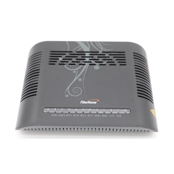
Page 12: Equipment Housing Description
2 Equipment Housing Description 2.1 Appearance The AN5506-04-B has a streamline design with novel and fashionable appearance. The LED indicators on the front panel show the operating status of the equipment, thereby the users can learn about the status directly. -
Page 13: Indicator Led Description
2 Equipment Housing Description 2.2 Indicator LED Description The AN5506-04-B shows the operating status of the equipment with various indicator LEDs, thereby the users can learn about the status directly. Table 2.1 shows the description of the indicator LEDs. Table 2.1 Indicator LED description for the AN5506-04-B... - Page 14 2 Equipment Housing Description Name Meaning Color Status Description softswitch system successfully. The equipment does not register to the softswitch system. The user picks up the telephone or the user is in a call. Phone1 Telephone The user hooks on interface Green user...
-
Page 15: Interface And Button Description
2.3 Interface and Button Description With all interfaces and buttons distributed on the rear panel, the AN5506-04-B has a simple model and is convenient for use. As shown in Figure 2.2, the interfaces and buttons from left to right are: power switch, power interface, telephone interfaces (×2), Ethernet... - Page 16 2 Equipment Housing Description Button Meaning Type Description Interface interface computer, router, etc. Connects to the optical SC / PC interface splitter.
-
Page 17: Product Installation
The installation position provides good earth grounding conditions. 3.2 Equipment Mounting The AN5506-04-B can be either secured on a stable plane like an office desk, or hung vertically against the wall. The two mounting methods are introduced below:... - Page 18 According to the recesses distance of the AN5506-04-B, drive the two mount-to-wall screws into the wall. Step 2 Align the recesses on the bottom of the AN5506-04-B with the screws on the wall and fix them up gently. Step 3 Take your hands off the AN5506-04-B slowly and make sure the equipment is mounted on the wall with the support of the screws.
-
Page 19: Cable And Wire Connection
3 Product Installation 3.3 Cable and Wire Connection 3.3.1 Connecting Optical Fiber Jumper Cable introduction The GPON interface of the AN5506-04-B can be uplinked to the central office end OLT equipment via the optical fiber. Connection procedure Step 1 Plan the layout of the optical fiber jumper. Measure the distance... - Page 20 The optical fiber jumpers should be arranged last to prevent them from being kinked, bent excessively or pressed. Connecting diagram Figure 3.1 Connection diagram for the optical fiber of the AN5506-04-B...
-
Page 21: Connecting Network Cable
Connection procedure Step 1 Plan the layout of the network cable. Measure the distance from the LAN interface of the AN5506-04-B to the user terminal and choose the network cable with an appropriate length for connection. Step 2 Secure the network cable and make the RJ-45 crystal head connectors at both ends of the cable. -
Page 22: Connecting Twisted-Pair Cable
Connection procedure Step 1 Plan the layout of the twisted-pair cable. Measure the distance from the Phone interface of the AN5506-04-B to the subscriber telephone and choose the twisted-pair cable with an appropriate length for connection. Step 2 Secure the twisted-pair cable and make the RJ-11 crystal head connectors at both ends of the cable. -
Page 23: Connecting Power Cable
Figure 3.3 Connection diagram for the twisted-pair cable of the AN5506-04-B 3.3.4 Connecting Power Cable The AN5506-04-B is connected to the power supply via the 3-conductor power adapter. Connection procedure Step 1 Take out the 3-conductor DC power adapter provided in the AN5506-04-B package. -
Page 24: Inspection After Installation
3 Product Installation Connecting diagram Figure 3.4 Connection diagram for the power cable of the AN5506-04-B Note: This power adapter can convert 220V AC into 12V DC input to provide power supply for the AN5506-04-B. 3.4 Inspection after Installation After you have completed the wire and cable connection and... - Page 25 Otherwise, check whether the twisted-pair cable is correctly connected. Step 7 During operation of the equipment, ensure the ventilation to avoid abnormal events caused by overheating. When any abnormality occurs, contact the local office of FiberHome for replacement.
-
Page 26: Configuration Guide
4 Configuration Guide 4 Configuration Guide 4.1 Preparation before Configuration 4.1.1 User’s Computer Requirement Step 1 Make sure the computer has installed the Ethernet card. Step 2 Make sure the computer has installed the Web browser (version: Microsoft IE 5.0 or higher). Step 3 Make sure the computer has installed and enabled the TCP / IP. - Page 27 4 Configuration Guide Step 2 In the Network Connections window, right-click the Local Area Connection icon and select Properties from the shortcut menu. The Local Area Connection Properties dialog box appears. Step 3 In the Local Area Connection Properties dialog box, click Internet Protocol (TCP/IP) and then click the Properties button.
-
Page 28: Disabling Proxy Server
Select the Obtain an IP address automatically mode (recommended). Configure the static IP: The configured IP address should be in the same network segment as the AN5506-04-B. IP address: 192.168.1.X (X is a decimal integer between 2 and 253) ... -
Page 29: Logging In Web Configuration Gui
4.2 Logging in Web Configuration GUI Purpose Log in the Web configuration GUI to configure and manage the AN5506-04-B. Prerequisite The AN5506-04-B is correctly connected to the user’s computer. The user’s computer is normally started. The AN5506-04-B is normally started. - Page 30 Subnet mask: 255.255.255.0 Procedure Enter the user name and password to access the Web configuration GUI of the AN5506-04-B. Step 1 Enter http://192.168.1.1 in the address bar of the browser and press Enter. The user login dialog box appears.
-
Page 31: Web Gui Layout
After being verified, you can access the Web configuration GUI. 4.3 Web GUI Layout The Web configuration GUI of the AN5506-04-B mainly consists of the following four parts, as shown in Figure 4.1. Navigation bar: Click the link to access the corresponding configuration management page. -
Page 32: User Management
4 Configuration Guide Figure 4.1 Web configuration GUI 4.4 User Management Step 1 Select Management in the navigation bar. In the GUI that is opened, configure the user account and password of the AN5506-04-B. - Page 33 4 Configuration Guide Step 2 Click the Apply button to save the new password configuration. The next time you log in with this account, you should enter the new user name and new password. Table 4.2 lists the description for the configuration parameters. Table 4.2 Description of the user management configuration parameters Configuration Item Description...
-
Page 34: Configuring Internet Access Service
4 Configuration Guide 4.5 Configuring Internet Access Service Step 1 Select Network in the navigation bar and click BroadBand Settings in the link bar to open the configuration GUI for the Internet access service. Step 2 Configure the Internet access service parameters according to Table 4.3. - Page 35 4 Configuration Guide Configuration Item Description Secondary DNS Server: Enter the secondary server address provided by the ISP. If you select the DHCP mode, the equipment will automatically obtain the above parameters. User Name: Enter the user name provided by the ISP.
-
Page 36: Configuring Lan Service
Table 4.4 Description of the LAN service configuration parameters Configuration Item Description Enter the LAN-side IP address of the IP Address AN5506-04-B, which is 192.168.1.1 by default. Enter the LAN-side subnet mask of the Subnet Mask AN5506-04-B, which is 255.255.255.0 by default. - Page 37 IP address automatically via the DHCP server. Enable: Enables the DHCP server. The user terminal connected AN5506-04-B can obtain the private network IP address automatically via the DHCP server. The default setting is Enable. Server: Start IP Address: Enter the starting...
-
Page 38: Configuring Onu Authorization
4 Configuration Guide Configuration Item Description server of the DHCP. Default Gateway: Enter the default gateway IP address of the DHCP, which is 192.168.1.1. Disable: Disables the network address conversion function. The default setting is Disable. Enable: Enables the network address conversion function. - Page 39 4 Configuration Guide Table 4.5 Description of the ONU authorization configuration parameters Configuration Item Description This item is read-only. The authorization mode Auth Method is LOID. Enter the ONU logical ID (24 characters at logicID most). Enter the ONU logical password (12 characters logicPassword at most).
-
Page 40: Faqs
5 FAQs 5 FAQs All indicator LEDs are extinguished after power-on. Check whether the power cable is correctly connected; Check whether the power switch on the equipment’s rear panel is in the ON position. The equipment fails to work. If the equipment works abnormally, check whether the power is connected normally or the voltage is not within specifications;... - Page 41 5 FAQs Fail to log in the Web page. Check the network card configuration, browser version of the user’s computer; Check whether the IP address of the user’s computer is correctly configured.
- Page 44 FiberHome Telecommunication Technologies Co., Ltd. Tel: +86 27 8769 1549 Address: No. 5 Dongxin Rd., Hongshan Dist., Fax: +86 27 8769 1755 Wuhan, China Website: www.fiberhomegroup.com Zip code: 430073...
Need help?
Do you have a question about the AN5506-04-B and is the answer not in the manual?
Questions and answers