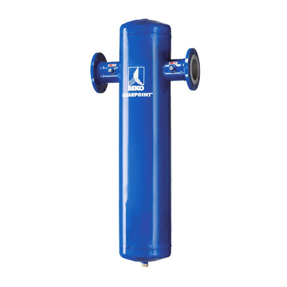
Beko CLEARPOINT Series Operating Manual
Filter with flanged connections
Hide thumbs
Also See for CLEARPOINT Series:
- Instructions for installation and operation manual (48 pages) ,
- Operating manual (10 pages)

Related Manuals for Beko CLEARPOINT Series


Summary of Contents for Beko CLEARPOINT Series
- Page 1 Operating Manual Filter with Flanged Connections ® CLEARPOINT Flange Filter Series models L100 to L304 READ MANUAL FIRST BEFORE INSTALLATION AND OPERATION...
-
Page 2: Table Of Contents
Table of Contents DEFINITION OF THE SAFETY SYMBOLS WARNINGS INTRODUCTION RECEIVING AND TRANSPORTING SAFETY RULES AREAS OF APPLICATION FUNCTION ECONOMIC EFFICIENCY OF FILTERS TECHNICAL SPECIFICATIONS OVERVIEW CORRECTION FACTORS DIMENSIONS INSTALLATION SITE POSITIONING INSTALLATION CHECKS AND MAINTENANCE FILTER ELEMENT REPLACEMENT BOLT TORQUE TABLE (FT-LBS) BOLT MARKING REFERENCE BOLT PATTERN REFERENCE BOLT PATTERN REFERENCE (con’t) -
Page 3: Definition Of The Safety Symbols
DEFINITION OF THE SAFETY SYMBOLS Before attempting any Electrical Hazard: General Warning: Warning: Warning: Warning: service, please read the Possibility of Risk of damage or injury Under pressure High temperature Non-breathable air manual electrocution Warning: Warning: Warning: Warning: Warning: Operations that can be Do not operate if parts Hearing All work to be... -
Page 4: Introduction
BEKO TECHNOLOGIES reserves the right to implement changes at any time, while retaining the essential features of the CLEARPOINT® filter, if such changes become necessary to enhance the technical capacity of the unit for reasons of safety or standard commercial practice. -
Page 5: Receiving And Transporting
RECEIVING AND TRANSPORTING filters undergo stringent quality control procedures in the manufacturing plant and are handed CLEARPOINT® over to the forwarding agent in perfect condition. Upon arrival of the goods, please check for any visible damage and, where appropriate, insist on a corresponding note on the delivery receipt. Contact the forwarding agent and arrange for an assessment of the damage. -
Page 6: Areas Of Application
• CLEARPOINT® filters, including accessories, must be checked once a week. This applies in particular to the function of the drain. Please refer to page 10 check list. AREAS OF APPLICATION CLEARPOINT® filters are designed for the separation of solid particles, aerosols, oil vapors and orders from non- aggressive compressed air or industrial gases. -
Page 7: Technical Specifications Overview
The nominal diameter of the pipes should be as uniform as possible in order to avoid creating additional flow resistance. Reduced pipe sections should only be installed where required for partial-flow outlets (ring, connecting or supply lines). TECHNICAL SPECIFICATIONS OVERVIEW Model Pipe Size Flow... -
Page 8: Dimensions
DIMENSIONS Component list 1. Flange Handles 2. ANSI 150# Flanged Connection 3. Differential Pressure Gauge 4. ASME Data Plate 5. BEKOMAT Zero Loss Concensate Drain CLEARPOINT® Flanged L100-L304_us_en_2014-6 (rev. A) -
Page 9: Installation Site
INSTALLATION SITE Serious consideration should be given when selecting the installation site for the filter, as an improper location could directly affect the proper operation of the filter. This unit is not suitable for use in explosive atmospheres, where risk of fire could exist, in the presence of gaseous or solid pollutants or in outdoor applications or areas exposed to the elements. -
Page 10: Checks And Maintenance
Pre-filter, and depth filters are supplied with an electronically level-controlled condensate drain, type BEKOMAT®, as standard. Please observe the instructions in the corresponding documentation. DO NOT DISPOSE OF THE CONDENSATE INTO THE ENVIRONMENT The condensate collected in the filter contains oil particles released into the air stream by the compressor. Dispose the condensate in compliance with all local, state and Federal rules and regulations. -
Page 11: Filter Element Replacement
FILTER ELEMENT REPLACEMENT • Where appropriated, close shutoff valves at gas inlet and outlet • Depressurize the housing, this can be accomplished by pushing the test button on the BEKOMAT® drain installed on the bottom port. • Unbolt top lid. You can use the last flange screw as a pivot. The lid is then simply turned aside to provide full access. -
Page 12: Bolt Torque Table (Ft-Lbs)
• Bubble check all fittings for leaks. • Make a note of the date for the next element replacement on the housing, the maintenance schedule and the label supplied with the elements. Stick the label on a part of the filter housing where it can easily be seen. Re- order new elements and, service kit for the automatic drain to ensure an adequate stock of spare parts. -
Page 13: Bolt Pattern Reference
BOLT PATTERN REFERENCE BOLT PATTERN REFERENCE (con’t) CLEARPOINT® Flanged L100-L304_us_en_2014-6 (rev. A) -
Page 14: Accessories
ACCESSORIES Differential-pressure gauge Differential-pressure gauges are used to determine the condition, i.e. the degree of fouling, of the filter elements. The scaling on the display field also allows an energy cost analysis. The FDPS differential-pressure gauge has two pressure chambers which are separated by a membrane. One chamber relates to the pressure upstream, the other one to the pressure downstream of the filter element. -
Page 15: Spare Parts
SPARE PARTS Model Order BEKOMAT BEKOMAT Quantity Service unit Drain 25 µm 5 µm 1 µm 0.01 0.003 Gaskets µm Filter elements L100 4032958 4023573 4025091 L102 4023573 4025091 4032959 L150 4023573 4025091 4032959 4023573 4025091 L156 4032960 L200 4023573 4025091 4032961 L204... -
Page 16: For Technical Product Support Please Call +1 (800) 235-6797 And Select Option 2
For technical product support please call +1 (800) 235-6797 and select Option 2 CLEARPOINT® Flanged L100-L304_us_en_2014-6 (rev. A)