Advertisement
Quick Links
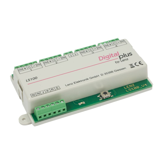
Accessory Decoder LS 100/110
Accessory decoders are the link between your NMRA DCC
system and your function devices (that is turnouts, signals,
uncouplers, etc.) on your model train layout.
Accessory decoders receive commands sent from the command
station via the power station and activate the drives of turnouts
or other switching devices. For DIGITAL plus systems these
switching commands are activated from input devices, such as,
hand held controller LH100, tower cab LW100, interface LI100 or
translation
compatible digital system).
+Dimensions: approximately 3.5 x 3.5" (90 x 90 mm)
LS100/110
Accessory DCC Decoder
Art. Nr. 11100 / 11110
January 1999
upgraded version 2.2
module
LC100
(in
connection
Submitted for NMRA
Conformance testing
DIGITAL plus
1
with
another,
Advertisement

Related Manuals for Lenz Digital plus LS100


Summary of Contents for Lenz Digital plus LS100
- Page 1 Accessory Decoder LS 100/110 Accessory decoders are the link between your NMRA DCC system and your function devices (that is turnouts, signals, uncouplers, etc.) on your model train layout. Accessory decoders receive commands sent from the command station via the power station and activate the drives of turnouts or other switching devices.
- Page 2 Accessory Decoder LS 100/110 Whats new in the upgraded LS100/110? A push button and an LED have been added to the LS100/110 to make programming easier. Direct CV mode is now supported in service mode and a selectable flashing rate has been added.
- Page 3 Accessory Decoder LS 100/110 Specifications of LS100/LS110 Up to 4 function devices each with a twin output can be connected to each LS100/LS110. Power for these function devices can by supplied by the track power or through an external power supply. Each function device output can have its characteristics individually set (by programming).
- Page 4 Accessory Decoder LS 100/110 pulse duration a new switching command is received by the LS100/110, the output remains active for another pulse duration. Constant output: By pressing the ‘+’ key on the LH100, the function device output + is activated and remains active until the ‘-’ key is pressed at which time the - output is activated.
- Page 5 Accessory Decoder LS 100/110 Installing the accessory decoder LS100/LS110 Connecting the LS100/LS110 to a power station and/or separate power supply line Before you connect your LS100/LS110 to your NMRA DCC system or the power supply line, you must turn off your DCC system and disconnect the power supply (unplug the transformer from wall outlet).
- Page 6 Accessory Decoder LS 100/110 DCC system and does not use a separate power supply line to power the LS100/110. The second option uses an external power supply to power the LS100/110. Illustrations 1 and 2 show the connection using the LS110. The LS100 is connected in the same way, using the same terminals.
- Page 7 Accessory Decoder LS 100/110 Illustration 3: Connecting the feedback bus on LS100 DIGITAL plus...
- Page 8 Accessory Decoder LS 100/110 connected to the corresponding terminals on a power station LV100/LV101. Terminals ‘ ≈ ≈ ‘ are connected to a transformer with 16V AC. Connecting the LS100 to the feedback bus of LZ100 (LS110 only) Terminals R and S are connected to the corresponding terminals on command station LZ100.
- Page 9 Accessory Decoder LS 100/110 In the following table the common wire colors from some track manufacturers, is matched to the wire numbers in Illustration 4. Wire #: ROCO black green Arnold blue grey purple Fleischmann beige black brown Trix yellow black green Märklin blue...
- Page 10 Accessory Decoder LS 100/110 Illustration 4: Connecting devices to the LS100/LS110 function outputs...
- Page 11 Accessory Decoder LS 100/110 Connecting a motorized turnout drive To connect motorized turnout drives, you need adapter LA010 (Illustration 4 lower right). This adapter changes the polarity of the motor connections to the required direction as needed. By using this adaptor, you avoid complicated relay set-ups for controlling a motorized drive.
- Page 12 Accessory Decoder LS 100/110 For information on how to read the turnout position on hand held controller LH100 or another device, please refer to the manual for that device. Using external control on conjunction with the LS100/110 The LS100/LS110 version 2 provides the ability to control the function devices connected to LS100/LS110 either digitally or with an external push button (or REED switch).
- Page 13 Accessory Decoder LS 100/110 It is required that the output to be optionally controlled by an external push button not be set to flashing or constant operation and that the function device being controlled is equipped with end-of-stroke disconnect. Shown is the typical twin-coil drive for signals or turnouts. The two coils are connected with the + and - terminals on the accessory decoder.
- Page 14 Accessory Decoder LS 100/110 The shared address area of LS100/LS110/LS120 and LR100 Information about the positions of turnouts and signals from accessory decoder LS100/LS110 and feedback encoder LR100 occupies the same memory locations in the command station. Information from the feedback encoder with addresses 1 to 63 overlaps information from turnouts 1 to 256.
- Page 15 Accessory Decoder LS 100/110 Press the programming button on the LS100/LS110 and keep it pressed until the LED lights up and stays lit (this takes a few seconds). Now release the button. The LED stays on. The LS100/LS110 now will take its new address from the first DCC accessory decoder command it receives.
- Page 16 Accessory Decoder LS 100/110 Programming address settings through programming output of LZ100 Address and other settings of LS100/LS110 are stored in so called “registers”, abbreviated “R”. These registers can be imagined as a sort of notepad that can have new entries put on them again and again.
- Page 17 Table 4: Setting the flashing rate The decoder version number is contained in R7. R8 contains the manufacturer ID, which for Lenz Elektronik is 99. Both registers can only be read, and can not be overwritten. Connecting the LS100/LS110 to the programming output of...
- Page 18 Accessory Decoder LS 100/110 Illustration 7: Connecting LS100/LS110 to the programming output of LZ100 To program address and settings you need your command station LZ100, hand held controller LH100 and a transformer with 16V AC output to supply power for LZ100. The LS100/LS110 is programmed using the programming output of command station LZ100.
- Page 19 Note: There is an error in the LH100 to be aware of If you select the “CV” mode, the LH100 starts an address search . At its completion, you receive the display "LENZ -d". After pressing any key the address is displayed “SAD xx”, where xx is the decoders address.
- Page 20 Accessory Decoder LS 100/110 “ERR 02”. Ignore this message, since LS100/LS110 is not able to confirm successful programming to the command station. Neither can you read out the values stored in the memory locations. Programming the settings of an output In the following examples the settings of output 1 of LS100/LS110 are programmed.
- Page 21 Accessory Decoder LS 100/110 Table 5 Feedback addresses / turnout addresses: F-Feedback address; T-Turnout address, FE- Feedback information in the command station 1 to 8 1 to 4 257 to 264 129 to 132 9 to 16 5 to 8 265 to 272 133 to 136 17 to 24...
-
Page 22: Troubleshooting
Accessory Decoder LS 100/110 Trouble shooting Problem Cause Solution Turnout does not throw, the Wrong turnout address Enter correct turnout LED does not flicker while a entered. address. switching command is being Connection between command Check correct sent (a switching command is station and power station or connections. - Page 23 Accessory Decoder LS 100/110 Lenz GmbH does everything it can do to ensure that its products are free from defects and will operate for the life of your model railroad equipment. From time to time even the best engineered products fail either due to a faulty part or from accidental mistakes in installation.
- Page 24 Accessory Decoder LS 100/110 Please contact your dealer or authorized Lenz GmbH warranty center for specific instructions and current service charges prior to returning any equipment for repair. Hüttenbergstraße 29 Lenz Agency of North America 35398 Gießen, Germany PO Box 143...
Need help?
Do you have a question about the Digital plus LS100 and is the answer not in the manual?
Questions and answers