
Related Manuals for Eding CNC CNC760

Summary of Contents for Eding CNC CNC760
- Page 1 Hardware Manual CNC760 Axis Breakout Board Revision 1 1 March, 2021 Draft Copyright © 2021 by Eding CNC...
- Page 2 Hardware Manual – CNC760 Axis Breakout Board History: Revision Date Author 1-3-2021 Revision overview: Revision Remarks Initial version. Page | 2...
-
Page 3: Table Of Contents
Hardware Manual – CNC760 Axis Breakout Board Table of contents Introduction ............................ 4 Purpose ........................... 4 Scope ............................4 Board overview ..........................5 Mounting the breakout board ......................6 Pinning of the breakout board ......................8 Page | 3... -
Page 4: Introduction
Hardware Manual – CNC760 Axis Breakout Board 1 Introduction 1.1 Purpose This manual describes the hardware of the CNC760 Axis Breakout. The CNC760 Axis Breakout makes it easier to connect wires to the CNC760 Axis output. 1.2 Scope This document describes the hardware of the CNC760 Axis Breakout Board. More information about the different signals can be found in the Hardware Manual if the CNC760. -
Page 5: Board Overview
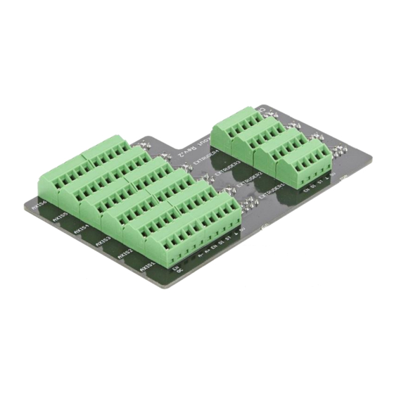
Please note, the 4 extruder output all use the step and direction signal from of axis 6. Please check the hardware manual of the CNC760 for more info about this. Figure 1. Top view CNC760 Axis Breakout board. -
Page 6: Mounting The Breakout Board
The breakout board is mounted on top of the CNC760. Figure 2. CNC760 Axis Breakout Board mounted on top CNC760. Mounting the board is done in three steps: Step 1: Align the axis breakout board with the connector on the CNC760. Figure 3. Aligning both boards. Page | 6... - Page 7 Hardware Manual – CNC760 Axis Breakout Board Step 2: Let the board come down so all pins will be automatically aligned. Figure 4. Both boards completly aligned. Step 3: Press down on the axis breakout board to make both boards connect. Make sure the breakout board is equally pressed down everywhere.
-
Page 8: Pinning Of The Breakout Board
4 Pinning of the breakout board The board connects to the connectors of the CNC760. In this chapter the exact pinning between those is described. For more detailed information about each signal at its usage please have a look at the ‘CNC760 hardware manual’. - Page 9 Hardware Manual – CNC760 Axis Breakout Board In the table below the extruder connections Electrical CNC760 Pin # Name Direction Type Function Remarks Spec. Connector pin DIGITAL AUX7-AUX10 DIGITAL Direction signal This is axis 6 signal DIGITAL Step signal This is axis 6 signal...
Need help?
Do you have a question about the CNC760 and is the answer not in the manual?
Questions and answers