
Related Manuals for Iskra MT 511


Summary of Contents for Iskra MT 511
- Page 1 Measuring transducers: Power Transducer & Recorder MT 511/UMT 511 Power Transducer MT 510/UMT 510 Voltage Transducer MT 516/UMT 516 Current Transducer MT 518/UMT 518 April 2019 • Version 6.01 User’s Manual...
- Page 2 Power Transducer & Recorder MT 511/UMT 511 Power Transducer MT 510/UMT 510 Voltage Transducer MT 516/UMT 516 Current Transducer MT 518/UMT 518 User and Installation manual User’s Manual...
- Page 3 MT 510, UMT 510, MT 511, UMT 511, UMT 516, UMT 516 and UMT 518, UMT 518. This chapter deals with important information and warnings that should be considered for safe installation and handling with a device in order to assure its correct use and continuous operation.
- Page 4 Used symbols on devices’ housing and labels SYMBOL EXPLANATION WARNING Indicates situations where careful reading of this manual is required and following requested steps to avoid potential injury is advised. Double insulation in compliance with the SIST EN 61010−1 standard. Protective conductor terminal.
- Page 5 ASIC DESCRIPTION AND OPERATION Table of contents BASIC DESCRIPTION AND OPERATION NTRODUCTION ESCRIPTION OF THE DEVICE URPOSE AND USE OF DIFFERENT TYPES OF MEASURING TRANSDUCERS YPE DIFFERENCES CONNECTION NTRODUCTION OUNTING LECTRICAL CONNECTION ONNECTION OF INPUT OUTPUT MODULES OMMUNICATION CONNECTION ...
- Page 6 ASIC DESCRIPTION AND OPERATION TECHNICAL DATA CCURACY ECHANICAL CHARACTERISTICS OF INPUT LECTRICAL CHARACTERISTICS OF INPUT MODULES NALOGUE OUTPUT OMMUNICATION LECTRONIC FEATURES AFETY FEATURES IMENSIONS ABBREVIATION/GLOSSARY APPENDICES APPENDIX A: MODBUS COMMUNICATION PROTOCOL APPENDIX C: CALCULATIONS & EQUATIONS User’s Manual...
- Page 7 ASIC DESCRIPTION AND OPERATION 1 BASIC DESCRIPTION AND OPERATION The following chapter presents basic information about multifunction transducers required to understand its purpose, applicability and basic features connected to its operation. In this chapter you will find: NTRODUCTION ESCRIPTION OF THE DEVICE URPOSE AND USE OF DIFFERENT TYPES OF MEASURING TRANSDUCERS YPE DIFFERENCES User’s Manual...
- Page 8 − Function completely supported Each of the three positions, where the symbols are indicates a Measuring transducer type. Positions follow from left to right: (U)MT 511/(U)MT 510/(U)MT 516/(U)MT 518 Subchapter Symbols next to the subchapters indicate accessibility of functions described. Accessibility of functions is indicated with the following symbols: −...
- Page 9 ASIC DESCRIPTION AND OPERATION Description of the device Measuring transducer is intended for measuring, analyzing and monitoring single-phase electrical power network. It measures true RMS values by means of fast sampling of voltage and current signals, which makes instrument suitable for acquisition of transient events. A built-in microcontroller calculates measurements (voltage, current, frequency, energy, power, power factor, THD, phase angles, MD) from the measured signals.
- Page 10 1.2.4 Power transducer & recorder MT 511/UMT 511 (U)MT 511 measures all parameters like (U)MT 510 and additionally it records the readings and alarms in the internal memory for the period of three years or more. Internal battery powered real time clock enables also energy measurement as well as recording of time –...
- Page 11 ASIC DESCRIPTION AND OPERATION Type differences Different types differ on functionality and equipment as shown in the following table. Differences in hardware Feature MT 511 MT 510 MT 516 MT 518 UMT 511 UMT 510 UMT 516 UMT 518 Internal flash memory ×...
- Page 12 Only a qualified person shall therefore perform connection. Iskra Sistemi does not take any responsibility regarding the use and connection. If any doubt occurs regarding connection and use in the system, which device is intended for, please contact a person who is responsible for such installations.
- Page 13 CONNECTION Introduction Before use: Check voltages, supply voltage and nominal frequency. Check protective fuse rating (the recommended maximum rating of the external protective fuse for this equipment is 6 A - Red Spot type or equivalent). WARNING! Wrong or incomplete connection of voltage, protective ground or other terminals can cause malfunction or damage the device.
- Page 14 CONNECTION Electrical connection Voltage inputs of measuring transducer can be connected directly to low-voltage network or via appropriate voltage measuring transformer to medium or high voltage network. Current inputs of measuring transducer can be connected directly to low-voltage network or via a corresponding current transformer.
- Page 15 CONNECTION Connection of input/output modules WARNING! Check the module features that are specified on the label, before connecting module contacts. Wrong connection can cause damage or destruction of module and/or device. Connect module contacts as specified on the label. Examples of labels are given below and describe modules built in the device.
- Page 16 CONNECTION Communication connection (U)MT51x has a wide variety of communication possibilities to suit specific demands. In the case of simultaneous use of Ethernet and USB communication, the standard port (COM1) is shared by two communication channels: COM1A (Ethernet) and COM1B (USB). This allows different users to access data from (U)MT51x simultaneously and by using Ethernet communication, data can be accessed worldwide.
- Page 17 The driver is provided on the CD, enclosed in the original shipment package, or can be downloaded from the Iskra d.o.o. web page https://www.iskra.eu/en/. With this driver installed, USB is redirected to a serial port, which should be selected when using MiQen software.
- Page 18 CONNECTION Survey of communication connection Connector Terminals Position Data direction Description Not connected − From Data transmission (Tx) Data reception (Rx) Not connected − Grounding () RS232 − Not connected − − Do not connect! − Do not connect! Not connected − Not connected −...
- Page 19 CONNECTION Connection of auxiliary power supply Measuring transducer has universal (AC/DC) auxiliary power supply. Information on electric consumption is given in chapter Technical data. Auxiliary supply is connected through three screw-in connectors. It can be either LOW (19 VDC – 70 VDC; 48 VAC – 77 VAC) or HIGH (70 VDC – 300 VDC; 80 VAC –...
-
Page 20: Table Of Contents
SETTINGS 3 SETTINGS A setting structure, which is similar to a file structure in an explorer is displayed in the left part of the MiQen setting window. Available settings of that segment are displayed in the right part by clicking any of the stated parameters. -
Page 21: Introduction
PC. MiQen software MiQen software is a tool for a complete programming and monitoring of ISKRA measuring instruments, connected to a PC via serial communication or by a special WM-USB adapter. A user-friendly interface consists of five segments: devices management (Connection), instrument settings (Settings), real-time measurements (Measurements), data analysis (Analysis), and software upgrading (Upgrades). - Page 22 MiQen version 2.1 or higher is required for programming and monitoring Multifunction tranduscers. Software installation is stored on a CD as a part of consignment or it can be downloaded from https://www.iskra.eu/en/Iskra-Software/MiQen-Settings-Studio/ PLEASE NOTE MiQen has very intuitive help system. All functions and settings are described in Info window on the bottom of MiQen window.
-
Page 23: Setting Procedure
3.5.3 Date and time Set date and time of the meter. Setting is important for correct memory operation, maximal values (MD), etc (MT 511 / UMT 511 only). 3.5.4 Maximum demand calculation (MD mode) The instrument provides maximum demand values from a thermal function demand values. -
Page 24: Connection
SETTINGS 3.5.5 Starting current for PF and PA (mA) At all measuring inputs noise is usually present. It is constant and its influence on the accuracy is increased by decreasing measuring signals. It is present also when measuring signals are not connected and it occurs at all further calculations as very sporadic measurements. -
Page 25: Serial Communication (Com1)
(depending on a serial number of the meter). The BP password is available in the user support department in ISKRA D.O.O., and is entered instead of the password PL1 or/and PL2. Do not forget to state the meter serial meter when contacting the personnel in Iskra d.o.o.. - Page 26 SETTINGS 3.8.1 Password setting A password consists of four letters taken from the British alphabet from A to Z. When setting a password, only the letter being set is visible while the others are covered with *. Two passwords (PL1, PL2) and the time of automatic activation could be set. Password modification A password can be modified;...
-
Page 27: Energy
SETTINGS Energy WARNING! After modification of energy parameters, the energy meters must be reset otherwise all further energy measurements could be incorrect. 3.9.1 Common energy exponent Common energy exponent defines minimal energy that can be displayed on the energy counter. On the −3 basis of this and a counter divider, a basic calculation prefix for energy is defined (−3 is 10 Wh = mWh,... -
Page 28: Inputs And Outputs
SETTINGS Inputs and outputs Module settings depend on built-in modules. 3.10.1 Analogue output module Each of up to four analogue outputs is fully programmable and can be set to any of 6 ranges. Output parameter Set the measured parameter to be transformed onto the analogue output. Output range Defines analogue output full-scale ranges: DC current output... - Page 29 SETTINGS Example of settings with linear and bent characteristic: Average interval for analogue output Defines the average interval for measurements on the analogue output. Available settings are from 1 period (0.02 sec by 50 Hz) up to 256 periods (5.12 sec by 50 Hz). 3.10.2 Alarm/Digital output module Alarm groups that are connected with an alarm module and a signal shape are defined.
- Page 30 SETTINGS 3.10.3 Pulse output module A corresponding energy counter can be assigned to a pulse output. A number of pulses per energy unit, pulse length, and a tariff in which output is active are set. WARNING! Pulse parameters are defined by SIST EN 62053−31 standard. In chapter Calculation of recommended pulse parameters, below a simplified rule is described to assist you in setting the pulse output parameters.
-
Page 31: Alarms
SETTINGS Alarms Alarms are used for alarming exceeded set values of the measured quantities. − (U)MT 510/516/518 do not support alarms recording into memory 3.11.1 Alarms setting Measuring transducer supports recording and storing of 16 alarms in 2 groups. For each group of alarms a delay time and alarm deactivation hysteresis can be defined. -
Page 32: Memory
Memory Measurements, alarms, reports and details of supply voltage quality are stored in a built in memory in the (U)MT 511 - 8MB flash. All records stored in memory are accessible via communication with MiQen software. − (U)MT 510/516/518 have no memory 3.12.1 Memory division... - Page 33 MEASUREMENTS 4 MEASUREMENTS In the following chapters the device operation is explained more in detail. UPPORTED MEASUREMENTS XPLANATION OF BASIC CONCEPTS ALCULATION AND DISPLAY OF MEASUREMENTS RESENT VALUES LARMS User’s Manual...
-
Page 34: Measurements
MEASUREMENTS Supported measurements Measurements support regarding the device type is described in chapter Type differences, page 5. Selection of supported measurements of individual instrument type is changed with the connection settings. All supported measurements could be read via communication (MiQen). Explanation of basic concepts 4.3.1 Sample factor −... -
Page 35: Calculation And Display Of Measurements
MEASUREMENTS Calculation and display of measurements This chapter deals with capture, calculation and display of all supported quantities of measurement. Only the most important equations are described; however, all of them are shown in chapter Equations with additional descriptions and explanations. ... -
Page 36: Alarms
MEASUREMENTS 4.6.6 Energy Four individual counters of energy measurements are available. 4.6.7 MD values Measurements of MD values. 4.6.8 THD − Total harmonic distortion THD is calculated for phase currents, phase voltages and is expressed as percent of high harmonic components relative to first harmonic. - Page 37 It is recommended that the instrument is sent back in the factory for battery replacement. Although it is possible that replacement is made by the qualified person, but in this case Iskra d.o.o. does not take on responsibility for any injuries, dysfunction of the instrument or mechanical damage.
- Page 38 TECHNICAL DATA 6 TECHNICAL DATA In following chapter all technical data regarding operation of multifunction transducers is presented. CCURACY ECHANICAL CHARACTERISTICS OF INPUT LECTRICAL CHARACTERISTICS OF INPUT MODULES NALOGUE OUTPUT OMMUNICATION LECTRONIC FEATURES ...
-
Page 39: Technical Data
TECHNICAL DATA Accuracy Total accuracy (measurements and analogue output) according to IEC/EN 60 688 is presented as percentage of reading of the measurement except when it is stated as an absolute value. Measured values Range Accuracy class Rms current I 0.2 (0.1) Maximum current 12.5 A... -
Page 40: Mechanical Characteristics Of Input
TECHNICAL DATA Mechanical characteristics of input 6.2.1 Permitted conductor cross-sections Terminals Max. conductor cross-sections DIN / ANSI housing Voltage inputs (2) 0.325 mm … 2.5 mm (22 – 14 AWG) one conductor Current inputs (2) 0.325 mm … 2.5 mm (22 –... -
Page 41: I/Omodules
TECHNICAL DATA I/O modules Alarm/Digital/ Watchdog output module Type Relay switch Rated voltage 48 V AC/DC (+40% max) Max. switching current 200 mA Contact resistance ≤ 100 mΩ (100 mA, 24V) Impulse Max. 4000 imp/hour Min. length 100 ms Signal shape Normal Until the condition is fulfilled... -
Page 42: Communication
Battery Manufacturer Varta Type CR2032 Li-battery Battery lifetime Approx. 6 years (at 23°C − typical) Memory (U)MT 511 Capacity 8 MB Recorder A Divisions Recorder B Alarms recorder Sampling period 1 min to 60 min Status LED’s... -
Page 43: Safety Features
TECHNICAL DATA Safety features Protection Protection class I (protective earth terminal due to touchable metal parts (USB-B, RJ-45, DB9), current limiting fuse 1 A on aux. Supply (L terminal) Voltage inputs via high impedance Double insulation on I/O ports and COM1-2 ports Pollution degree Installation category CAT III;... -
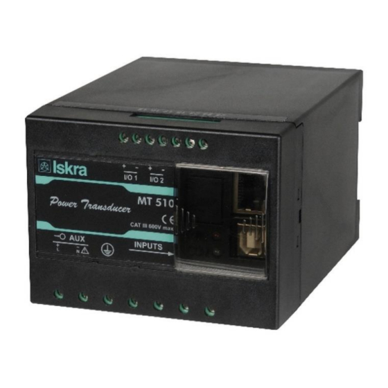
Page 44: Dimensions
TECHNICAL DATA Dimensions Construction Appearance Measuring transducers MT51x (standard EU clamp style terminals): UMT51x (ring type terminal block): User’s Manual... - Page 45 Abbreviations are explained within the text where they appear the first time. Most common abbreviations and expressions are explained in the following table: Term Explanation MODBUS / DNP3 Industrial protocol for data transmission MiQen Setting Software for ISKRA instruments Pulse input module Alternating quantity Infrared (optical) communication Pt1000 Temperature sensor Root Mean Square...
- Page 46 APPENDICES 8 APPENDICES APPENDIX A: MODBUS communication protocol Modbus and DNP3 protocol are enabled via RS232 and RS485 or Ethernet communication. 8.1.1 Modbus There are two Modbus protocol types: Modbus RTU for serial communication and Modbus TCP for Ethernet communication. Modbus protocol enables operation of device on Modbus networks.
- Page 47 APPENDICES MODBUS Parameter Register Type Start Demand values Dynamic demand values 34302 34303 34304 34305 Apparent Power (Sn) 34306 34307 Active Power (Pn) - (positive) 34308 34309 Active Power (Pn) - (negative) 34310 34311 Reactive Power (Qn) - L 34312 34313 Reactive Power (Qn) - C 34314...
- Page 48 APPENDICES MODBUS Parameter Register Start Type 34424 34425 Energy Energy Counter 1 34426 Energy Counter 2 34427 Energy Counter 3 34428 Energy Counter 4 34429 Internal Temperature 34430 FAST RESPONSE normalized actual measurements 34501 34502 Active Power (P1) 34503 Reactive Power (Q1) 34504 Apparent Power (S1) 34505...
- Page 49 APPENDICES MODBUS Parameter Register Start Type Reactive Power (Qn) - C 34643 34644 T_float Apparent Power (Sn) 34645 34646 T_float 34647 34648 T_float 34649 34650 T_float Energy Energy Counter 1 34651 34652 T_float Energy Counter 2 34653 34654 T_float Energy Counter 3 34655 34656 T_float...
- Page 50 APPENDICES MODBUS Parameter 100% value Register Type Energy Energy Counter 1 34426 Energy Counter 2 34427 Actual counter value MOD Energy Counter 3 34428 20000 is returned Energy Counter 4 34429 Internal Temperature 34430 100° FAST RESPONSE normalized actual measurements 34501 34502 Active Power (P1)
- Page 51 APPENDICES Register table for the basic settings Register Content Type Values / Dependencies P. Level CT Secondary 40144 CT Primary 40145 A/10 40146 VT Secondary 40147 VT Primary V/10 Current input range (%) 40148 10000 for 100% 5.00 200.00 Voltage input range (%) 40149 10000 for 100% 2.50...
- Page 52 APPENDICES Signed Value (16 bit), 2 decimal places Example: -123.45 = CFC7(16) T_Str4 Text: 4 characters (2 characters for 16 bit register) T_Str6 Text: 6 characters (2 characters for 16 bit register) T_Str8 Text: 8 characters (2 characters for 16 bit register) T_Str16 Text: 16 characters (2 characters for 16 bit register) T_Str40...
- Page 53 APPENDICES APPENDIX C: CALCULATIONS & EQUATIONS Calculations Definitions of symbols Symbol Definition Sample factor Average interval Phase voltage (U or U Total number of samples in a period Sample number (0 ≤ n ≤ N) Current sample n Phase voltage sample n φ...
- Page 54 APPENDICES EQUATIONS Voltage Phase voltage N − samples in one period (up to 65 Hz) ∑ = √ N − samples in M periods (above 65Hz) Example: 400 Hz → M Current Phase current N − 128 samples in a period (up to 65 Hz) ∑...
- Page 55 APPENDICES Current THD �� √ ∑ ���� ��=2 − value of first harmonic �� ������ ( % ) = �� n − number of harmonic Voltage THD �� √ ∑ ���� ��=2 − value of first harmonic �� ������ ( % ) = ��...
- Page 56 Published by Iskra, d.o.o. • Subject to change without notice • Version 6.01 April 2019 • EN K22.496.452...
Need help?
Do you have a question about the MT 511 and is the answer not in the manual?
Questions and answers