
Related Manuals for Grundfos BoosterpaQ Hydro MPC


Summary of Contents for Grundfos BoosterpaQ Hydro MPC
- Page 1 / service-commercial@motralec.com / 01.39.97.65.10 GRUNDFOS INSTRUCTIONS BoosterpaQ - Hydro MPC Installation and operating instructions...
- Page 2 Grundfos or an authorized service station for instructions. Any defective product to be returned to Grundfos or a service station must be sent freight prepaid; documentation supporting the warranty claim and/or a Return Material Authorization must be included if so instructed.
-
Page 3: Table Of Contents
Mechanical installation Electrical installation 2. Scope of these instructions Start-up These installation and operating instructions apply to Grundfos Control panel Hydro MPC booster sets. Display (pos. 1) Hydro MPC is a range of factory-assembled booster sets, ready Buttons and indicator lights for installation and operation. -
Page 4: Product Description
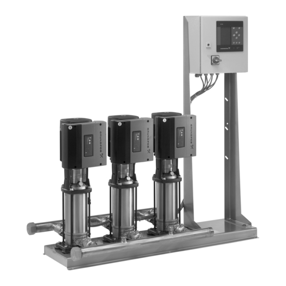
www.motralec.com / service-commercial@motralec.com / 01.39.97.65.10 3. Product description Hydro MPC booster sets are divided into seven groups based on control type: As standard, Hydro MPC booster sets consist of two to six pumps coupled in parallel and mounted on a common base frame with all Control Description the necessary fittings and a control cabinet. -
Page 5: Nameplate
www.motralec.com / service-commercial@motralec.com / 01.39.97.65.10 4. Nameplate The nameplate of the booster set is fitted on the base frame. Type: Model: Serial No.: Mains supply: Max. oper. press.: T Medium: ºF Q Max.: H Min.: Number HP Fixed speed pumps: E-pumps: Order No.: Options.:... -
Page 6: Software Label
Control MPC options - GSC file numbers Hydro MPC - GSC file number Hydro MPC options - GSC file numbers Pump data - GSC file numbers A .gsc (Grundfos Standard Configuration) file is a Note configuration data file. 6. Type key... -
Page 7: Examples Of Control Variants
www.motralec.com / service-commercial@motralec.com / 01.39.97.65.10 6.1 Examples of control variants Booster sets with motors that include an integrated frequency converter Hydro MPC-E Hydro MPC-ED Hydro MPC-ES Hydro MPC booster set with three CRE Hydro MPC booster set with two CRE pumps Hydro MPC booster set with one CRE pump pumps. - Page 8 www.motralec.com / service-commercial@motralec.com / 01.39.97.65.10 Booster sets with motors connected to external frequency converters Hydro MPC-EF Hydro MPC-EDF Hydro MPC-F Hydro MPC booster set with three CR Hydro MPC booster set with two CR Hydro MPC booster set with three CR pumps each connected to an external pumps connected to external frequency pumps connected to an external...
- Page 9 www.motralec.com / service-commercial@motralec.com / 01.39.97.65.10 Booster set with mains-operated pumps also called DOL (on/off) Hydro MPC-S Hydro MPC booster set with three mains-operated CR(I) pumps. One mains-operated CR pump in operation. Three mains-operated CR pumps in operation. • Hydro MPC-S maintains pressure range through cutting in/out the required number of pumps.
-
Page 10: Installation
www.motralec.com / service-commercial@motralec.com / 01.39.97.65.10 7. Installation All nuts should be checked and re-tightened if necessary prior to start-up. Warning The pipes must be fastened to parts of the building to ensure that they cannot move or be twisted. Installation and operation must comply with local regulations and accepted codes of good practice. -
Page 11: Electrical Installation
If the rotation is incorrect on any 3 phase pumps, switch any 2 during the pressurizing process. of the 3 power main wires supplied to the control panel (L1, L2, L3). If that doesn’t correct the rotation, call your Grundfos Prime the system as follows representative. - Page 12 www.motralec.com / service-commercial@motralec.com / 01.39.97.65.10 INSTALLATION AND STARTUP NOTES...
-
Page 13: Control Panel
www.motralec.com / service-commercial@motralec.com / 01.39.97.65.10 9. Control panel 9.1.1 Menu line The menu line (A) is illustrated in fig. 7. The control panel in the front cover of the control cabinet features a display, a number of buttons and two indicator lights. The The display has four main menus: control panel enables manual setting and change of setpoint. -
Page 14: Buttons And Indicator Lights
www.motralec.com / service-commercial@motralec.com / 01.39.97.65.10 9.2 Buttons and indicator lights The buttons (pos. 2 to 10) are active when they are illuminated. 9.2.1 Arrow to the right (pos. 2) Press the button to move to the next menu in the menu when the Settings menu is structure. -
Page 15: Functions
www.motralec.com / service-commercial@motralec.com / 01.39.97.65.10 10. Functions 10.1 Tree of functions Continued on page 16 1. Status 2. Operation 3. Alarm 1 Status 2 Operation 3 Alarm status 3. Current alarms 2. System operating mode 3. Current alarms 3.1. Current alarms 2. -
Page 16: Overview
www.motralec.com / service-commercial@motralec.com / 01.39.97.65.10 10.2 Overview Continued from page 15 4. Settings Primary controller 4.1.1 PI controller 4.1.2 Alternative setpoints 4.1.2.1...4.1.2. Alternative setpoints 2...7 4.1.3 Setpoint influence 4.1.3.1 External setpoint influence 4.1.3.1 Influence function 4.1.4 Primary sensor 4.1.5 Redundant primary sensor Pump cascade control 4.2.1 Min. - Page 17 www.motralec.com / service-commercial@motralec.com / 01.39.97.65.10 Section Display and display number See page 10.4 Status 10.4.1 Current alarms (3.1) 10.4.2 System status (1.2) 10.4.3 Operating mode (1.2.1) 10.4.4 Setpoint (1.2.2) 10.4.5 Setpoint influence (1.2.3) 10.4.6 Measured values (1.2.4) 10.4.7 Pump status (1.3 to 1.8) 10.5 Operation 10.5.1 Operation (2)
-
Page 18: Description Of Functions
www.motralec.com / service-commercial@motralec.com / 01.39.97.65.10 10.3 Description of functions 10.4.1 Current alarms (3.1) The description of functions is based on the four main menus of the CU 351 control unit: Status, Operation, Alarm and Settings. The functions apply to all control variants unless otherwise stated. - Page 19 www.motralec.com / service-commercial@motralec.com / 01.39.97.65.10 10.4.3 Operating mode (1.2.1) Example Operating modes Source Priority User- Stop Max. Min. Normal defined Fault External signal CU 351 The source Fault may for instance relate to the function dry- running protection. In case of water shortage, the operating mode will be Stop, as this mode has first priority.
-
Page 20: Operation
www.motralec.com / service-commercial@motralec.com / 01.39.97.65.10 10.4.5 Setpoint influence (1.2.3) 10.4.7 Pump status (1.3 to 1.8) Fig. 13 Setpoint influence Fig. 15 Pump status Description Description The selected setpoint can be influenced by parameters. The This display shows the operational state of the individual pumps. parameters, shown as percentage from 0 to 100%, can only The pumps may have different operating modes: reduce the setpoint, as the influence is multiplied with the... - Page 21 www.motralec.com / service-commercial@motralec.com / 01.39.97.65.10 10.5.1 Operation (2) 10.5.2 System operating mode (2.1) Fig. 16 Operation Fig. 17 System operating mode Description Description The column shows the setting range. In closed-loop control it Hydro MPC can be set to five different operating modes. Normal corresponds to the range of the primary sensor, here 0-16 bar.
- Page 22 www.motralec.com / service-commercial@motralec.com / 01.39.97.65.10 Description Example 3 There are two control modes, namely closed and open loop. The Tank typical control mode is closed loop where the built-in PI controller ensures that the booster set delivers the discharge pressure required (setpoint).
- Page 23 www.motralec.com / service-commercial@motralec.com / 01.39.97.65.10 Setting range Setting range The setting range of setpoints for closed-loop control depends on All pumps can be selected. the range of the primary sensor, see 10.7.8 Primary sensor Setting via control panel (4.1.4). 1. Mark the Operation menu with Open-loop control: 0-100%.
-
Page 24: Alarm
www.motralec.com / service-commercial@motralec.com / 01.39.97.65.10 10.6 Alarm The Alarm menu gives an overview of current alarms and warnings. In this menu it is possible to reset alarms and to see the alarm log. Fault 10.6.1 Alarm (3) Water shortage, Auto level 1* Water shortage, Stop... - Page 25 www.motralec.com / service-commercial@motralec.com / 01.39.97.65.10 Alarm (3) continued Associated MPC alarm indication Alarm Reset Alarm/warning device and Description/cause Remedy "Protocol description" code type Action type device no. a) The pre-pressure (or the level in the 1. Water shortage, level 1 Warning feed tank) is below its Auto...
- Page 26 www.motralec.com / service-commercial@motralec.com / 01.39.97.65.10 Associated MPC alarm indication Alarm Reset Alarm/warning device and Description/cause Remedy "Protocol description" code type Action type device no. 10. CU 351 internal fault a) The real-time clock in Replace the CU 351 *Real time clock out of CU 351 is out of order order.
-
Page 27: Settings
www.motralec.com / service-commercial@motralec.com / 01.39.97.65.10 10.6.2 Current alarms (3.1) Description Here warnings and alarms are shown. For every warning or alarm the following is shown: • Whether it is a warning or an alarm • Where the fault occurred. System, Pump 1, Pump 2, etc. •... - Page 28 www.motralec.com / service-commercial@motralec.com / 01.39.97.65.10 Primary controller (4.1) 10.7.1 Setting via control panel 1. Mark the Settings menu with 2. Mark Primary controller with and press 3. Mark PI controller with and press 4. Select the gain (K ) with .
- Page 29 www.motralec.com / service-commercial@motralec.com / 01.39.97.65.10 4.1.2.7) The parameters which influence the performance of the booster set are shown as a percentage from 0 to 100%. They can only reduce the setpoint, as the influence is multiplied with the setpoint: × ×...
- Page 30 www.motralec.com / service-commercial@motralec.com / 01.39.97.65.10 7. Mark Setting of influence function with 6. Mark the menu line for number of points with press press Factory setting 7. Select the required number of points with save with External setpoint influence is not activated. 8.
- Page 31 www.motralec.com / service-commercial@motralec.com / 01.39.97.65.10 4. Mark Go to setting of analog input with 4. Mark Go to setting of analog input with press press Now the display Overview of analog inputs (4.3.8) appears. Now the display Overview of analog inputs (4.3.8) appears. Select AI3 and Redundant primary sensor.
- Page 32 www.motralec.com / service-commercial@motralec.com / 01.39.97.65.10 Description Setting range This function ensures a delay between the starting/stopping of 1 to 253 starts per hour. one pump and the starting/stopping of another pump. Setting via control panel The purpose of the function is to prevent constant starting and 1.
- Page 33 www.motralec.com / service-commercial@motralec.com / 01.39.97.65.10 10.7.14 Forced pump changeover (4.2.4) Description This function is primarily used in situations where the forced pump changeover is deactivated, and/or if the Hydro MPC is set to operating mode Stop, for instance in a period when the system is not needed.
- Page 34 www.motralec.com / service-commercial@motralec.com / 01.39.97.65.10 10.7.17 Stop function (4.3.1) If the booster set is not connected to a flowmeter or flow switch, the stop function will use the estimating function. If the detection of low flow rate is based on flow estimation, a diaphragm tank of a certain size and with a certain precharge pressure is required.
- Page 35 www.motralec.com / service-commercial@motralec.com / 01.39.97.65.10 Setting range System with flow switch: Make the following additional settings: The digital input to be set is selected in display Overview of digital 1. Mark Go to setting of digital input with inputs (4.3.7). and press Note: DI1 (CU 351) cannot be selected.
- Page 36 www.motralec.com / service-commercial@motralec.com / 01.39.97.65.10 Setting via control panel 10.7.21 Setting of analog inputs (4.3.8.1 to 4.3.8.7) 1. Mark the Settings menu with 2. Mark Secondary functions with and press 3. Mark Digital inputs with and press 4. Select the digital input with and press 5.
- Page 37 www.motralec.com / service-commercial@motralec.com / 01.39.97.65.10 10.7.22 Functions of analog inputs (4.3.8.1.1 to 4.3.8.7.1) 10.7.23 Overview of digital outputs (4.3.9) Fig. 49 Functions of analog inputs Fig. 50 Overview of digital outputs Description Description In the displays Functions of analog inputs (4.3.8.1.1 to 4.3.8.7.1), In this menu the digital relay outputs of the Hydro MPC can be a function can be related to the individual analog inputs.
- Page 38 www.motralec.com / service-commercial@motralec.com / 01.39.97.65.10 Setting range Setting range It is possible to select one function in each display: The CU 351 makes it possible to change between three operating modes: • Not used 1. Min. duty (4.3.14.1) • System in operation 2.
- Page 39 www.motralec.com / service-commercial@motralec.com / 01.39.97.65.10 10.7.27 Max. duty (4.3.14.2) The function makes it possible to set a pump performance by selecting the number of pumps to run and the speed of variable- speed pumps. This function primarily selects the variable-speed pumps. If the number of selected pumps exceeds the number of variable-speed pumps, mains-operated pumps are started too.
- Page 40 www.motralec.com / service-commercial@motralec.com / 01.39.97.65.10 10.7.30 Pump data (4.3.19.1) 10.7.31 Control source (4.3.20) Fig. 57 Pump data Fig. 58 Control source Description Description In this menu it is possible to enter data describing the Hydro MPC can be remote-controlled via an external bus performance curve of pumps in order to optimise the operation.
- Page 41 Setting via control panel functions, as bearings and shaft seal may be damaged if the 1. Mark the Settings menu with pumps run dry. Grundfos thus "requires" dry-running protection in connection with Hydro MPC booster sets. 2. Mark Monitoring functions with...
- Page 42 www.motralec.com / service-commercial@motralec.com / 01.39.97.65.10 10.7.35 Dry-running protection with pressure transmitter 10.7.36 Dry-running protection with level transmitter (4.4.1.3) (4.4.1.2) Fig. 63 Dry-running protection with level transmitter Fig. 62 Dry-running protection with pressure transmitter Description Description Dry-running protection can take place by means of a level Dry-running protection can take place by means of a pressure transmitter measuring the level in a tank on the suction side.
- Page 43 www.motralec.com / service-commercial@motralec.com / 01.39.97.65.10 10.7.37 Min. pressure (4.4.2) Factory setting The function is activated per data on customer order. 10.7.38 Max. pressure (4.4.3) Fig. 64 Min. pressure Description Fig. 65 Max. pressure The discharge pressure can be monitored so that the CU 351 can react if the pressure becomes lower than a set minimum level for Description an adjustable time.
- Page 44 www.motralec.com / service-commercial@motralec.com / 01.39.97.65.10 10.7.39 External fault (4.4.4) 10.7.40 Functions, CU 351 (4.5) Fig. 66 External fault Fig. 67 Functions, CU 351 Description Description The function is used when the CU 351 is to be able to receive a In this submenu it is possible to make the basic settings of the fault signal from an external contact.
- Page 45 www.motralec.com / service-commercial@motralec.com / 01.39.97.65.10 Description Setting range Here the language for the CU 351 display is selected. Basic setting Setting range Parameter Possible units • English Pressure kPa, MPa, mbar, • German bar, m, psi • French Differential pressure kPa, MPa, mbar, •...
- Page 46 The password must consist of four digits and may be used for both menus. If the clock is without voltage for more than 20 days, it must be Note: If you have forgotten the password(s), contact Grundfos. set again. Setting range Setting via control panel 1.
- Page 47 CU 351 can communicate with external units via an RS-485 interface (option). For further information see fig. 76 and 10.8.2 GENIbus. Communication is carried out according to the Grundfos bus protocol, GENIbus, and enables connection to a building management system or another external control system.
-
Page 48: Data Communication
/ service-commercial@motralec.com / 01.39.97.65.10 10.8 Data communication CU 351 is equipped with a hardware enabling communication with external units, such as a computer, via an external GENIbus or Ethernet connection. Internet Grundfos Third-party G100 gateway Intranet gateway External External GENIbus connection... - Page 49 www.motralec.com / service-commercial@motralec.com / 01.39.97.65.10 Fig. 78 Connection to CU 351 Fig. 80 Network setting Factory setting Change of network setting User name: admin Password: admin When connection to the web server of the CU 351 has been When user name and password have been entered, a Java established, it is possible to change the network setting.
- Page 50 GENIbus-based network or a network based on another protocol via a gateway, see fig. 76. For further information, contact Grundfos. The gateway may be a Grundfos G100 gateway or a third party gateway. For further information on the G100 gateway, see the G100 data booklet (publication number V7139522).
-
Page 51: External Frequency Converter Settings
External frequency converter(s) used in Hydro MPC booster set variants F, EF and EDF are delivered with the manufacturer’s factory settings, see table below. At start-up, the factory settings must be changed to the Grundfos settings in the table below. 11.1 VLT 2800 Press [QUICK MENU] + [+] to access all parameters. -
Page 52: Danfoss Vlt 8000 Factory Settings
/ service-commercial@motralec.com / 01.39.97.65.10 11.2 Danfoss VLT 8000 factory settings Grundfos setting Parameter Function Value Language English Motor power Motor nameplate Motor voltage Motor nameplate Motor frequency Motor nameplate Motor current Motor nameplate (SFA) Motor speed Motor nameplate (RPM) -
Page 53: Baldor Smart Motor Settings
/ service-commercial@motralec.com / 01.39.97.65.10 11.4 Baldor Smart motor settings Grundfos setting Section Parameter Value Level 2 blocks Output limts Min. output frequency 12 Hz Output limts Max. output 60 Hz Output limts PK current limit Max. of drive Output limts... - Page 54 www.motralec.com / service-commercial@motralec.com / 01.39.97.65.10 Variable frequency drive setting notes...
-
Page 55: Fault Finding Chart
Main switch cut out. Cut in the main switch. Main switch is defective. Replace the main switch. Motor protection is activated. Contact Grundfos. Motor is defective. Repair or replace the motor. Pressure transmitter fault Replace the pressure transmitter. - Pressure transmitter is defective. -
Page 56: Maintenance
As standard the maximum operating pressure is 230 psi [16 bar]. pressure (i.e vacuum at the inlet manifold). On request, Grundfos offers Hydro MPC booster sets with a Calculation of the inlet pressure is recommended when maximum operating pressure higher than 230 psi [16 bar]. -
Page 57: Temperature
This product or parts of it must be disposed of in an 4-20 mA environmentally sound way: 0-10 V 1. If this is not possible, contact the nearest Grundfos company Tolerance: ±3.3% of full scale or service workshop. Repetitive accuracy: ±1% of full scale... - Page 58 www.motralec.com / service-commercial@motralec.com / 01.39.97.65.10...
Need help?
Do you have a question about the BoosterpaQ Hydro MPC and is the answer not in the manual?
Questions and answers