Table of Contents
Advertisement
Quick Links
Advertisement
Table of Contents

Subscribe to Our Youtube Channel
Related Manuals for South N3 Series


Summary of Contents for South N3 Series
- Page 1 Operation Manual N3 Series Mechanical Total Station...
- Page 2 © South Surveying & Mapping Technology CO.,LTD All Rights Reserved...
-
Page 3: Table Of Contents
CONTENTS PRECAUTIONS…………………...……………………………………………..1 1. INTRODUCTION…………………………………………………………..…2 1.1 Appearance…………………………...………………………………….2 1.2 Keyboard…………………………………………………………………..3 1.3 Screen……………………………………………………………………...4 1.4 Status Icon…………………………………………………………………4 1.5 Abbreviation………………………………………………………………4 1.6 Function Key………………………………………………………………5 1.6 Star Key……………………………………………………………………..5 2. OPERATION………………………………………………………………….8 2.1 Preparation………………………………………………………………..8 2.2 Instrument Setup. ………………………………………………………..8 2.3 Battery…………………………………………………………………….10 2.4 Tribrach…………..……………………………………………………….11 2.5 Eyepiece Focusing……………………………………………………..12 2.6 Input Mode……………………...……………………………………….12 3. ANGLE MEASUREMENT…………………………………………….……..13 3.1 [F1] 0 Set…………………………………………………………………..13 3.2 [F2] Hold…………………………………………………………………..13 3.3 [F3] HA Set………………………………………………………………..14... - Page 4 4.3 [F3] S.O……………………..……………………………………………..17 5. COORDINATE MEASUREMENT…………………………………………..18 5.1 [F1] Meas………………………………………………………………..18 5.2 [F2] Mode………………………………………………………………...19 5.3 [F3] Station……………………………….…………………………….…19 5.4 [F1] R.HT……………………………….…………………………………..20 5.5 [F2] I.HT…………………………………………………………………….20 5.6 [F3] BS……………………………………………………………………..20 6. MENU………………………………………………………………………..21 7. COLLECT……………………………………………………………………22 7.1 Data Collect……………………………………………………………..22 7.2 Distance Offset………………………………………………………….22 7.3 Plane Offset……………………………………………………………...23 7.4 Column Offset…………………………………………………………...24 7.5 MLM………………………………………………………………………..25 7.6 REM………………………………………………………………………..26 8.
- Page 5 10.2 Vertical Alignment…………………………………………………….37 10.3 Road S.O……………………………………………………………..…38 10.4 Calculation……………………………………………………………..39 11. STATION…………………………………………………………………...40 11.1 Known Point…………………………………………………………….40 11.2 Resection………………………………………………………………..42 11.3 Point to Line…………………………………………………………….43 11.4 Height Transfer…………………………………………………………44 11.5 BS Check………………………………………………………………..44 12. DATA………………………………………………………………………45 12.1 Job……………………………………………………………………….45 12.2 Meas. Data……………………………………………………………..45 12.3 Coord. Data……………………………………………………………46 12.4 Code Data……………………………………………………….……..46 12.5 Data Export……………………………………………………………..47 12.6 Data Import…………………………………………………………….48 12.7 Memory………………………………………………………………….48 12,8 Format…………………………………………………………………...48...
- Page 6 15. INSPECTION & ADJUSTMENT…………………………………………..54 15.1 Plate Vial……………………………………………………………..…54 15.2 Circular Vial…………………………………………………………….55 15.3 Compensator…………………………………………………………..55 15.4 Inclination of Reticle…………………………………………………..56 15.5 Perpendicularity between Sight of View & Horizontal Axis (2C)……………………………………………………………………….……58 15.6 Vertical Index (I Angle) & V0 Adjustment…………………………59 15,7 Optical Plummet………………………………………………………60 15.8 Laser Plummet………………………………………………………….61 15.9 Instrument Constant (K)………………………………………………62 15.10 Coincidence between Sight of View % Emitting Axis………..63 15.11 Leveling Screws on Tribrach………………………………………..63...
-
Page 7: Precautions
10. Please check the power supply, functions, indications and parameters of the equipment goes well before operation. 11. Do not disassemble the total station by yourself. Please contact your authorized agency or SOUTH Service Team when you find the equipment abnormal. -
Page 8: Introduction
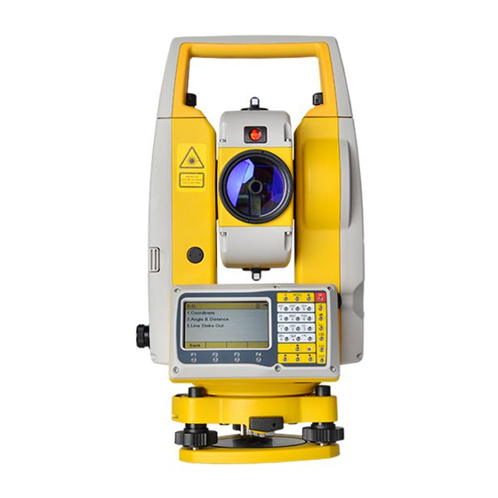
1. INTRODUCTION 1.1 Appearance Description Description Collimator Handle Eyepiece Objective Lens Vertical Tangent Screw Center Mark Vial Bubble Battery Unit Plummet Horizontal tangent Screw Display Unit with Keypad EDM Trigger Key Circular Bubble Tribrach... -
Page 9: Keyboard
1.2 Keyboard a) Quick Key b) Power Key c) Alphanumeric Keypad d) Measurement Key e) Backspace/ESC/ENT f) Navigation Key g) Function Keys Description Quick-access to transfer the input mode between α alphabets and numbers MENU Quick-access to main menu Quick-access to star key for basic settings On/Off key. -
Page 10: Screen
1.3 Screen The screen can be divide into four parts: A) Title Status Icon C) Active Field D) Function Key 1.4 Status Icon Icon Description Input status. Click to set the input mode. Bluetooth status. Click to switch on or off. Target status. -
Page 11: Function Key
1.6 Function Key Menu Function Key Description Angle 0 Set Set horizontal angle to 0 Hold Hold the horizontal angle HA Set Input the horizontal angle Vertical angle in percent (%) mode Switch between horizontal right or left Switch between V0 or H0 Distance Meas. - Page 12 1.7.1 Target Check the settings of target. Click or use the navigation key [ ][ to switch the target. ▶ Target The default value of prism constant is -30. It can be defined by manual. 1.7.2 E-Bubble Check the settings of E-bubble. [F2]XY ON: Turn on (Under dual axis) [F3]X ON: Turn on (Under single axis) [F4]OFF: Turn off the E-bubble...
- Page 13 1.7.4 Meas. Mode Check the settings of measure mode. Click or use the navigation key to select the measurement among Fine (Single/ 2times/ 3times/ 4times/ 5times), Repeat or Tracking mode. ▶ Measure Mode 1.7.5 Laser Pointer Click to turn on or off the laser pointer for easier target aiming. 1.7.6 Settings Quick access to setting page.
-
Page 14: Operation
2. OPERATION 2.1 Preparation Unpacking Lay down the case lightly with the cover upward. Unlock the case, and take out the instrument. Storage of Instrument Cover the cap, put the instrument into the case with the vertical clamp screw tightened and circular vial upwards (lens towards tribrach). 2.2 Instrument Setup 1) Setting up the tripod A. - Page 15 Slide the instrument by loosening the tripod screw; place the point on the center mark of the optical plummet. Sliding the instrument carefully as to not rotate the axis will allow you to get the least dislocation of the bubble. 3) Roughly leveling by the circular vial A.
-
Page 16: Battery
centered in all directions. If the laser or optical plummet doesn’t stay at the center position after levelling, please slightly loosen the screw under the tripod head and move the instrument (don’t rotate the instrument) until the equipment is on the station point. Tighten the screw and level the instrument again. Repeat these steps until the instrument is precisely centered and leveled. -
Page 17: Tribrach
When the indicator on the charger is red, the charging process has begun. When indicator turns green, the charging has finished. For safety, please pull out the battery and charger in time. In order to get the maximum service life, please charge the battery at least once in a month. -
Page 18: Eyepiece Focusing
stub. Turn the locking knob about 180° clockwise to mounting the instrument. 2.5 Eyepiece Focusing Sight the Telescope to bright place and rotate the eyepiece tube to make the reticle clear. Roughly collimate the target by the top of the triangle mark on EDM cover. -
Page 19: Angle Measurement
3. ANGLE MEASUREMENT Press under basic measurement page to activate the function of angle measurement. 3.1 [F1] 0 Set Set the horizontal angle of the first target as 0°00’00”. Then aim at the other target to measure the HA between two points. [F1] 0 Set: Set the current HA as 0. -
Page 20: F3] Ha Set
3.3 [F3] HA Set Input the horizontal angle by manual. The value will apply to the target. [F3] HA Set: Input the requested value 3.4 [F1] V% [F1] V%: Switch the display method of vertical angle between degree and percent. [F4]1/2, [F4]2/2: Switch the page of function keys Note:... -
Page 21: F2] R/L
3.5 [F2] R/L Measure the target in both two side (Face 1/2) will effectively cancels out the operation error to obtain maximum accuracy for measurement. [F2] R/L: Switch the horizontal angle between HR (horizontal right) and HL (horizontal left). 3.6 [F3] VA The vertical angle can be defined by horizontal zero or vertical zero. -
Page 22: Distance Measurement
4. DISTANCE MEASUREMENT Press under basic measurement page to activate the function of distance measurement. 4.1 [F1] Meas. Measure the target to get the data of SD, HD and VD. The unit is “m” (meter) in default. [F1] Meas.: The result of measurement will be updated after the beeping. -
Page 23: F3] S.o
4.3 [F3] S.O This function calculates the distance elements (SD/HD/VD) to stakeout points. [F3] S.O: Click to enter the page of distance stake out [F1] SD : Slope distance [F2] HD : Horizontal distance [F3] VD : Vertical distance [F4] OK: Confirm the stake-out value [F1] Meas. -
Page 24: Coordinate Measurement
5. COORDINATE MEASUREMENT Press under basic measurement page to activate the function of coordinate measurement. The coordinates of the unknown point are calculated as shown below: Station: (N0,E0,Z0) Prism center: (n,e,z) Unknown point: (N1,E1,Z1) N1=N0+n E1=E0+e Z1=Z0+INS.HT+Z R.HT - 5.1 [F1] Meas. [F1] Meas.: Measure the point to get the N, E and Z coordinate based on the occupied point. -
Page 25: F2] Mode
When lacking the data of occupied point, N3 will use the value you inputted last time as the current station point. 5.2 [F2] Mode Change the mode of measurement among fine (N times), repeat or tracking mode. [F2] Mode. : Switch the mode of measurement. -
Page 26: F1] R.ht
5.4 [F1] R.HT Under prism mode, it’s necessary to set the reflector height. [F1] R.HT: Input the height of reflector by manual 5.5 [F2] I.HT [F2] I.HT: Set the height of instrument by manual. If your N3 total station features LPDM module for Auto Height: [F3] Meas.HT: Activate the function of auto height, from 0.5m to 3m. -
Page 27: Menu
6. MENU Press [MENU] under basic measurement screen to enter the menu of N3. Click or use navigation key to select the item. 1) Collect Station 2) Stake Out Data 3) COGO Settings 4) Program Adjustment [F3] Time: Check the current time and date [F4] Info: Check the information of total station, including model name, serial... -
Page 28: Collect
7. COLLECT 7.1 Data Collect Collect and record the point by angle, distance or coordinate measurement. [F1] Meas.: Click or press EDM trigger key for measurement [F2] Switch: Switch the measurement among angle, distance and coordinate [F3] R.HT: Reflector height [F4] Save: Save the current data as a new point 7.2 Distance Offset... -
Page 29: Plane Offset
[F1] Meas.: Measure the target [F2] Coord.: Check the coordinate of offset point 7.3 Plane Offset This function calculates the point which cannot be measured directly from the other three points in same plane. Those three points (P1/P2/P3) can be measured, inputted or selected from the data list to define a plane. -
Page 30: Column Offset
7.4 Column Offset This function calculates the coordinate of a hidden point (P0) that is not directly visible inside from the center (P1) and edge (P2/P3) of column. [F1] Meas./ReMeas.: Measure the center or edge of column [F4] Next: Aim at the left and right edge based on the guidance [F4] Calc.: Calculate the coordinate of hidden center... -
Page 31: Mlm
7.5 MLM MLM, is mainly used to compute the HD/ VD/ SD/ azimuth difference between two target points, and this function can be selected under two methods: 1) MLM Radial(A-B, A-C) , lock the start point 2) MLM Cont. (A-B, B-C) , unlock the start point. -
Page 32: Rem
7.6 REM When you need the information of a target which is hard to reach or hang in the air, REM can help you measure the point. Set a reflector perpendicular to target to finish the job. [F1] Meas.: Input the reflector height before measure the prism. -
Page 33: Stake Out
8. STAKE OUT This program calculates the required elements stakeout points from reference line, coordinates or angles, horizontal distances and heights. 8.1 Coordinate coordinate inputted, created or selected from data list. [F1] Input: Input coordinate directly [F2] New: Create and save a new point with coordinate to stake out [F3] Call: Call/Select point from data list Adjust the horizontal angle to find the... -
Page 34: Angle & Distance
8.2 Angle & Distance Stake out the angle (azimuth) and distance (HD, VD) by inputting the relative position between stakeout point and station point. Adjust the horizontal angle to find the direction until value becomes 0. [F1] Meas.: Measure to find the stake out point on site based on the guidance [F2] Back: Back to previous page [F3] 1/3: Switch the display of guidance... -
Page 35: Reference Line
8.3 Reference Line This function calculates the coordinate of unknown point through two known Offset Offset points (P1, P2) and the offset distance Unknown Target from reference line (P1-P2). P1 and P2 can be measured, inputted or selected from data list. [F1] Meas.: Measure the point as P1, P2 [F2] Call: Select the point from memory [F3] Input: Input the coordinate as P1, P2... -
Page 36: 9, Cogo
9. COGO COGO in N3 total station included the functions of coordinate calculation, inverse calculation, area & girth, point to line and point projection. 9.1 Calc. XYZ (Coordinate) Calculate the unknown coordinate of target based on the known relationship (azimuth, HD, VD) from two points. The start point can be measured [F1], inputted [F3] or selected [F2] from data list. -
Page 37: Area & Girth
Those two points can be measured, inputted or selected from data list. 9.3 Area & Girth Calculate the area and girth by at least 3 points. points added measurement, data select or manual input. [F1] Add: Add a new point in the list [F2] Delete: Delete the selected point [F4] Calc.: Calculate the area and girth Note:... -
Page 38: Point To Line Inverse
9.4 Point to Line Inverse Define a straight line by start point P1 and P2, then P3 as offset point. This function calculates the coordinate P2’ horizontal distance P3’ ’ perpendicular point P4 between offset ’ point P3 and Line P1-P2. P1’... -
Page 39: Point Projection
9.5 Point Projection Define a straight line by start point P1 and P2, then P3 as offset point. This function calculates the coordinate and distance of perpendicular point P4 between offset point P3 and line P1-P2. The known point P1, P2 and P3 can be measured, inputted or selected from data list. -
Page 40: Road
10. ROAD This program enables users to easily define a line, curve or transition curve as a reference to measure or stake out. It supports chainages, well incremental stake-outs and offsets. Before starting road program to design and stake-out, please set job, station and backsight at first. - Page 41 2) Straight Line The parameter of straight line only included the length. Note: The value should be positive 3) Curve The parameter of curve included the radius and length. Note: The value of radius depending on the direction. When the curve turns right, the value should be positive;...
- Page 42 4) Transition Curve parameter transition curve included parameter of transition, start and ending radius. Note: When the value of radius is positive, the transition parameter A will be a symbolic number. The value of parameter A is depending on the forward direction of curve.
-
Page 43: Vertical Alignment
10.1.3 Import Horizontal Alignment [F2] Call: Select the file from USB 10.1.4 Clear Horizontal Alignment Clear all the horizontal alignment 10.2 Vertical Alignment A vertical alignment consists of a series of intersections, including a chainage, elevation and curve length. The length of start point and end point must be zero. -
Page 44: Road S.o
10.3 Road S.O In the Roads stake-out, user should stake-out points on the center line at first, Differ.(L) Differ.(R) then the chainage for both sides. Interval: Interval between the current stake to next stake. Interval Differ.: The left and right difference (offset) from the central line VD: Vertical difference between left and right chainage and the center line... -
Page 45: Calculation
10.4 Calculation 10.4.1 Calculate the coordinate of single point Enter the mileage and point name to calculate the coordinate of point 10.4.2 Calculate the coordinate of multi-points Enter the mileage of start point and end point, with interval and point number. N3 will calculate the coordinate of all the points which matches the requirements in once. -
Page 46: Station
11. STATION 11.1 Known Point Input, create or select a point from the memory with instrument height as the station point. If your N3 features the LPDM module, you can activate the auto height function by [F3]. [F4] Next: Click to select the orientation method (by coordinate or angle). - Page 47 If necessary, measure the backsight with angle, distance and coordinate for double check. 11.1.2 By Angle Input the point name, code, azimuth angle and reflector height as backsight. [F4] Orient: Sight the HA of current HA as azimuth. If necessary, measure the backsight with angle, distance and coordinate for double check.
-
Page 48: Resection
11.2 Resection A resection sets up the station by using the angle and distance measurements from 7 points in maximum. Calculation will start automatically when enough measurements are taken. --- The intersection angle among known points should less than 180 degrees. Input, select or measure the points for calculation. -
Page 49: Point To Line
11.3 Point to Line This function calculates the coordinate of unknown occupied point from two known points. Measure known points A & B to define a coordinate system. Point A as (0,0,0), and Line A-B as N axis. [F1] Meas.: Measure two points to define the axis N. -
Page 50: Height Transfer
11.4 Height Transfer This function is used for adjusting the height of station, transferred by the coordinate of known point. The known point can be inputted, created or selected from the data list. [F1] Meas.: Measure value horizontal and vertical distance. [F4] OK: Save the changes and set the station with the calculated instrument height. -
Page 51: Data
12. DATA 12.1 Job Click or use the navigation key to select the job. [F1] Delete: Delete the selected job [F2] New: Create a new job [F3] Search: Search the job in memory [F4] Edit: Edit the selected job 12.2 Meas. Data Click or use the navigation key to select the measured data. -
Page 52: Coord. Data
12.3 Coord. Data Click or use the navigation key to select the coordinate data. [F1] View: View the details. [F2] Search: Search the point in memory [F3] Add: Add new point with coordinate [F4] 1/2, 2/2: Switch to the next/last page [F1] First: Switch to the first page [F2] Last: Switch to the last page [F3] Delete: Delete the selected point... -
Page 53: Data Export
12.5 Data Export This function is used to transfer the coordinate data or raw data, via USB or Bluetooth. Use 1.USB Stick as an example. Input the file name, which will be saved under the root directory of USB Stick. Select the data type between raw data and coordinate data. -
Page 54: Data Import
12.6 Data Import Import the data from USB [F1] Back: Return to last page [F2] Call: Select the file [F4] OK: Confirm the type and order Select the job to import the data from USB stick to the internal memory. 12.7 Memory Check the status of internal memory, with the information of used, unused and... -
Page 55: Settings
13. SETTINGS 13.1 Measurement Change the setting of angle, distance and coordinate measurement. Angle Z0/H0 Horizontal 0 Zenith 0 Tilt X-ON XY-ON Distance Temperature Sensor Pressure Auto: On/Off Other Scale Elevation (Z) Grid TP Sensor Constant K Measure Mode Mode Times Target Prism/ Sheet/... -
Page 56: Unit
13.2 Unit Change the setting of display unit, including angle, distance, temperature and pressure unit. Unit Angle Degree Dist. Temp. ℃ ℉ Pressure mmHg inHg 13.3 Bluetooth Change the setting of Bluetooth. Bluetooth On/Off Name Input Name Password [F3] Default: Reset settings Bluetooth as default. -
Page 57: Backlight
13.4 Backlight Change setting backlight, including battery manage, display unit and the reticle illumination Battery Sleep 0-9 mins Manage Power Off 0-60 mins Display Auto Unit Dual Side Keypad Class Reticle On/Off Illumination Class 13.5 Time & Date Change the setting of time and date. Time &... -
Page 58: Data Collect
13.6 Data Collect Change the settings of data collect. Data Collect By Measure Collect Auto Save By Manual Auto 13.7 Choose Job Change the setting of job chosen. Turn on or off the job chosen page. 13.7 Touch Screen Turn on or off the sensor of touch screen. -
Page 59: Auto Height
This revolutionary function is now available in South N3 Series total station. ▶ Star Key, chapter 1.6.7 The function can by activated under the... -
Page 60: Inspection & Adjustment
15. INSPECTION & ADJUSTMENT The instrument has passed the procedure of inspection and adjustment before shipping to your side. However, after long periods of transportation or the changeable environment, some influences may occur to the internal structure. Before the instrument is used for the first time, please check and adjust the f unctions we introduced in this session to ensure the precision of the job. -
Page 61: Circular Vial
15.2 Circular Vial Inspection It is not necessary to adjust the circular vial, except the bubble is not in the center after the adjustment of plate vial. Adjustment If the bubble of the circular vial is not in the center, adjust the bubble to the center by using the adjusting pin or hexagon wrench. -
Page 62: Inclination Of Reticle
Adjustment 1. Enter the page of tilt adjustment under Menu.8 Adjustment. 2. Aim at a target in Face 1 (HL) 3. Aim at the same target in Face 2 (HR) 4. If the value of X and Y are within the adjustment range, then press F4 [OK] to update the correction value;... - Page 63 2. Move object A to the edge of the field of view, point A’ by rotating the vertical tangent screw. 3. Adjustment is not necessary if object A moves along the vertical line of the reticle and point A’ still in the vertical line. Otherwise, as picture shown, A’...
-
Page 64: Perpendicularity Between Sight Of View & Horizontal Axis (2C)
15.5 Perpendicularity between Sight of View & Horizontal Axis (2C) Inspection 1. Set object A at a far distance at the same height as the instrument, leveling the instrument and turn on the power (e.g. HL=10°13’10”). 2. Sight object A in horizontal left and read value of HA. (e.g. HR= 190°13’40”). -
Page 65: Vertical Index (I Angle) & V0 Adjustment
15.6 Vertical Index (I Angle) & V0 Adjustment Inspect this parameter after chapter 15.3 and 15.4 Inspection 1. After leveling the instrument, collimate at any target A in HL. Record the value as L. 2. Rotate the EDM and aim at the target A in HR. Record the value as R. 3. -
Page 66: Optical Plummet
4. Press [F4]OK to confirm the revised I-Angle 5. If the Index Difference does not meet your requirements, please redo the steps above. Please carefully repeat these steps to ensure the proper result. Or contact your local dealer for further help. 15.7 Optical Plummet Inspection 1. -
Page 67: Laser Plummet
plummet which falls on the paper in every 90°. Point A, B, C, and D. 3. Draw lines that attach AC and BD and mark the intersection point of the two lines as O. 4. Adjust the four adjusting screws of the optical plummet with an adjusting pin until the center mark coincides with Point O. -
Page 68: Instrument Constant (K)
15.9 Instrument Constant (K) The Instrument constant has been checked and adjusted in the factory, and K=0. Please do not modify the constant without permission. Inspection Mount and level the instrument on Point A on flat ground. Use the vertical hair to mark Point B and Point C with the distance of 50m on the same line, and collimate the reflector accurately. -
Page 69: Coincidence Between Sight Of View % Emitting Axis
15.10 Coincidence between Sight of View & Emitting Axis Inspection 1. Set a target 50m away from the instrument. 2. Aim and measure the center of target. 3. Rotate the tangent screw to launch electric collimation and make the light path of EDM unblocked. In the bright zone, find the center of emitting photoelectric axis. -
Page 70: Specifications
16. SPECIFICATIONS TELESCOPE Image Erect Tube length 152mm Effective aperture 45mm (DTM: 50mm) Magnification Field of view 1°30’ Resolving power 3” Minimum focus 1.5m Reticle illumination 10 brightness level ANGLE MEASUREMENT Accuracy 2” Measuring method Absolute encoding Diameter of disk 79mm Minimum reading 1”... - Page 71 Atmospheric correction Manual input, auto correction Prism constant Manual input, auto correction Temperature correction Sensor reading Distance reading Max: 99999999.999m; Min: 1mm COMPENSATOR System Liquid, dual axis Working range ±6’ Accuracy 1” PLUMMET ±1.5mm @1.5m Accuracy Brightness 5 brightness level Laser Wavelength 635nm...
- Page 72 INTERFACE Data interface USB flash disk, Bluetooth BATTERY Type Lithium, 7.4V Operating time 8 hours VIAL Plate vial 30”/2mm Circular vial 8'/2mm GENERAL Storage 16000 points IP54 Size 206*200*353mm Weight Approx. 6.0kg * Under good conditions, Kodak Gray card, 80% reflectance...
-
Page 73: Safety Guide
17. SAFETY GUIDE 17.1 INTERNAL DISTANCE METER (VISIBLE LASER) Warning The total Station is equipped with an EDM of Laser Class 3A/III a and it is verified by these labels as follows: There’s an indication label “CLASS III LASER PRODUCT” above the vertical clamp screw on Face Left as well as on the Face Right. - Page 74 Warning When the laser beam emits on prism, mirror, metal surface, window, it might be dangerous to look directly by the reflecting light. Prevention Do not stare at the direction which the laser beam might reflects. When the laser is opened, do not look at it near to the optical path or the prism.
- Page 75 through the restricted area (harmful distance*), and there are persons taking activities, users must stop the laser beam in time. d. The optical path of the laser beam should be set higher or lower than the line of sight. e. When the laser instrument is not in use, users should keep it well. It is not allowed for operation unless the user is authenticated.
- Page 76 17.2 LASER PLUMMET The internal laser plummet sends out a ray of red visible laser beam from the bottom of the instrument. This product is classified as Class 2/II laser product. Class 2 laser product is in accordance with the following standard: IEC 60825-1:1993 “SAFETY of LASER PRODUCTS”...
Need help?
Do you have a question about the N3 Series and is the answer not in the manual?
Questions and answers
my south N3 Shows angle error 2 pop up message how can that be corrected or adjusted in the lab
To correct or adjust the angle error 2 (2C) on a South N3 Series Total Station, follow these steps:
1. Inspection
- Set object A at a far distance at the same height as the instrument.
- Level the instrument and turn on the power.
- Sight object A in the horizontal left position and read the horizontal angle (HA).
- Rotate the telescope to the horizontal right position and read the HA again.
- Calculate 2C using the formula: 2C = HL - HR ± 180°.
- If the value exceeds the acceptable range (e.g., ±20”), adjustment is required.
2. Adjustment
- Use the tangent screw to adjust the horizontal angle to the correct reading.
- Eliminate the observed error by fine-tuning the settings.
- Repeat the inspection steps to verify the adjustment.
This process ensures that the perpendicularity between the sight of view and the horizontal axis is correctly aligned.
This answer is automatically generated
@Mr. Anderson thank you, i have been able resolve the issue i have another issue also There is pop up that keeps showing and once it does i cannot be able to do any operation see attached photo how can also fix this issue