
Related Manuals for IDTECH ViVOpay


Summary of Contents for IDTECH ViVOpay
- Page 1 ViVOpay ™ VP5300 User Manual 80152500-001 Rev. O 7 April, 2021 ID TECH 10721 Walker Street, Cypress, CA 90630 Voice: (714) 761-6368 Fax: (714) 761-8880...
- Page 2 ID TECH. ID TECH is a registered trademark of International Technologies and Systems Corporation. ViVOpay and Value through Innovation are trademarks of International Technologies and Systems Corporation. Other trademarks are the property of the respective owner.
- Page 3 VP5300 User Manual Revision History Date Revision Changes Author 04/07/2021 Reimplemented Revision History log Updated Current Draw table with L80 specs Page | 3...
-
Page 4: Table Of Contents
VP5300 User Manual Table of Contents 1. OVERVIEW ..................................6 1.1. Features ....................................6 1.2. VP5300: Approvals ................................8 2. VP5300 SPECIFICATIONS .............................. 9 3. VP5300 ELECTRICAL REQUIREMENTS ........................11 3.1. Power Consumption ................................11 3.2. Current Draw ..................................11 3.3. - Page 5 VP5300 User Manual 17. IC COMPLIANCE WARNING ............................44 18. CAUTIONS AND WARNINGS ............................45 Page | 5...
-
Page 6: Overview
VP5300 User Manual 1. Overview ID TECH's VP5300 is a compact, ruggedized insert-style credit card reader designed to support MSR (magstripe) and contact EMV, plus contactless EMV (when the device is mated with the VP5300’s NFC antenna). The VP5300 is designed to deliver MSR, EMV, and NFC (contactless) payment acceptance with SRED security and reliability in unattended payment scenarios, such as Parking, Fueling, ATM, Ticketing, and Payment Kiosks (among others). - Page 7 VP5300 User Manual Support for DUKPT key management of data and/or MAC keys • TR34 Remote Key Injection Protocol • Mechanical front switch • 2 User-accessible SAMs (Note: the VP5300 SAMs only support a 3V power supply) • Metallic bezel meets IK 10 impact rating •...
-
Page 8: Vp5300: Approvals
VP5300 User Manual 1.2. VP5300: Approvals Item Regulation & Class CE EN55032/EN55035, Class- B FCC Part 15, Class-B RoHS Compliant UL Compliance with UL regulation REACH Compliance with REACH regulation USB IF Compliance with USB IF regulation IC Compliance with IC regulation EMV Contact L1 &... -
Page 9: Vp5300 Specifications
VP5300 User Manual 2. VP5300 Specifications Physical VP5300 Dimensions 136.2 mm from back of mounting surface x 102.8 mm flange width x 72.6 mm flange height (LxWxH) NFC Antenna Bezel Dimensions 65mm x 54mm x 14.5mm (LxWxH), plus 15.5mm-deep M4 studs protruding from the back of the unit Structure Material Plastic, PC UL 94V-0 Housing Color Black... - Page 10 VP5300 User Manual B: NRZ-L, BPSK ISO 18092 ISO 21481 (PCD & NFC) Typical Read Range 4-6 cm (1.5 to 2.3 inches) NFC Antenna Electrical Specifications Reader Input Voltage Supplied by the VP5300 <500mA (@9VDCIN) Working Current Rated power <3.8W Maximum field strength 2.6 dBuA/m at 3 m Page | 10...
-
Page 11: Vp5300 Electrical Requirements
VP5300 User Manual 3. VP5300 Electrical Requirements Voltage requirement: 9VDC (minimum) is recommended, to 12V maximum. 3.1. Power Consumption Stop Mode (with NFC) ≦ 85uA Stop Mode (without NFC) ≦85uA • • 3.2. Current Draw VP5300 OPERATING MODE: 12VDC 9VDC Normal 83mA 115mA Normal+MSR 86mA... -
Page 12: Low-Power Modes
VP5300 User Manual 3.3. Low-Power Modes The VP5300 has two low-power modes: Sleep Mode and Stop Mode. Power management is at the discretion of the application developer and set with firmware command F0-03 (which is described in the NEO Interface Developers Guide, available on request). Note that using the F0-03 command to control the unit's power state is limited to RS-232 operation and is not available in USB mode. -
Page 13: Vp5300 3-View Drawing
VP5300 User Manual 4. VP5300 3-View Drawing Page | 13... -
Page 14: Nfc Antenna 3-View
VP5300 User Manual 5. NFC Antenna 3-View Antenna mounting details: Page | 14... -
Page 15: Vp5300 Installation
(when viewed head- on; the side nearest the molded-in ViVOpay logo), must be depressed when the unit is mounted. Ensure that the gasket is compressed to a degree necessary to ensure anti-tamper nub depression (and to protect against unnecessary moisture ingress). -
Page 16: Reader Drainage Holes
VP5300 User Manual 6.2.1. Reader Drainage Holes VP5300 readers have three drainage holes, shown below. When mounting, make sure to keep the drainage holes exposed to allow liquid to drain from the reader. Page | 16... -
Page 17: Mounting The Vp5300 External Nfc Antenna
VP5300 User Manual 6.3. Mounting the VP5300 External NFC Antenna Refer to the VP5300 Antenna 3-view drawing. If you are using the VP5300’s contactless capability, you will need to install the optional NFC antenna and its cabling. Use the following instructions to mount the antenna on the exterior of a kiosk. Note: Product installers should experiment with and verify the orientation of the NFC Antenna before marking and drilling mounting holes, ensuring that the antenna is far enough away from the main body of the VP5300 so that insertion of a "tap card"... - Page 18 VP5300 User Manual Drill the two access holes (14.0 mm, 0.551 inch) holes using a 35/64 drill bit. Use the nuts that are supplied with the unit (in plastic bag). Route the end of the cable (80152235-001) with the RJ-45 connector through the matching 14.0 mm (0.551 inch) hole into the kiosk.
- Page 19 VP5300 User Manual Use the four nuts to secure the NFC Antenna to the surface of the kiosk. Make sure to tighten the nuts securely so that the antenna does not move freely on the outside surface of the kiosk. Note: Tighten the nuts to 5-7 in/lbs.
-
Page 20: Recommended Mounting Locations
VP5300 User Manual 6.3.1. Recommended Mounting Locations Note: The 10mm gap described in the above diagram can be either an air gap or flush plastic material; the restriction is that metal needs to be more than 10mm away from the antenna. 6.3.2. -
Page 21: Attaching The Cables From The Antenna To The Vp5300
VP5300 User Manual 6.4. Attaching the Cables from the Antenna to the VP5300 1. Attach the SMB barrel end of the cable (80152236-001) from the antenna to the SMB post of the VP5300. The connector slides on. 2. Attach the 8-pin end of the cable (80152236-001) from the antenna to the VP5300, where the receptacle sits next to the RJ-45 (Ethernet) receptacle. -
Page 22: Connecting To The Host Port
VP5300 User Manual 6.6. Connecting to the Host Port Use 9-pin Joint Tech P/N A2002H-09P (or equivalent) for the mating connector. See diagrams below for RS-232 or USB, as appropriate. 6.7. VP5300 External Cable Pin Assignments: RS-232 6.8. VP5300 External Cable Pin Assignments: USB Page | 22... -
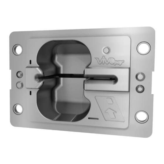
Page 23: Engaging The Removal Detection Switch For Testing
VP5300 User Manual 6.9. Engaging the Removal Detection Switch for Testing The front panel of the VP5300 incorporates a removal-detection switch behind the bezel's rubber gasket, on the unit's right-edge flange (when viewed head-on, as in the illustration below). Engaging the removal-detection feature is only necessary when attempting to pair a VP5300 with a compatible ID TECH PIN pad, such as the SmartPIN L100 or L80 keypad for PIN functionality. -
Page 24: Installation Notes
• Tie all cables neatly with nylon cable-ties and route them so that they are inaccessible and invisible to customers. Label the cable ends as "host," "ViVOpay," and "power" to simplify connection testing or component replacement, particularly when untrained individuals might be involved. -
Page 25: Led Management
VP5300 User Manual 7. LED Management There are two LEDs. One is the user-interface LED on the front bezel of the reader; the other (diagnostic) LED is on the back. Front LED Status The LED turns green in idle waiting. •... -
Page 26: Diagnostic Led Status
VP5300 User Manual 7.1. Diagnostic LED Status The LED on the back of the VP5300 is intended to be used for diagnostic purposes. LED status: 1. Off 2. Solid – No communication with its host. 3. Flashing (1 sec on, 1 sec off) – Communicating with its host. LED Colors: Amber –... - Page 27 VP5300 User Manual State Green LED Amber LED Red LED Indicating Service action Flashing Firmware downloading and Flashing Green Wait for download to finish. Amber programming in progress. In ready state but no Solid Green Check connections. communication with its host. Command sent to reader;...
-
Page 28: L100 And L80 Diagnostic Messages
VP5300 User Manual 7.2. L100 and L80 Diagnostic Messages VP5300 units connected to L100 and L80 PIN Pads may display the following diagnostic messages. Message ID Display Message Description Message ID Display Message Description Tampered Device is tampered. Deactivated Device is not activated. Activated Device is activated. -
Page 29: Tamper And Failed Self-Check Indicators
VP5300 User Manual 7.3. Tamper and Failed Self-Check Indicators The VP5300 displays the following indicators when it has been tampered or has any of the other following internal issues, such as an expired certificate, missing key, or similar fault discovered during a self-check. The VP5300’s diagnostic LED is located on the back of the reader, near the antenna cable connectors. -
Page 30: Using The Vp5300 To Make A Contactless Purchase
VP5300 User Manual 8. Using the VP5300 to Make a Contactless Purchase 8.1. Presenting Proximity Cards or NFC Phones The VP5300 allows for credit/debit card purchases using Contactless technology when the optional NFC antenna is installed. Present the card or phone in close proximity to the front portion of the antenna module. Present the card or phone so that maximum surface area is parallel to the antenna module as shown below. -
Page 31: Pairing With Pin Pad
VP5300 User Manual 9. Pairing with PIN Pad The VP5300 is designed to be paired with ID TECH's SmartPIN L100 or L80 keypads to create a full chip- and-PIN solution. Follow the pairing procedures below to use the L100 or L80 with the VP5300. -
Page 32: Setting Up The Vp5300
VP5300 User Manual of the new Password 2 in your records. 9. The device prompts to reenter the password. Enter the new Password 2 again to confirm it. After entering the new Password 2 for a second time, the device beeps twice to confirm the input. - Page 33 VP5300 User Manual 3. Open Commands > EMV > Terminal Config to expose command names. Select the Set Config #3 command and click the Execute Command button. This configures the VP5300 reader to accept 3C configuration settings. 4. Find the Save Terminal Data command (see below). When you select it, the upper portion of the center panel will change appearance and show a CONFIG dropdown menu along with a TLV text area.
-
Page 34: Pair The Devices
VP5300 User Manual 9.3. Pair the Devices 1. Open Device > Send NEO Command. Enter 63 for Cmd and 01 for Sub in the text boxes at the top of the center panel (as shown below). This command pairs the readers. Page | 34... - Page 35 VP5300 User Manual 2. The VP5300 is now fully configured to do PIN-based transactions (if the presented credit card supports them). Verify that the VP5300’s front removal detection switch is firmly pressed down. The pressure switch is located on the front bezel, right side, behind the rubber gasket. If the unit is not mounted in a kiosk or other fixture, you can temporarily engage the pressure switch by attaching a strip of metal to the right side of the flange as shown below (note the wing nuts): 3.
-
Page 36: Enabling Smartpin L100 Devices
VP5300 User Manual 9.3.1. Enabling SmartPIN L100 Devices 1. The L100 or L80 front display now shows two options: Enable PinPad, and Enable CR (in this case, CR means "card reader"). Use the # and * keys to scroll up or down. Select Enable CR and press Enter. -
Page 37: Enabling Smartpin L80 Devices
VP5300 User Manual 9.3.2. Enabling SmartPIN L80 Devices 1. The L80 front display now shows the Enable CR option (in this case, CR means "card reader"). Press Enter. Setup is now complete. Execute the Start EMV Transaction command in the USDK Demo, or start a transaction from your own software, and then insert a PIN debit card. -
Page 38: Implementing Whitelists
VP5300 User Manual 10. Implementing Whitelists For instructions on implementing Whitelists for the VP5300, contact your ID TECH representative to receive the user guide ID TECH Implementing Whitelists, available under NDA. 11. RF Interference Q. Why do I need to know about RF interference? A. - Page 39 VP5300 User Manual immune to high signal levels of another frequency; frequency is an important factor. Some electronic system components are internally shielded and have a very high immunity to interference; but generally, most equipment has not been so engineered. Page | 39...
-
Page 40: Updating Vp5300 Firmware
VP5300 User Manual 12. Updating VP5300 Firmware Users can update VP5300 firmware with a Windows computer via either serial or USB interfaces. Note: Before you begin, go to the VP5300 product page on the ID TECH Knowledge Base, download the Firmware update package; VP5300; production ZIP file, and extract it to your computer. You will also need to install ID TECH’s Universal SDK Demo app, available free on the ID TECH... - Page 41 VP5300 User Manual 4. In the Firmware Type dialog, enter 255 for K81 FW and click OK. 5. In the File Explorer window, navigate to the directory where you saved the VP5300 firmware update, open the FirmwareApp directory, and select the FW file that starts with VP5300 v1.00...
-
Page 42: Decommissioning Pci-Certified Devices
VP5300 User Manual 13. Decommissioning PCI-Certified Devices All PCI devices require proper decommissioning prior to device disposal in order to ensure the protection of all sensitive financial card data. For instructions on decommissioning your device, see Decommissioning of PCI-Certified Devices on the ID TECH Knowledge Base. - Page 43 VP5300 User Manual Symptom Possible Cause Remedy • Try a different card/fob. • Check to see if card/fob is damaged. • Verify that correct firmware is loaded on reader (local support representative only). • Power cable plug is fully inserted. •...
-
Page 44: Fcc Regulatory Compliance Notices Class B Equipment
VP5300 User Manual 16. FCC Regulatory Compliance Notices Class B Equipment This device complies with Part 15 of the FCC Rules. Operation is subject to the following two conditions: (1) this device may not cause harmful interference, and (2) this device must accept any interference received, including interference that may cause undesired operation. - Page 45 VP5300 User Manual 18. Cautions and Warnings Warning: Avoid close proximity to radio transmitters which may reduce the capability of the reader. Avertissement : Évitez la proximité d'émetteurs radio, ce qui peut réduire la performance du lecteur. Caution: Do not drop the device. Attention : Ne pas laisser tomber le lecteur Caution: Electrostatic sensitive device.
Need help?
Do you have a question about the ViVOpay and is the answer not in the manual?
Questions and answers