Table of Contents
Advertisement
SERVICE MANUAL
Ver. 1.0 2016.03
Motor and Platter
Drive system
Belt-drive
Motor
DC motor
Platter
296 mm dia. (aluminum die-cast)
Speeds
33 1/3 and 45 rpm, 2 speed
Wow and flutter
Less than 0.25% (WRMS)
S/N ratio
More than 50 dB (DIN-B) with the supplied cartridge
Tone Arm
Type
Dynamic balanced straight-shaped with soft damping control
Effective arm length
221 mm
USB Connectivity
USB Type B
Output port
USB 2.0
Cartridge
Type
MM
Stylus pressure
3 g
Output level
2.5 mV
General
Power supply
DC 5 V 2.0 A (AC adaptor)
Power consumption
3 W
Dimensions
430 x 104 x 366 mm (16 7/8 x 4 1/8 x 14 3/8 in)
(width/height/depth)
Weight
Approx. 5.4 kg (11.9 lb 19.5 oz)
9-896-278-01
Sony Video & Sound Products Inc.
2016C33-1
©
2016.03
Published by Sony Techno Create Corporation
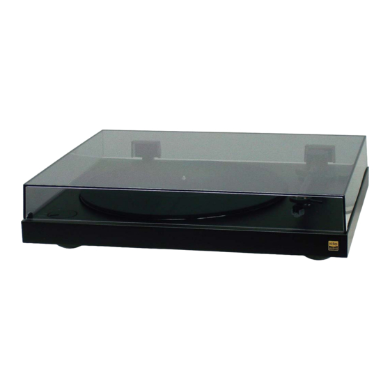
PS-HX500
SPECIFICATIONS
AC adaptor
HK-AR-050A200-US for the U.S.A. and Canada
Input
Output
HK-AR-050A200-EU for European countries
Input
Output
HK-AR-050A200-GB for United Kingdom
Input
Output
Supplied accessories
• Platter (with drive belt) (1)
• Rubber mat (1)
• Counterweight (1)
• Dust cover (1)
• 45 rpm adaptor (1)
Place the adaptor on the spindle for
playing a 17 cm (7 inch) vinyl record.
• Dust cover hinges (2)
• AC adaptor (1)
• PHONO cables with grounding wires (1)
• USB cable (1)
• Operating Instructions
• Warranty card
• Owner Registration Card (for customers in
the USA)
Design and specifications are subject to change without notice.
STEREO TURNTABLE SYSTEM
US Model
Canadian Model
AEP Model
UK Model
AC 100-240 V 0.35 A 50/60 Hz
DC 5 V 2.0 A
AC 100-240 V 0.35 A 50/60 Hz
DC 5 V 2.0 A
AC 100-240 V 0.35 A 50/60 Hz
DC 5 V 2.0 A
Advertisement
Table of Contents

Related Manuals for Sony PS-HX500


Summary of Contents for Sony PS-HX500
- Page 1 • Owner Registration Card (for customers in (width/height/depth) the USA) Weight Approx. 5.4 kg (11.9 lb 19.5 oz) Design and specifications are subject to change without notice. STEREO TURNTABLE SYSTEM 9-896-278-01 Sony Video & Sound Products Inc. 2016C33-1 © 2016.03 Published by Sony Techno Create Corporation...
-
Page 2: Table Of Contents
LES DIAGRAMMES SCHÉMATIQUES ET LA LISTE DES PIÈCES SONT CRITIQUES POUR LA SÉCURITÉ DE FONC- TIONNEMENT. NE REMPLACER CES COMPOSANTS QUE PAR DES PIÈCES SONY DONT LES NUMÉROS SONT DON- NÉS DANS CE MANUEL OU DANS LES SUPPLÉMENTS PUBLIÉS PAR SONY. -
Page 3: Servicing Notes
PS-HX500 SECTION 1 SERVICING NOTES The SERVICING NOTES contains important information for servicing. Be sure to read this section before repairing the unit. UNLEADED SOLDER NOTE OF REPAIRING THE BOARDS Boards requiring use of unleaded solder are printed with the lead- When the board installed by this unit is defective, replace the com- free mark (LF) indicating the solder contains no lead. - Page 4 PS-HX500 ASSEMBLING THE TURNTABLE REPLACING THE STYLUS Peel off the adhesive tape, pull and The stylus may become worn out, damaged, Note hold the red ribbon, and then hook or dirty beyond cleaning depending on Do not connect your turntable to a power outlet the drive belt around the motor your use case.
- Page 5 PS-HX500 ADJUSTING THE TONE ARM BAL- ADJUSTING THE STYLUS PRES- Unlock the tone arm lock and raise ANCE SURE AND THE ANTI-SKATING the tone arm from the tone arm FORCE Adjust the tone arm balance to keep the rest. tone arm horizontally balanced (zero...
- Page 6 PS-HX500 MEMO...
- Page 7 PS-HX500 SPEED ADJUSTMENT SHEET (STROBOSCOPE) Used in electrical adjustment (refer to page 15). Please enlarge to become diameter 292 mm. It will be 292 mm in the 200 % enlarge. Please adjust if necessary. 292 mm...
- Page 8 PS-HX500 MEMO...
-
Page 9: Disassembly
PS-HX500 SECTION 2 DISASSEMBLY • This set can be disassembled in the order shown below. 2-1. DISASSEMBLY FLOW STYLUS Note: Illustration of disassembly is omitted. (Refer to “REPLACING THE STYLUS” on page 4) 2-2. HINGE ASSY, DUST COVER ASSY (Page 9) 2-4. -
Page 10: Counter Weight
1 rubber mat Note 1: Make sure that the chamfered side of the rubber mat faces upward. The back side of the rubber is indicated by the SONY imprint. 2 Remove the belt from the pulley. pulley 5 belt belt... -
Page 11: Case
PS-HX500 2-5. CASE Note: When turning the main unit over, refer to “NOTE IN THE CASE OF THE REVERSING THE MAIN UNIT” on page 3. 2 seven screws 3 case bottom side 1 four screws (BTB3 front side 2-6. MAIN BOARD Note: When turning the main unit over, refer to “NOTE IN THE... -
Page 12: Foot Assy, Cover_Motor
PS-HX500 2-7. FOOT ASSY, COVER_MOTOR Note 1: When turning the main unit over, refer to “NOTE IN THE CASE OF THE REVERSING THE MAIN UNIT” on page 3. Note 2: All four foot assys (rubber + base) can be removed using the same procedure. -
Page 13: Motor Assy (M1)
PS-HX500 2-9. MOTOR ASSY (M1) Note 1: When turning the main unit over, refer to “NOTE IN THE Note 2: When replacing the motor assy, refer to “DC MOTOR SPEED CASE OF THE REVERSING THE MAIN UNIT” on page 3. -
Page 14: 2-10. Sw Board
PS-HX500 2-10. SW BOARD Note: When turning the main unit over, refer to “NOTE IN THE CASE OF THE REVERSING THE MAIN UNIT” on page 3. 2 connector 3 Draw the wire out of the groove. (CN901) 1 Remove the four solders. -
Page 15: 2-11. Tone Arm Assy
PS-HX500 SECTION 3 ELECTRICAL ADJUSTMENT 2-11. TONE ARM ASSY DC MOTOR SPEED ADJUSTMENT 3. The turntable is rotated at a rotation speed 33 rpm. When replace the motor, perform the DC motor speed adjustment. Note 1: When turning the main unit over, refer to “NOTE IN THE SPEED/POWER CASE OF THE REVERSING THE MAIN UNIT”... -
Page 16: Diagrams
PS-HX500 SECTION 4 DIAGRAMS 4-1. BLOCK DIAGRAM PS-HX500... -
Page 17: Printed Wiring Board - Sw Board
PS-HX500 THIS NOTE IS COMMON FOR PRINTED WIRING BOARDS AND SCHEMATIC DIAGRAMS. 4-2. PRINTED WIRING BOARD - SW Board - • Uses unleaded solder. (In addition to this, the necessary note is printed in each block.) For Printed Wiring Boards. -
Page 18: Printed Wiring Board - Main Board
PS-HX500 4-3. PRINTED WIRING BOARD - MAIN Board - • Uses unleaded solder. MAIN BOARD (COMPONENT SIDE) MAIN BOARD (CONDUCTOR SIDE) PS-HX500... -
Page 19: Schematic Diagram - Main Section (1/4)
PS-HX500 4-4. SCHEMATIC DIAGRAM - MAIN Section (1/4) - MAIN BOARD (1/4) R602 LINE MM PICK-UP C618 C601 IC601A C611 LINE 100u/16 C612 NJM4580 0.1u 4.7u/50 R610 220P R601 C619 C620 100u/16 0.1u C610 R611 A-8V PHONO 100P R613 R614... -
Page 20: Schematic Diagram - Main Section (2/4)
PS-HX500 4-5. SCHEMATIC DIAGRAM - MAIN Section (2/4) - MAIN BOARD (2/4) D3.3V IC301C TMS320C6748EZWT3 JK302 TRST TRST MMCSD0_DAT(4)/PRU1_R30(25)/GP4(1) RTCK MMCSD0_DAT(5)/PRU1_R30(24)/GP4(0) EMU1 EMU0 GP8(0) EMA_D(15)/GP3(7) EMA_D(14)/GP3(6) 2PIN7 EMU1 EMA_D(13)/GP3(5) EMU0 EMA_D(12)/GP3(4) R345 R346 D3.3V EMA_D(11)/GP3(3) EMA_D(10)/GP3(2) UART1_RxD/SATA_LED/GP1(1) EMA_D(9)/GP3(1) UART1_TxD/SATA_CP_POD/GP1(0) EMA_D(8)/GP3(0) -
Page 21: Schematic Diagram - Main Section (3/4)
PS-HX500 4-6. SCHEMATIC DIAGRAM - MAIN Section (3/4) - MAIN BOARD (3/4) IC301A TMS320C6748EZWT3 D1.2V D1.8V CVDD DVDD18 CVDD DVDD18 C346 C347 C348 C349 C350 C351 C352 C393 C394 C395 C396 C397 C398 CVDD DVDD18 0.1u 0.1u 0.1u 0.1u 0.1u 0.1u... -
Page 22: Schematic Diagram - Main Section (4/4)
PS-HX500 4-7. SCHEMATIC DIAGRAM - MAIN Section (4/4) - SW BOARD MAIN BOARD (4/4) Q914 C124EKA MOTOR R931 CHASSIS C937 SW901B SW901A IC904 0.1u BA08FP AP8V Q906 R937 C938 RRR030P03 10 1/6 W 100u/16 L905 FB(80) C914 W901 C913 C915... -
Page 23: Exploded Views
PS-HX500 SECTION 5 EXPLODED VIEWS Note: • -XX and -X mean standardized parts, so • The mechanical parts with no reference they may have some difference from the number in the exploded views are not sup- original one. plied. • Items marked “*” are not stocked since •... -
Page 24: Cabinet Section
PS-HX500 5-2. CABINET SECTION • Rear bottom view not supplied Supplied with not supplied Ref. No. 61. not supplied supplied not supplied not supplied Note: The stylus (Ref. No. 65) is a high precision component. Handle it with care to avoid damage. -
Page 25: Accessories
PS-HX500 SECTION 6 ACCESSORIES Ref. No. Part No. Description Remark 4-585-834-11 MANUAL, INSTRUCTION (ENGLISH) (US, CND, UK) Platter (1) Drive belt (1) 4-585-834-21 MANUAL, INSTRUCTION (FRENCH, SPANISH) (US, CND, AEP) 4-585-834-31 MANUAL, INSTRUCTION (GERMAN, DUTCH, ITALIAN, POLISH) (AEP) 9-885-209-94 PLATTER... - Page 26 PS-HX500 REVISION HISTORY Ver. Date Description of Revision 2016.03...