Table of Contents
Advertisement
Quick Links
Advertisement
Table of Contents

Related Manuals for NKT Photonics SuperK FIANIUM FIU-6


Summary of Contents for NKT Photonics SuperK FIANIUM FIU-6
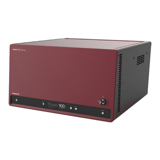
- Page 1 SUPERK FIANIUM White Light Laser PRODUCT GUIDE Item 800-613-01...
- Page 2 PRODUCT GUIDE This guide includes the following NKT Photonics Lasers: SuperK FIANIUM FIU-6 Supercontinuum White Light Laser with or without optional Variable Repetition Rate and approximately 2.2 watts total power SuperK FIANIUM FIU-15 Supercontinuum White Light Laser with or without optional Variable Repetition Rate and approximately 5.5 watts total power...
-
Page 3: Guide Overview
GUIDE OVERVIEW This product guide is intended to provide functional, operational and installation information for the SuperK FIANIUM laser systems. The guide is divided into three sections: • SuperK FIANIUM Description – introduces the laser’s theory and functionality, its features and interfaces, and describes the safety labels and their placement. - Page 4 • Chapter 7 “CONTROL Interface” — Includes descriptions and procedures of all other CONTROL menu and panel items. • Appendices — The guide includes multiple appendices including laser specifications, support contact details, pinout information, accessory descriptions and miscellaneous procedures supporting the laser operation and installation.
-
Page 5: Table Of Contents
CONTENTS Guide overview ........................3 TABLES ........................11 FIGURES ........................13 PROCEDURES ......................15 Section 1 SUPERK FIANIUM DESCRIPTION 1 Laser Description .......................19 Terminology ......................19 Front panel controls .................... 19 CONTROL ......................20 Temperature regulation ..................20 Accessories ......................20 Optical output......................20 Supercontinuum .................... - Page 6 Status button ......................25 Display panel ....................... 25 Power down button .................... 25 Power up button ....................25 Key switch ......................25 Emission button ....................26 Rear panel ........................26 Input and output BNC ports................... 28 Pre-VRR ports ...................... 28 Post-VRR ports ....................
- Page 7 Safety door switch ....................43 Connecting power....................44 Connecting the optical output ................45 Back reflection ..................... 45 Installing the collimator ..................45 Connecting accessories with the external bus ..........46 External bus ......................46 Connecting the external bus ................47 Connecting synchronization ports............... 49 Example synchronization circuit ..............
- Page 8 Operating the laser from the front panel............62 Front panel operations ..................62 Powering ON and OFF the laser ..............62 Adjust the power ....................63 Arming the laser ....................64 Enable emission ....................65 Disable emission ....................65 6 Using CONTROL to Turn ON the Laser ...............67 CONTROL software ....................
- Page 9 Key Updater tool ....................79 Log Downloader ....................80 Extensions overview ..................82 Setting emission power ..................83 Normal mode ......................83 External Feedback mode ..................83 NO emission from the laser ................83 Setting the pulse repetition rate (pulse picker) ..........84 Application Log panel ..................... 84 Device Monitor......................
- Page 10 Troubleshooting...................... 109 Error codes - CONTROL ..................110 Possible fault causes ..................110 Errors - front display panel..................111...
-
Page 11: Tables
TABLES Table 1: Optical specifications................... 20 Table 2: Beam diameter (1/e2 limit) after collimator for three wavelengths ..22 Table 3: Frequency versus VRR factor ................23 Table 4: RS-232 serial port settings ................. 31 Table 5: Status LEDs......................34 Table 6: Chassis labels ....................... - Page 12 Table 29: SPLIT wavelength ranges................100 Table 30: Fiber Delivery System specifications ............101 Table 31: Laser troubleshooting ..................109 Table 32: Errors codes - CONTROL.................110 Table 33: Error codes - front panel ..................111...
-
Page 13: Figures
FIGURES Figure 1: SuperK FIANIUM general view ................ 19 Figure 2: Supercontinuum output of the laser .............. 21 Figure 3: SuperK FIANIUM collimator ................21 Figure 4: Polarization ring mounted on a collimator ..........23 Figure 5: Front panel controls ..................25 Figure 6: Rear panel features and connectors ............ - Page 14 Figure 29: Notifications page – Laser calibration ............62 Figure 30: Boot screen ...................... 63 Figure 31: Power adjusted to 0% before enabling emission ........64 Figure 32: Power adjusted to 100% with emission enabled ........64 Figure 33: Laser is Armed ....................64 Figure 34: Emission enabled ....................
-
Page 15: Procedures
PROCEDURES Procedure 1: Connecting the door interlock circuit ............ 44 Procedure 2: Connecting power ..................44 Procedure 3: Installing the collimator................45 Procedure 4: Turning ON the laser................. 62 Procedure 5: Turning OFF the laser................63 Procedure 6: Arming the laser ..................64 Procedure 7: Enabling emission using the front panel.......... -
Page 17: Superk Fianium Description
SECTION 1 SUPERK FIANIUM DESCRIPTION This section provides a description of the laser and its features. “Laser Description” on page 19 • “Optical output” on page 20 • “Reflection monitor” on page 24 • “Front panel controls” on page 25 •... -
Page 19: Laser Description
2. This guide uses the term, “laser” to refer to all SuperK FIANIUM laser variants. When information related to any specific variant is noted, the model name is specified. The guide may also refer to NKT Photonics as simply NKTP, the two are one and the same. -
Page 20: Control
Optical output CONTROL The laser and its accessories can be managed and configured remotely from a PC using the NKTP CONTROL software. The PC can connect to the laser over either RS232, USB, or Ethernet links. To configure accessories using the same PC, the laser is equipped with an external bus interface which can connect up to eight accessories in a daisy chain configuration. -
Page 21: Spectral Output
Optical output Spectral output Figure 2 shows the spectral power density of the three SuperK FIANIUM series models. Figure 2 Supercontinuum output of the laser Collimator The laser’s optical output uses a collimator (see Figure 3) where the laser beam is emitted from. -
Page 22: Beam Diameter
A small fraction of the beam power is dumped within the collimator. If the thermal contact between the collimator and the mount or receptacle is inadequate, the collimator can become significantly warm. NKT Photonics recommends that you ensure there is thermal contact between the collimator and its mount/receptacle. -
Page 23: Pulse Picker - Vrr (Optional)
Pulse picker – VRR (optional) Figure 4 Polarization ring mounted on a collimator Alignment pin Polarization Ring Note: “Polarization ring” on page 102.“Polarization ring” on page 102 Pulse picker – VRR (optional) The optional factory-installed pulse picker or Variable Repetition Rate (VRR) module is capable of suppressing emission output pulses, reducing the repetition rate of the system. -
Page 24: Using Vrr
Reflection monitor Note: Other possible configurations of repetition rates may be available depend- ing on the laser’s specifications. Contact NKT Photonics for further information. Note: The repetition rate can only be set using either NKTP’s CONTROL manage- ment software or Software Development Kit (SDK). -
Page 25: Front Panel Controls
Front panel controls Front panel controls The front panel controls are highlighted in Figure 5. The panel provides both user controls and a display to directly operate the laser. Figure 5 Front panel controls Power button Power up button Status button Key switch Display panel Emission button... -
Page 26: Emission Button
Rear panel • When turned to OFF, emission cannot be enabled. • When turned to ARMED, emission can be enabled. Emission button Press this button to enable or disable emission. Note: For details on using the front panel controls, see “Front Panel Controls”... - Page 27 Rear panel NIM pulse out (pre-VRR) – BNC Only with VRR option...
-
Page 28: Input And Output Bnc Ports
Input and output BNC ports Input and output BNC ports Pre-VRR ports These interfaces provide synchronization signals that match the pulse output after the optional VRR module. NIM pulse out This signal represents the seed pulse of the laser before the optional VRR module (see Figure 6). -
Page 29: Post-Vrr Ports
Input and output BNC ports Post-VRR ports These interfaces provide synchronization signals that match the pulse output after the optional VRR module. NIM Pulse out The port outputs the same NIM level signal as the pre-VRR “NIM pulse out” on page 28. -
Page 30: Connecting A Pc
Connecting a PC Maximizing the laser warranty The laser’s lifetime is influenced by the total usage of the main amplifier. When the application does not require the laser to be ON continuously. Laser lifetime can be optimized by minimizing the laser ON time. Warning: When this port is connected and the feature turns off the laser booster, the laser seed is still ON and low level Class 4 emission is still present at the laser... -
Page 31: Ethernet Port
Connecting a PC RS-232 serial port settings Table 4 Setting Value Baud Rate 115.2 kbps Data Bits Parity None Flow Control None Transmitted Append LF Text Received Text Mono-spaced Ethernet port This port supports an IPv4 connection over 10/100 Mbps Ethernet. Refer to the Ethernet port setup procedure in the NKTP CONTROL instruction manual. -
Page 32: Configuration And Operation Overview
Configuration and operation overview Configuration and operation overview You can configure and operate the laser from a PC using either: • NKTP’s CONTROL application -or- • a custom software application using NKTP’s SDK. CONTROL NKTP’s CONTROL application is a graphical interface that can manage the laser application from a PC. -
Page 33: External Bus
Configuration and operation overview Interlock safety reset If the enclosure door opens and closes, the laser is shut down by the interlock. When the door is closed again, laser emission can be enabled after resetting the interlock either on the front panel or by software – see “Interlock operation”... -
Page 34: Status Leds
Status LEDs Status LEDs The rear panel houses four status LEDs as described in Table 5. The LEDs indicate the status of the laser’s USB serial connection with a PC. Figure 9 SuperK FIANIUM rear panel status LEDs Table 5 Status LEDs Condition Description ON Green... -
Page 35: Chassis Labels
AVOID EYE OR SKIN EXPOSURE TO DIRECT OR SCATTERED RADIATION CLASS 4 LASER PRODUCT Manufacturing Rear Manufacturing information including address, part and serial number, date NKT Photonics A/S, Blokken 84 DK-3460 Birkerod, Denmark manufactured and regulatory compliance. P/N: S463-125-011 S/N: K0010661 Ver: 01 Manufactured 03-2020 Complies with IEC/EN 60825-1:2014 and 21 CFR 1040.10 and 1040.11 except for... - Page 36 Chassis labels...
-
Page 37: Installing The Laser
SECTION 2 INSTALLING THE LASER This section describes how to install the laser and includes the chapters: • “Mechanical Installation” on page 39 • “Connecting the Laser” on page 41 • “Connecting External Control” on page 53... -
Page 39: Mechanical Installation
Mechanical Installation SuperK FIANIUM lasers generate a substantial amount of heat that must be dissipated. To dissipate the heat, the SuperK FIANIUM is available in three different chassis versions defined by their temperature regulation system. This chapter provides information on how to mechanically install the laser with focus on ensuring optimal regulation of the laser’s temperature. -
Page 40: Installing The Laser Chassis
Installing the laser chassis Installing the laser chassis The laser should be located so that the fan intake and exhaust vents are not obstructed. The laser is equipped with four mounting feet and can be placed on any suitable level and stable surface capable of supporting the laser’s weight. Figure 11 SuperK FIANIUM installation Left Panel RIght Panel... -
Page 41: Connecting The Laser
Connecting the Laser Before operating the laser, follow the procedures in this chapter to ensure its correct and safe operation. For information on how to connect: • the safety interlock – see “Connecting the safety interlock” on page 42 • Power –... -
Page 42: Connecting The Safety Interlock
Connecting the safety interlock Connecting the safety interlock To comply with safety regulations and help provide a safe operating environment, the safety interlock of the laser must be connected to a switch activated by an access door to the laser’s enclosure. When the connected switch is opened by the door, it opens the interlock circuit which turns off laser emissions. -
Page 43: Safety Door Switch
Interlock Reset Caution: Do not short-circuit the Interlock input. Short-circuiting the interlock cir- cumvents safety regulations and NKT Photonics does not take liability for any in- juries or damage caused by doing so. Caution: The switch connected to the interlock must be of an approved type. Fur- ther, the switch must be installed in a manner so that its operation cannot be fixed in the open state using a tool to defeat its operation. -
Page 44: Connecting Power
Connecting power Procedure 1 Connecting the door interlock circuit Action Install a switch that opens when the door accessing the laser enclosure is opened. The switch must comply with local regulations. Connect the switch to the prewired interlock plug using insulated wire. The wire gauge should be at a minimum 26 AWG with a maximum length of five meters. -
Page 45: Connecting The Optical Output
Connecting the optical output Caution: Ensure you use an approved cord set when supplying AC mains power. The cord set must be suitable for the laser’s power ratings and be approved by your regional electrical safety regulations. Caution: The cord’s appliance coupler (the connector at the laser; not the wall plug) must be a configuration that mates with an EN 60320/IEC 320 appliance in- let. -
Page 46: Connecting Accessories With The External Bus
Connecting accessories with the external bus Figure 14 Inserting the collimator into a holder Figure 15 Collimator inserted into a SuperK accessory receptacle Figure 16 Collimator inserted in a holder receptacle Connecting accessories with the external bus External bus The External Bus port is a digital bus interface and 12 volt supply for attached accessories. -
Page 47: Connecting The External Bus
Connecting accessories with the external bus subset of the RS-485 protocol. The bus is also made up of other signal lines, including a logic output pin representing laser emission and an extension of the laser’s interlock circuit. Connecting the If no accessories are used with the laser, place the supplied bus defeater onto external bus the laser’s External Bus port. -
Page 48: Figure 18 External Bus Circuit - With No Accessories Used
Connecting accessories with the external bus Figure 18 External bus circuit - with no accessories used SuperK FIANIUM External Bus Connector Bus Defeater Figure 19 External bus circuit - with multiple accessories in a daisy chain SuperK FIANIUM SuperK Accessory A External Bus Connector SuperK... -
Page 49: Connecting Synchronization Ports
Connecting synchronization ports Connecting synchronization ports The SuperK FIANIUM can supply up to five synchronization signals. The signals can synchronize external devices with the laser pulse at two stages within the laser. If the laser is fitted with a VRR (pulse picker) module, all five signals are available. -
Page 50: Gate Out
Connecting synchronization ports Figure 21 Example NIM pulse circuit Pulsed emission SuperK FIANIUM NIM Pulse NIM level pulse (post VRR) (RG223 Cable) Synchronizer Sensor control Subject target Sensor output Sensor Gate out The Gate out port supplies a digital signal synchronized with the pulse after the VRR module (pulse picker). -
Page 51: Nim Pulse
Connecting synchronization ports Table 12 Pulse out ports specification Item Description Cable Type Use RG223 type or similar double shielded cable 3M Connector Termination Impedance NIM pulse The pre and post-VRR NIM pulse ports output a NIM level electrical signal representing the laser’s pulsed output. - Page 52 Connecting synchronization ports...
-
Page 53: Connecting External Control
Connecting External Control This chapter includes the configuration details for: • “External feedback” – describing how to connect a feedback circuit to the laser to stabilize the output power level. • “Booster ON/OFF”– describing how to connect an external logic signal to the laser to turn ON or OFF the laser’s booster. -
Page 54: Booster On/Off
Booster ON/OFF Booster ON/OFF Using the booster feature, you can apply a TTL or CMOS level logic signal at the Booster ON/OFF port to enable or disable laser emission. When the feature is enabled, a logic high applied at the port enables laser emission with a fast rise time. -
Page 55: Operating The Laser
SECTION 3 OPERATING THE LASER This section describes how to manage and operate the laser and includes the chapters: • “Front Panel Controls” on page 57 • “Using CONTROL to Turn ON the Laser” on page 67 • “CONTROL Interface” on page 73... -
Page 57: Front Panel Controls
Front Panel Controls Overview The front panel features an OLED display, control buttons, and an interlock keyswitch. You can use the display and buttons to: • Enable and disable emission. • Adjust the laser output power level from 0 to 100%. •... -
Page 58: Display
Display Display The display can show four page types. The pages are listed below in Table 17; for more details follow the link in the right column. Table 17 Display pages Page type Function Operation page on Displays current operational Operation settings page 58... -
Page 59: Table 18 Emission Status
Operation page Figure 26 Operation page Power level 0-100% External mode Repetition rate Emission status The Operation page shows the following fields: • Power – The laser’s configured level of output emission power. RANGE: 0 to 100% • External mode – External mode is only displayed when the laser is configured to use an external input signal to modulate the output pulse. -
Page 60: Connected Modules Page
Connected modules page Emission status field Message Meaning Interlock OFF due to the keyswitch in the OFF Key off position Firmware update in progress Updating System calibration in progress Calibrating Keyswitch - Armed, Interlock and door switch circuits - closed Connected modules page The Connected modules page (Figure... -
Page 61: Error Page
Error page Error page If an error occurs, the system display shows a page with an error message. The error message includes: • Module address – System module address • Internal address – Address for NKTP use only • Error code – Code number assigned to the error for a module •... -
Page 62: Clearing The Notification Page
Ensure all personnel are notified of the laser’s operating area and that the beam path is safely contained. For fur- ther information refer to the NKT Photonics document: SuperK FIANIUM Safety, Handling and Regulatory Information... -
Page 63: Adjust The Power
Operating the laser from the front panel 3. A boot screen (Figure 30) with the NKT Photonics logo is displayed until the system is ready for operation. 4. If the laser boots correctly, the laser’s operation page appears (see “Operation page” on page 58) and the laser is ready for operation. -
Page 64: Arming The Laser
Operating the laser from the front panel Figure 31 Power adjusted to 0% before enabling emission Warning: Only adjust the power to a higher level when you are certain the beam path is safe and all personnel in the operating area are aware of the danger. The laser is a CLASS 4 laser and emits hazardous emission. -
Page 65: Enable Emission
Operating the laser from the front panel Enable emission Procedure 7 Enabling emission using the front panel Press the front panel Emission button once. The emission status field changes from Armed to Emission ON. Calibration The laser auto-calibrates when emission is enabled from the disabled state. Figure 34 Emission enabled Warning: Only enable emission when you are certain the beam path is safe and... - Page 66 Operating the laser from the front panel...
-
Page 67: Using Control To Turn On The Laser
Using CONTROL to Turn ON the Laser The SuperK FIANIUM laser can be managed using NKTP CONTROL software installed on a PC. This chapter focuses on: • How to obtain and install the CONTROL software • Connect a PC using USB connectivity •... -
Page 68: Procedure 9 Connecting Control To The Laser
Connecting power on page 44. Connect the PC to one of the available ports. Launch the CONTROL software by either: • clicking on Windows – Start – Programs – NKT Photonics –CONTROL – or – • double clicking the CONTROL shortcut on the desktop The CONTROL window opens. -
Page 69: Controlling The Laser Emissions
Controlling the laser emissions Controlling the laser emissions Safety Before you turn ON the laser emission, ensure that you are completely familiar and follow all safety information and recommendations stated within this document and the document: SuperK FIANIUM Safety, Handling and Regulatory Information Warning: You must follow all safety regulations required by the location where the laser will be operated. -
Page 70: Turning On The Laser
Controlling the laser emissions Turning ON the Check you have prepared the laser according to “Preparation” on page 69. Then laser follow the steps in Procedure 10 to enable laser emission using CONTROL. Procedure 10 Enabling emission with CONTROL Action On the front panel of the laser, turn the key switch on the laser’s front panel to the Armed position. -
Page 71: Turning Off The Laser Emission
Controlling the laser emissions Turning OFF the Follow the steps in Procedure 11 to turn OFF the laser emission. laser emission Procedure 11 Disabling emission with CONTROL Action Disable the laser emission by clicking on the Emission ON/OFF button. The Emission button light turns from RED (ON) to green (OFF). - Page 72 Controlling the laser emissions...
-
Page 73: Control Interface
CONTROL Interface CONTROL overview The CONTROL user interface includes multiple panels and a selection of menu drop down items in the upper left corner. Using the Window drop down menu, you can add or remove displayed panels. The panels can also be dragged within the main window or into separate windows. -
Page 74: Relocating Panels
CONTROL overview Relocating panels The panels displayed by CONTROL can be dragged to any location within the main interface or into a separate floating panel. Procedure 12 describes how to move a panel: Procedure 12 Relocating panels Action Click and hold the top title bar of the panel. While holding the left mouse button down drag the panel to another location in the main window. -
Page 75: Toggling Panels
CONTROL overview Toggling panels Use the Menu > Window drop down menu to check and uncheck panels to be viewed. Figure 38 Toggling panel visibility Check the panels to display them Note: Clicking the X in the upper right corner of any panel will also close it. Connecting to the When CONTROL is launched, the Welcome panel is displayed as in Figure... -
Page 76: Status Panel
Status Panel Status Panel The Status Panel provides status indicators, error messages, emission control function and a CONTROL settings menu. Figure 40 Status Panel Status Indicators The panel displays the following indicators: Interlock Indicates the status of the Interlock circuit and whether emissions can be turned on or not. -
Page 77: System Info
Control settings • ON RED – There is a fault, laser emissions are shutdown and cannot be turned ON. A fault message will be displayed when this indicator turns ON RED: Fault Message Action Interlock opened while emission on a) Cycle the key switch to Off and then Armed b) Close the external interlock circuit Watchdog timeout Reconnect NKTP CONTROL and reset the interlock... -
Page 78: Watchdog
Control settings Watchdog As an added safety feature, the watchdog will automatically disable laser emission if communication with CONTROL is lost. The feature can be enabled or disabled and has an adjustable timeout. When communication is lost with the laser, the laser watchdog timer counts down from the timeout setting value (1 to 255 seconds). -
Page 79: Control Menu
CONTROL menu Figure 44 View Check to display Input LCD panel text to display CONTROL menu There are five drop down menus in the main control window as highlighted in Figure 45. Click on the items in the menu to reveal the drop down menus. Figure 45 Menu items Menu Item Function... -
Page 80: Log Downloader
NKT Photonics support personnel. Log Downloader If your laser requires support from NKT Photonics, our support engineers may request that you send the log files collected by the laser. You can use the log downloader tool to save the laser log files to your CONTROL PC. -
Page 81: Procedure 14 Using The Log Downloader
CONTROL menu Procedure 14 Using the Log Downloader Action Open the Tools menu and click on Log Download to start the Log Downloader tool. The tool displays all connected modules with log capability. To decrease the download time of the module log files, CONTROL continuously collects module log data and stores this log data in a local database on the... -
Page 82: Extensions Overview
This tool is used to view the installed extensions (plugins) that are included with overview CONTROL. The extensions are found in the following folder: C:\Program Files (x86)\NKT Photonics\NKTP CONTROL\Plugins To view the extensions, open the Tools menu and click on Extensions Overview. The Extensions Overview window will be launched as shown in... -
Page 83: Setting Emission Power
Setting emission power Setting emission power Using the control panel, the SuperK FIANIUM the control panel can be configured to operate in two modes by clicking on the Operating mode drop down menu shown in Figure 47. Each mode determines how the output emission power is set. -
Page 84: Setting The Pulse Repetition Rate (Pulse Picker)
Application Log panel The Application Log panel displays and logs the communication of status messages. The log can be used to debug connection issues between CONTROL and NKT Photonics devices. The panel displays and timestamps the following types of log messages:... -
Page 85: Device Monitor
Device Monitor • Port Scans • Discovered Devices • Closed Communication Ports The panel includes three buttons in the upper left corner. You can use the buttons to clear, save or print the log. Click on the cross in the upper right corner of the Application Log window to close the Application Log. - Page 86 Device Monitor Parameter Description Status bits The actual status bits read from the connected module. Error code The actual error code read from the connected module. Access Protected/Locked status of the module. FW Ver. The device module’s firmware release date. Module Serial The serial number of the device module.
-
Page 87: Appendices
APPENDICES The appendices include: Appendix A on page 89 Specifications • Appendix B on page 91 Service and Support • Appendix C on page 93 External Bus Pinout • Appendix D on page 95 Accessories • Appendix E on page 103 Control Software •... -
Page 89: A Specifications
Specifications Table 21 Interfaces RS-232 serial COM - 9 Pin D-Sub Female Connector PC and micro processor interfaces USB 2.0 - Type B Female Connector External Feedback: BNC 0 to 4.1 V analog input – power stabilization External Pulse Control Booster ON/OFF: BNC 0 to 5V TTL/CMOS input –... -
Page 91: B Service And Support Information
Service and Support Information Servicing the laser The SuperK FIANIUM series lasers have no user serviceable components. In case of malfunction, contact NKT Photonics using the support channels in section “Support contact details”. End of line safety tests according to EN61010-1 Annex F are performed on all Laser chassis. - Page 92 Support contact details...
-
Page 93: C External Bus Pinout
External Bus Pinout Table 24 External bus pinout Name Description Not connected RS485- Negative (inverted) RS485 data signal Interlock loop+ Positive connection of the safety interlock loop. Connect pin 3 to pin 4 Interlock loop- to enable laser emission. Interlock loop- Negative connection of the safety interlock loop. -
Page 95: D Accessories
Accessories This appendix provides a brief overview of the accessories available for your laser. Table 25 lists the accessories and their functions and provides a link to descriptions of the SuperK FIANIUM advanced accessories. Table 25 SuperK FIANIUM accessories Advanced accessories Function Part number VARIA... -
Page 96: Superk Varia
SuperK VARIA SuperK VARIA The VARIA accessory acts as a bandpass filter when connected to the collimator of the SuperK FIANIUM laser. A portion of the beam from the SuperK FIANIUM is diverted to the VARIA’s bandpass filter which removes the light wavelengths that fall outside a variable wavelength range. -
Page 97: Superk Select
SuperK SELECT SuperK SELECT A SuperK SELECT accessory can be fitted to extract multiple specific light wavelengths from the broadband spectrum output of the SuperK FIANIUM laser. The SELECT accessory uses Acousto-optic Tunable Filter (AOTF) technology which uses a tellurium dioxide crystal that diffracts the desired beam wavelength. The specific wavelength diffracted by the crystal is tuned by applying an RF signal to it. -
Page 98: Table 27 Select Aotf Types
SuperK SELECT Table 27 SELECT AOTF types AOTF type Wavelength range (nm) Bandwidth (nm) UV-VIS 400-650 1.8-8.5 VIS (1x) 430-700 0.5-1.85 VIS (4x) 450-700 2.5-8.5 VIS-nIR 500-900 3.5-14 nIR1 640-1100 1,5-5 nIR2 800-1400 2.6-9.6 1100-2000 6.4-19.8 As noted earlier, the tuned beam which is defracted from a SELECT crystal filter will also include a number of n’th order side lobes. -
Page 99: Superk Lltf
SuperK LLTF SuperK LLTF The Laser Line Tunable Filter (LLTF) Contrast accessory provides a tunable and extremely narrow bandpass filter with out-of-band (OOB) suppression in the order of 60 dB. The filter can be continuously tuned over the entire spectrum of the supercontinuum laser, converting the wide band beam to a finely tuned picoseconds laser. -
Page 100: Superk Split
SuperK SPLIT SuperK SPLIT Use the SuperK SPLIT to divide the SuperK FIANIUM emissions into two separate spectral outputs. The SPLIT is a passive filter and it is available in two standard models where the spectral outputs are configured as either: •... -
Page 101: Superk Connect And Fiber Deliver System
Figure Figure 59 SuperK Fiber Delivery System using a CONNECT The CONNECT and its fiber couplers are part of NKT Photonics Fiber Deliver System (FDS). It combines high coupling efficiency with power handling up to 500 mW over a spectrum from 400 to 2000 nm. It can be disconnected and reconnected to any photonic system without needing realignment of the coupling. -
Page 102: Polarization Ring
Polarization ring Polarization ring This is a spacer and alignment ring that fits onto the laser collimator. It MUST be used when inserting the collimator into an accessory optical input receptacle. The ring has an alignment pin which aligns the polarization of the laser emission properly with the accessory optics. -
Page 103: E Control Software
Control Software Installing CONTROL Download the software from: https://www.nktphotonics.com/lasers-fibers/support/software-drivers/ Follow the steps in Procedure Procedure 15 Installing CONTROL Action On the PC, launch the installer package and then click the Installer Run button. The installation wizard appears. Click Next to continue. - Page 104 Installing CONTROL Action Accept to use the default installation directory or select another directory by clicking the Browse button. Click Next to continue. Uncheck the components you do not require. By default, all components will be installed. Click Next to continue. Read the End-User License Agreement, and select: “I accept the license.”.
- Page 105 Installing CONTROL Action The wizard will create a start menu folder with program short-cuts. Use the default name or enter a new name for the folder. Click Next to continue. Check the box to create a desktop shortcut to access Control.
- Page 106 Installing CONTROL Action Click Install to install NKTP CONTROL software on your Click Cancel if you want to abort the installation.. The wizard displays a progress meter for the installation. Note: a normal install should only take a few seconds. Click Next to install the UART drivers for the PC USB port.
- Page 107 Installing CONTROL Action The drivers will be installed. The Silicon Labs drivers is installed successfully. Click Finish to end the installation wizard. CONTROL is now installed. Check the Run box to launch CONTROL when the Finish button is clicked. Click Finish.
- Page 108 Installing CONTROL...
-
Page 109: F Troubleshooting And Errors
Troubleshooting and Errors Troubleshooting Table 31 Laser troubleshooting Symptom Possible cause(s) Action Laser Disabled Interlock signals shorted to 1. Disconnect the power to the laser. Locate and remove the ground. interlock circuit short to ground. 2. Turn ON the SuperK FIANIUM system and reset the interlock with the key switch. -
Page 110: Error Codes - Control
Set to 0% power. (Slider set all the way to the left.) 2. Enable the laser by clicking the Emission button ON. 3. Slowly increase power to 100%. If the problem is not resolved contact NKT Photonics. See Appendix Other codes: Contact NKT Photonics. -
Page 111: Errors - Front Display Panel
Errors - front display panel Errors - front display panel Table 33 Error codes - front panel Module Error address number Error message Interlock open Contact NKTP support Contact NKTP support Temperature out of range Contact NKTP support Contact NKTP support Laser needs to calibrate. - Page 112 Errors - front display panel Module Error address number Error message Enable emission. If error persists, contact NKTP. Enable emission. If error persists, contact NKTP. Enable emission. If error persists, contact NKTP. Enable emission. If error persists, contact NKTP. Enable emission. If error persists, contact NKTP. Enable emission.
- Page 113 SuperK FIANIUM Product Guide Revision 1.4 01-2021 W-10456...
Need help?
Do you have a question about the SuperK FIANIUM FIU-6 and is the answer not in the manual?
Questions and answers