Table of Contents
Advertisement
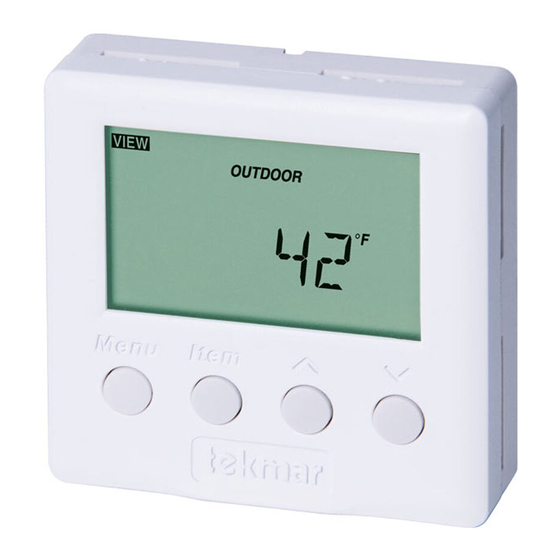
Thermostat 508
Table of Contents
Display / Keypad Operation ............ pg 1
Display Symbols ............................. pg 2
General ........................................ pg 2-3
Sequence of Operation................pg 3-4
Installation ....................................pg 4-5
Wiring Examples .......................... pg 6-7
User Interface ................................. pg 8
Display / Keypad Operation
The thermostat's display has four distinct fields. These fields are the Menu field, the Item
field, the Number field and the Status field. The four buttons on the face of the thermostat are
used to navigate through the menus and items to view and / or adjust the desired settings.
Displays the
current
menu
Displays the current
status of the
thermostat's inputs,
outputs and operation
- Data Brochure
1 of 12
Menus ........................................ pg 8-10
View Menu ................................ pg 8
Adjust Menu ............................ pg 9
Schedule Menu ...................... pg 10
Error Messages ........................... pg 10
Warranty ....................................... pg 12
Displays an abbreviated
name of the selected item
AWAY
Selects Menus, Items
and adjusts settings
© 2010
D 508
05/10
Displays the current value
of the selected item
D 508 - 05/10
Advertisement
Table of Contents

Related Manuals for Tekmar D 508


Summary of Contents for Tekmar D 508
-
Page 1: Table Of Contents
AWAY Displays the current value of the selected item Displays the current status of the thermostat's inputs, outputs and operation Selects Menus, Items and adjusts settings 1 of 12 © 2010 D 508 - 05/10... -
Page 2: Display Symbols
The temperature being read by the slab sensor is used in the calculations of the ON time for the Heat relay and allows the thermostat to operate the slab between the slab minimum and slab maximum settings. © 2010 D 508 - 05/10 2 of 12... -
Page 3: Sequence Of Operation
During light heating loads, overheating can occur due to the minimum slab temperature requirements. During heavy heating loads, the maximum slab temperature setting limits the ON time of the Heat relay. In this situation, underheating can occur. 3 of 12 © 2010 D 508 - 05/10... -
Page 4: Installation
Check the contents of this package. If any of the contents are missing or damaged, please contact your wholesaler or tekmar sales representative for assistance. Type 508 Includes: • • One Thermostat 508 • Data Brochure D 508 • • User Brochure U 508 STEP TWO REMOVING THE FRONT COVER Place a screwdriver or similar object into the small slot located in the top of the thermostat. - Page 5 Pivot the front cover around the bottom hinges and push the top against the mounting base until it snaps firmly in place. Pivot front cover around bottom hinges Align hinges on bottom of front cover 5 of 12 © 2010 D 508 - 05/10...
-
Page 6: Wiring Examples
Wiring Examples Wiring to a tekmar Wiring Center 315 or 316 115 V (ac) 24 V (ac) Sensor Wires 944-02 Thermostat 508 One Stage Heat Power: 24 V ±10% 50/60 Hz 1.5 VA. Relay: 24 V (ac) 2 A Class 2... - Page 7 FCC Part 15 Access level 24 V POWER Installer User Not used Switching Relay Sensor Zone 1 Zone 2 Zone 3 Class 2 Transformer Zone Pump 115 V (ac) Auxiliary Sensor 7 of 12 © 2010 D 508 - 05/10...
-
Page 8: User Interface
The current temperature at the outdoor sensor. (SENS must be set to OUT.) SLAB The current slab temperature. (Must have an active slab sensor.) The MIN segment is displayed when running at Slab Minimum. © 2010 D 508 - 05/10 8 of 12... -
Page 9: Adjust Menu
Determines the number of cycles per hour for the heating equipment. This item is only available in the Installer access level. Au, 2 to 12 UNITS The units of temperature used to display the items. °F, °C 9 of 12 © 2010 D 508 - 05/10... -
Page 10: Schedule Menu
The auxiliary sensor is open circuit. Locate and repair the problem as described in the appropriate sensor brochure. After the fault is corrected, press any button to clear the error message. © 2010 D 508 - 05/10 10 of 12... - Page 11 Notes 11 of 12 © 2010 D 508 - 05/10...
-
Page 12: Warranty
Prod- uct was not installed in compliance with tekmar’s instructions and / or the local codes and ordinances; or if due to defective installation of the Product; or if the Product was not used in compliance with tekmar’s instructions.
Need help?
Do you have a question about the D 508 and is the answer not in the manual?
Questions and answers