Advertisement
Instructions for setting up your Megasquirt-2 ECU.
This version of the documentation applies to the Megasquirt-2 range of products which includes:
MS2 on V3.0 or V3.57 mainboard;
•
MicroSquirt;
•
Products derived from the MicroSquirt Module (e.g., DIYPNP and MSPNP2).
•
and running firmware MS2/Extra 3.4.x. (See section 2.10.3 for more detail on version numbers.)
Not covered:
Megasquirt-2 products running "Bowling and Grippo" firmware.
•
Megasquirt-2 products on a V2.2 mainboard.
•
MegaSquirt-1;
•
EMS-Pro
•
MegaSquirt-3;
•
MS3-Pro or products using MS3-Pro module
•
MS3-Gold
•
Megasquirt-2 Setting up
Megasquirt-2 Product Range
MS2/Extra 3.4.x
Dated: 2019-01-11
(c) 2014-9 James Murray
Advertisement

Summary of Contents for MegaSquirt 2
- Page 1 Megasquirt-2 Setting up Megasquirt-2 Product Range MS2/Extra 3.4.x Dated: 2019-01-11 Instructions for setting up your Megasquirt-2 ECU. This version of the documentation applies to the Megasquirt-2 range of products which includes: MS2 on V3.0 or V3.57 mainboard; • MicroSquirt; •...
-
Page 2: 0: Quickstart Guide - In Brief
4. Connect MAP hose to full vacuum source. (Speed Density only.) 5. Install TunerStudio and Megalogviewer software onto you computer. 6. Connect your Megasquirt to a 12V fused supply either in the vehicle or on the bench. 7. Get the serial comms set up. -
Page 3: Table Of Contents
Megasquirt-2 Setting Up 0:Contents 0: Contents Table of Chapters 0: QuickStart Guide - in brief....................2 0: Contents..........................3 1: Introduction........................9 2: QuickStart Guide - expanded..................13 3: Tuning the engine......................45 4: Advanced topics......................64 5: Troubleshooting.......................85 6: Appendix A: Firmware upgrade notes................96 7: Appendix B: Fuel calculations..................103 8: Appendix C: Megasquirt Glossary of Terms..............105... - Page 4 2: QuickStart Guide - expanded..................13 2.1 Buy or build your Megasquirt!...................13 2.2 Select and assemble your fuel and ignition systems..........13 2.3 Setup your vehicle wiring harness (loom) ensuring it is fused.........13 2.4 Connect MAP hose to full vacuum source..............13 2.5 Install TunerStudio and Megalogviewer..............13 2.6 Power up your ECU....................13...
- Page 5 2.13.5 Idle Valve......................33 2.13.6 Other inputs/outputs..................34 2.13.7 Gauge/Setting Limits..................34 2.13.8 Power Cycle Required..................34 2.13.9 Configuration Error..................35 2.14 Use the test mode to confirm injectors and coil(s) are functioning......36 2.14.1 Injector testing....................36 2.14.2 Coil testing.......................36 2.14.3 Fuel pump testing....................37 2.14.4 Idle Valve Testing.....................37 2.14.4.1 Using the test mode to determine stepper homing steps........38...
- Page 6 3.4.4.3 VE trim table (MAF)....................52 3.4.4.4 MAFload.........................53 3.4.5 Tuning fuel - ITB....................53 3.4.5.1 ITB Load TPS Switchpoint Curve................54 3.4.5.2 ITB Load at TPS Switchpoint Curve...............54 3.4.5.3 AFR Table (ITB)......................54 3.4.5.4 VE Table (ITB)......................54 3.4.5.5 ITB technical......................54 3.4.6 Basic acceleration enrichment (AE) tuning............56 3.4.6.1 Main accel enrich settings menu................57...
- Page 7 5.4.1.1 Windows device.......................92 5.4.1.2 Mac OS X device....................92 5.4.1.3 Linux device......................93 5.4.2 Loopback test for serial or USB-serial cable.............93 5.4.3 Loopback test to Megasquirt board (not Microsquirt)........94 5.4.4 Comms test to Megasquirt / Microsquirt............94 6: Appendix A: Firmware upgrade notes................96 6.1 Firmware versions....................96...
- Page 8 7.2 Speed Density......................103 7.3 B.2 Alpha-N (pure)....................103 7.4 Alpha-N (hybrid)......................103 7.5 %baro........................104 7.6 MAF........................104 8: Appendix C: Megasquirt Glossary of Terms..............105 9: Appendix D: Text-based firmware loader..............112 9.1 Windows / general....................112 9.2 Mac / Linux......................116 9.3 Steps after loading firmware...................116 10: Revision history......................117...
-
Page 9: 1: Introduction
Power probe 1.3 How to use the manuals The documentation for the Megasquirt-2 product family is split across a number of manuals. The Setting up, TunerStudio and MegaLogViewer Guides are general and apply to all Megasquirt-2 products. The Hardware manuals focus in detail on just one product to keep the specifics clear. Be sure to check that you are using... -
Page 10: Products Covered
1.4 Products Covered The Megasquirt-2 range of products all use the same processor at the core but are packaged differently for different markets. The core configuration and setup is almost identical. There are minor differences in ignition settings and wiring. -
Page 11: Ms2 On A V3.57 Mainboard
This combination uses a factory-assembled V3.57 mainboard and a Megasquirt-2 daughtercard. This is aimed at the customer that wants a cased Megasquirt-2 but prefers to buy pre-assembled. The V3.57 mainboard has less flexibility for future extension and modification. By customising, more inputs and outputs are available than the Microsquirt. -
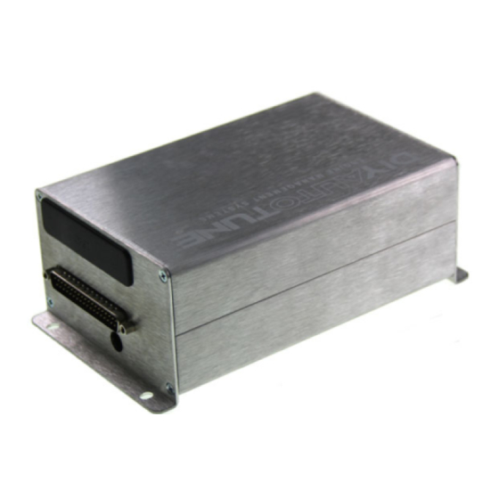
Page 12: Microsquirt-Module
The Microsquirt is a fully factory-assembled ECU and uses an automotive grade AMPSEAL connector. This is aimed at the cost conscious customer that wants a Megasquirt-2 type product in a professional case. There is no provision for internal modification and low impedance injectors are not directly supported. -
Page 13: 2: Quickstart Guide - Expanded
2.1 Buy or build your Megasquirt! Before you can begin your installation, you need to have purchased your Megasquirt/Microsquirt. In the case of a kit you need to assemble it. Kit assembly is covered in the Hardware Manual for your product. - Page 14 Megasquirt-2 Setting Up 2:QuickStart Guide - expanded MS2 serial port. Microsquirt serial cable. Standard DB9 male connector on computer. Standard DB9-DB9 straight through serial cable. Computer USB socket (c) 2014-9 James Murray 2019-01-11 Page 14/117...
- Page 15 Megasquirt-2 Setting Up 2:QuickStart Guide - expanded Typical USB-serial adapter Before inserting a USB-serial adapter, follow the manufacturers' instructions for driver configuration. (Windows only) Having found your true serial port or plugged in your USB-serial adapter, it is desirable to opening up Device Manager and identify the COM port number.
-
Page 16: Turn Off "Hide Extensions For Known Files Types" (Windows Only)
Should you encounter problems getting your serial connection working, refer to the fault finding section. 2.8 Turn off "Hide extensions for known files types" (Windows Only) Windows has a feature to hide part of the filename. It is strongly advised that this is disabled to prevent confusion. -
Page 17: Install The Firmware If Required
Your web browser may have a "show in folder" option for the download or open up the file explorer and find it. You are looking for a file similar to ms2extra-release-3.4.2.zip (If you don't see the ".zip" on the end, re- read section 2.8.) Open up this zip file to see the contents, it includes the firmware files and default tune files (i.e. -
Page 18: Get Your Tuning Computer To Talk To The Ecu
Start TunerStudio ii. Create a new project. (More details on this step can be found in the TunerStudio Reference manual in section 2.1) From the Start Screen select File > New Project or from the Main Screen select File > Project > New Project. - Page 19 Megasquirt and its firmware version. If successful it will list your Megasquirt, firmware version and baud rate. Check to see that these appear to match your Megasquirt and then click “Accept” to continue. If the “Detect Device” screen reports “No controller found” check the connection between your computer and your Megasquirt and ensure that your Megasquirt has power and try again.
- Page 20 For information: the old text-based firmware loader is covered in section 9. iv. Other / Browse This method is recommended only if TunerStudio is not able to detect your Megasquirt, or if you are using a beta version of the firmware.
- Page 21 3. mspnp2.ini – used for the DIYautotune MSPNP2. 4. microsquirt-module.ini – used for the generic Microsquirt Module. (If you have purchased a proprietary Megasquirt-2 product based on the Microsquirt Module it is worth contacting the manufacturer to confirm which firmware/ini version you should use).
- Page 22 Megasquirt-2 Setting Up 2:QuickStart Guide - expanded Generally these can be left alone. Click Next. vii. Dash Click Finish. The standard dash should display. (c) 2014-9 James Murray 2019-01-11 Page 22/117...
-
Page 23: Tunerstudio Basics
Megasquirt-2 Setting Up 2:QuickStart Guide - expanded 2.10.1 TunerStudio basics Be sure to read Section 1.5 in the TunerStudio Reference Guide - this covers the user interface in detail. Two items are worthwhile repeating here. Throughout the software you will find Tooltips - clicking on the [?] will bring up explanatory text. -
Page 24: Firmware, Tunerstudio, Tune Files (Msq) - What's All That
The tune file (MSQ file) is a copy of your engine's tune, saved onto your tuning computer. Typically you can load in tunes that were saved from older versions of Megasquirt firmware. The file format is designed to allow conversion of the data and a relatively smooth transition. -
Page 25: Tunerstudio Version
TunerStudio title bar. 2.10.3.3 TunerStudio Version At time of writing, the current TunerStudio (TS) version is 2.6.19. Most of the tuning user interface (menus etc.) are in fact determined by the firmware version. The TunerStudio version may impact the use of tuning features such as auto-tune or the dashboard displays. -
Page 26: Calibrate Map/Baro
2:QuickStart Guide - expanded To calibrate the throttle position sensor do the following: 1. Ensure that your Megasquirt is connected and the engine is not running (i.e., KOEO). 2. Ensure that the throttle is closed; 3. Click the “Get Current” button to the right of “Closed throttle ADC count”;... -
Page 27: Unlock Calibrations
Ensure that the calibrations are re-locked once you have made your calibrations. 2.11.4 Calibrate CLT and MAT sensor Megasquirt ECUs are supplied loaded with the correct calibrations for GM temperature sensors. You only need to go through this calibration process if you are using different sensors. -
Page 28: Calibrate Afr Table (O2 Sensor)
Bias Resistor Value (Ohms) This is 2490 ohms unless you or your vendor have changed the resistors inside the Megasquirt. Temperature Settings (°C or °F) Again, if you have selected one of the common sensors these values should be set for you. If you are using a custom sensor enter the three measured temperature and resistance value pairs. -
Page 29: Lock Calibrations
2.11.6 Lock calibrations Open Tools > Un/Lock calibrations, select Locked and then Close. 2.12 Check all sensor inputs are reading sensibly in TunerStudio. Now that your have communication and have the sensor inputs calibrated, it is time to check that the sensor inputs make sense. -
Page 30: Set The Base Settings
The first rule of tuning is that you do not want to tune from a blank file. You can either connect to the Megasquirt and automatically retrieve the tune on it or open an existing tune file, but stop if you see this message: This means that you have no tune loaded. -
Page 31: Control Algorithm Choice
Megasquirt-2 Setting Up 2:QuickStart Guide - expanded 2.13.1 Control Algorithm choice There are a number of different methods to estimate the airflow into an engine. These depend on the available sensors and their accuracy at predicting flow. Use Speed-density unless you have a good reason to choose otherwise. -
Page 32: Engine And Sequential Settings
Megasquirt-2 Setting Up 2:QuickStart Guide - expanded 2.13.2 Engine and Sequential settings The most critical settings are on the left. Complete the Control Algorithm through to Injector size settings. If unsure, leave alone! Then click on the "Required Fuel" button to calculate the "ReqFuel" number. -
Page 33: Ignition Setup
Wiring and configuring your ignition setup covers the tach input (how Megasquirt gets an RPM signal) and how the ignition coil or coils are controlled. The exact details depend on which Megasquirt-2 product you have, so this section is covered in the Hardware Manual for your product. -
Page 34: Other Inputs/Outputs
Stepper idle users need to configure the number of homing steps - this is covered in the section on idle valve testing - 2.14.4.1. For now, set the homing steps to 250 and ensure that all values in the warmup curve are less than 180. -
Page 35: Configuration Error
1. Read the message - it tells you what to do. 2. If you have a pin conflict, take a look at Basic/Load Settings -> Feature List Showing I/O Pins you should be able to spot where you have set two features to use the same connection. -
Page 36: Use The Test Mode To Confirm Injectors And Coil(S) Are Functioning
The injector test mode can be used both to confirm the injectors are wired correctly and to use the Megasquirt as a controller for an injector test bench. If your injectors are fitted to the engine, you must not run the test mode with fuel pressure or you will fill your engine with fuel! Remove the fuse from your fuel pump and de-pressurize the line first. -
Page 37: Fuel Pump Testing
Megasquirt-2 Setting Up 2:QuickStart Guide - expanded Click Start • With wasted spark or coil-on-plug installs, make sure that "Spark A" operates the spark plug for cyl#1. Note that coil testing will not work with EDIS, TFI, HEI7/8 or GMDIS as the external module controls the coils internally. -
Page 38: Using The Test Mode To Determine Stepper Homing Steps
Here is an example of a fixture used to measure stepper operation on the bench, although very few users will need one of these. 2.14.4.1 Using the test mode to determine stepper homing steps In the initial setup, rough values were given for the homing steps and maximum number of steps to use in the curves. -
Page 39: Check For Crank/Cam Tach-In Signals
ECU will lose track of where the valve is. This would most likely result in random idle speeds depending on what temperature you first started the engine. 2.15 Check for crank/cam tach-in signals Before cranking the engine: pull the fuses for fuel pump, injectors and coils •... - Page 40 2:QuickStart Guide - expanded The screenshot here shows a real 60-2 crank pattern at cranking speed, the "missing tooth" is the single long bar in the middle. The cyclic pattern is due to the compression effect as the spark plugs were in.
-
Page 41: Check For Rpm Input
200-600RPM depending on the engine and outside temperature. If the RPMs are bouncing up and down (e.g. 400, 0, 400) or the RPM Synced indicator is flashing between green and red you have a problem. Refer to section 5.2 for information about common causes for sync- losses. -
Page 42: Start The Engine And Start Tuning
If adjustments of more than 10 degrees are required, make the change, click Burn, turn the key off and check again. Very large changes don’t take effect until you turn the Megasquirt off and back on again. -
Page 43: Run Engine Up To Temperature
Once you have got the engine to start, keep it running and bring it up to temperature. It is normal to need to use some throttle to keep it alive. Step 2.18 can be performed during warmup. While the engine is warming up, check for oil and coolant leaks. - Page 44 - a small block Chevy with an HEI distributor and a worn timing chain, for example, may have 2 or more degrees of timing jitter in normal operation. And many dial-back timing lights will have problems keeping up with rapid changes in RPM. But if you are seeing the timing bouncing around by 10 degrees or more, stop and investigage what’s wrong.
-
Page 45: 3: Tuning The Engine
The amount of fuel injected into the engine is controlled by the fuel pulsewidth "PW". This pulsewidth is calculated by the Megasquirt from a number of factors. It is important to understand what these are to know what settings, curves and tables need to be tuned. - Page 46 Megasquirt-2 Setting Up 3:Tuning the engine Sensor inputs: RPM input • MAP sensor • MAF sensor • Throttle Position • Air Temperature • Coolant Temperature • Flex fuel sensor • The exact tables and sensor inputs used varies depending on the selected fuel Algorithm and are covered in the appropriate tuning section.
-
Page 47: How It Works - Ignition
3.2 How it works - ignition The final ignition timing (spark advance) is calculated by the Megasquirt from a number of factors. It is important to understand what these are to know what settings, curves and tables need to be tuned. -
Page 48: Tables And Curves
The Primary Fuel Load (Algorithm) determines how fuelling works, these algorithms will be handled in their own sections to keep the details clear. You should have already set this is section 2.12.1 The Engine Load gauge shows the value of the selected load input. -
Page 49: Ve Table (Sd)
14.7:1 or sometimes leaner depending on the engine. Most naturally aspirated engines tend to run best at 13.2 to 13.5 at full throttle, while engines running forced induction may need to run as rich as the mid 11’s under boost. - Page 50 Megasquirt-2 Setting Up 3:Tuning the engine In any mode that uses this table, the numbers in the VE table are a percentage. The fueling equation takes the base pulse width from Required Fuel, scales it by the percentage in the VE table, and then applies any other corrections, enrichments, and the like, such as air density correction and warmup enrichment.
-
Page 51: Tuning Fuel - Percent Baro
Most of the time, an engine will idle best if you flatten out the cells above and below where it idles; it’s rare for an engine to need large changes in VE at idle. 3.4.2 Tuning fuel - Percent Baro Percent Baro works very similarly to Speed-Density. The only difference is that barometric pressure is taken into account for the VE table lookup. -
Page 52: Afr Table (Maf)
14.7:1 or sometimes leaner depending on the engine. Most naturally aspirated engines tend to run best at 13.2 to 13.5 at full throttle, while engines running forced induction may need to run as rich as the mid 11’s under boost. -
Page 53: Mafload
Megasquirt-2 Setting Up 3:Tuning the engine 3.4.4.4 MAFload In MAF mode, the primary fuel load is set to "MAF" because fuel required is directly related to mass air flow. However, ignition and other load based tables are not directly related in the same way. While it would be possible to use MAF volts as the Y-axis on other tables, it would mean that only a very narrow band of the table was used and tuning would suffer. -
Page 54: Itb Load Tps Switchpoint Curve
This curve defines the TPS value where the MAP load reaches 90kPa %baro switchpoint. (This is fixed at 90Kpa in Megasquirt-2.) This curve will be different for each engine and should be set up using values obtained from log files from your engine. - Page 55 Megasquirt-2 Setting Up 3:Tuning the engine When the throttle position is less than the value defined in the ITB load TPS switchpoint curve or the MAP value is less than the %Baro switchpoint, the tuning algorithm will take the array of cells from the VE table below the ITB load at TPS switchpoint curve and interpret this array within the context of 0% to %Baro switchpoint load.
-
Page 56: Basic Acceleration Enrichment (Ae) Tuning
TPSdot rate of 100 %/sec would be opening from closed to wide open throttle in one second, or the equivalent speed, such as going from 25% to 75% throttle in 1/2 second. The MAPdot is measured in kPa per second. -
Page 57: Main Accel Enrich Settings Menu
Megasquirt-2 Setting Up 3:Tuning the engine 3.4.6.1 Main accel enrich settings menu This menu allows wall-wetting accel enrichment to be optionally enabled and determines whether the %WOT table is used with TPSdot. 3.4.6.2 Time-based Accel The two curves are the primary tuning tools. They set the pulse width to add as a function of the rate of change of MAP and TPS readings. - Page 58 You’ll need to have a safe way to accelerate from the bottom to the top of a gear, preferably your 1:1 ratio gear, and you’ll want to datalog your engine idling, as well as these WOT pulls with your Megasquirt-2 and TunerStudio.
-
Page 59: Startup / Warmup Fueling
1. When the key is on, the Megasquirt-2 will turn the fuel pump on for 2 seconds and fire one priming pulse to clear air from the lines. (You can disable this feature by setting the priming pulse to zero, this will also stop the fuel pump priming.) -
Page 60: Priming Pulse
As this curve is in raw pulsewidth, if you swap injectors you will need to retune it. 3.4.7.3 Afterstart (ASE) percentage adder This is a curve of percentage adder versus time. The Megasquirt-2 will apply the full amount (looked up against temperature) immediately after RPM climbs past cranking RPM and then taper it off linearly through the ASE taper time. -
Page 61: Tuning Spark
When going into boost (above 100kPa), values will need to be lower than when out of boost. A common rule of thumb is that 1 degree of advance should be removed for every 2 psi (13kPa) of boost; this is simply a rough guide, and lots of things can depend on how much to remove. -
Page 62: Getting A Good Idle
10 to 18 degree range. Then you can add a row around 300 RPM below your target idle speed. The timing in this row can be bumped up by around 2 to 4 degees over the idle timing. The 3d view below shows a spark table set up this way. -
Page 63: Datalogging
This will prompt you to save a TunerStudio (.msl) file which will contain the data that is logged from your Megasquirt. By default the file will be saved in the DataLogs directory within the current project directory, although you can choose to browse and save it elsewhere if you prefer. As soon as you save the file the software will start to log data from your Megasquirt into that file. -
Page 64: 4: Advanced Topics
4.1 Sequential Fuel Frequently the Megasquirt-2 operates fuel in a batch-fire mode, but some variants support sequential fuel as well. The different products in the range have different capabilities for sequential fuel. -
Page 65: Configuration
And the timing 2 values are only used in sequential siamese mode with the first timing value being for the outer cylinders (1 and 4) while the second is for the inner cylinders (2 and 3). - Page 66 Megasquirt-2 Setting Up 4:Advanced topics Negative values are for timing retarded from the 0 degree point with -360 degrees being TDC between the exhaust and intake strokes and -180 degrees being BDC between the power and exhaust strokes. Siamese-port Timing The siamese-port modes use a different reference point in the cycle due to the position of the injection window.
-
Page 67: Ego Control
(8-16 or more). Controller Step Size - When first tuning the engine, this should be set to 2% so that when correcting, the engine reaches stoichiometric quickly. Once the engine is well tuned, this should be reduced to 1% to gain more stable correction. -
Page 68: Wankel Rotary Engines
Megasquirt-2 Setting Up 4:Advanced topics 4.3 Wankel Rotary Engines Two-rotor engines only are supported on Megasquirt-2 at this time. Typical settings: Squirts per Engine Cycle = 1 Injector Staging = Simultaneous Engine Stroke/Rotary = Rotary No. Cylinders/Rotors = 2 Number of Injectors = 2... - Page 69 RPM lower than the last time the PID code ran. 2. RPM settles - After throttle lift, eventually the clutch is pushed in and RPM drops to wherever it will settle given the learned value + the dashpot adder. Hopefully the idle has settled to an RPM that is less than the commanded target + the Idle Activation RPM adder.
-
Page 70: Enhanced Accel Enrichment (Eae)
2. Tune the Integral (I) gain - The Integral gain is the only term that controls whether the code actually reaches its target. Higher values for Integral gain will result in the code being able to get closer to the commanded target;... -
Page 71: Tuning Eae
The following procedure should be followed to tune EAE: 1. Tune VE, Warmup enrichments, and all other fuel-related features. 2. Turn off normal Acceleration enrichment by setting the TPSdot and MAPdot thresholds to extremely high numbers. 3. Make sure that the VE table covers all the way down to Cranking RPM and to extremely low kPa values. -
Page 72: Boost Control
4.6 Boost Control The most basic boost setup uses spring pressure only and connects the manifold (or turbo outlet) directly to the wastegate actuator. For systems that require more control, the Megasquirt software offers options for electronic boost control. There are two algorithms for controlling boost: Open-Loop - Solenoid duty comes from an 8x8 duty table (TPSxRPM). - Page 73 Megasquirt-2 Setting Up 4:Advanced topics What the solenoid does in different conditions: (c) 2014-9 James Murray 2019-01-11 Page 73/117...
-
Page 74: Open-Loop Tuning Tips
Megasquirt-2 Setting Up 4:Advanced topics 4.6.2 Open-loop Tuning Tips With open-loop boost control, the wastegate solenoid output duty is directly set in a table looked up against TPS and RPM. Ensure that more duty = more boost. 0% should give least boost (spring) and 100% should give maximum boost. -
Page 75: Nitrous Oxide (N2O)
Integral and Differential gains to 0%. 2. Set Proportional gain to 100% and slowly lower - While tuning Proportional gain, higher numbers mean slower boost climb and lower final boost. For safety, start with a very high gain (100% should be sufficient). -
Page 76: Connection
With On/Off control the nitrous/fuel solenoids are either On or Off. This is the standard operating mode. Progressive / pulsed Megasquirt-2 does not implement progressive control Multi-stage Note! - you are advised to always start with a simple system using small jets. Big hits with multiple stages are significantly more difficult to install and tune correctly. -
Page 77: Variable Valve Timing (Vvt, Vct, Vtec, Vanos)
Wire up the solenoid similarly to a boost solenoid - see the Hardware manual for your product. Fully variable VVT is not supported by Megasquirt-2. Most later OEM systems are fully variable. The ECU monitors the position of the cam and operates the solenoid(s) to adjust the exact position. If your engine uses one of these systems, you may be able to mechanically lockout the VVT to a fixed position, but generally you are advised to upgrade to Megasquirt-3 for full control. -
Page 78: Passthrough
This can be really useful when you have more than one Megasquirt device on your vehicle, with a single connection point for your tuning computer you can "connect" to any of the devices on the network and view data, tune etc. -
Page 79: Can Wiring
4.9.5 CAN settings and data types The Megasquirt-CAN network typically works by passing along sections of memory tables. As a result, many of the settings will deal with telling the Megasquirt where the table is in memory and how to retrieve it. 4.9.5.1 PWM polling Allows frequency data to be collected from an expansion device. -
Page 80: Can Broadcasting
NOTE: Be sure to set the Extender to 10bit ADC for compatibility with Megasquirt. Digital ports You can configure ports 1 and 2 as digital output ports (16 channels) and port 3 as a digital input with the following settings. -
Page 81: Example Settings - Other Devices
4.10 Reading and Datalogging an Additional Sensor The Megasquirt-2 ECUs typically have two 'spare' ADC (analog) inputs that you can use to read and datalog an additional analog sensor. e.g. pressure, temperature. (For reference, the configuration in Megasquirt-3 is far simpler.) -
Page 82: Lookup Table .Inc
Megasquirt-2 Setting Up 4:Advanced topics (Not shown) the [GaugeConfigurations] section defines addtional gauges that you can add to the TunerStudio dash. [GaugeConfigurations] oiltempGauge = oilTemp, "Oil Temperature", "°F", -40, 110, -15, 0, 200, 300, 0, 0 Having created the file, File-> SaveAs custom.ini in the TunerStudioProjects/<your project>/projectCfg directory. -
Page 83: Programmable On/Off Outputs
Megasquirt-2 Setting Up 4:Advanced topics 1022 180.00 1023 180.00 For temperature tables such as this one, it is typical to have the very end points as a default tempertature (180°F in this case) so that if the sensor wiring fails or shorts to ground, a known 'failsafe' value will be displayed. - Page 84 Megasquirt-2 Setting Up 4:Advanced topics Bitmask (threshold) Answer Match (hysteresis) In a given column (bit) a bitwise AND operation is performed - if the value and the mask are both '1', then the answer is '1'. In this example, TPS accel has 0 & 1 -> 0 WUE has 1 &...
-
Page 85: 5: Troubleshooting
Make sure that you are using resistor type spark plugs, good spark plug wires (if you’re not running coil on plug), and that the spark plug wires are not within one inch of any wires going to or from the Megasquirt-2. -
Page 86: Lost Sync Reasons
5.2.1 Lost sync reasons The Megasquirt-2 can report several different lost sync reasons in the data logs. Most of these simply show that there’s a problem and don’t particularly pinpoint where it is, but some are more specific than others. In particular, if you get Lost Sync Reason 11 or 17 in a specific RPM band, try changing the ignition input capture and /or second trigger active edge. - Page 87 28 Pattern does not match 36-1+1 29 36-2-2-2 semi sync failed 30 36-2-2-2 tooth 14 error 31 Miata 99-00 - 2 cams not seen 32 Miata 99-00 - 0 cams seen 33 6G72 - tooth 2 error 34 6G72 - tooth 4 error...
-
Page 88: Noise Filtering
Megasquirt-2 Setting Up 5:Troubleshooting Sensor wires running close to spark plug wires or coils • Slop in timing belt • VR sensor wired backwards • Fouled plugs causing misfire • Non-resistor plugs • Excessively rich mixture causing misfire • Excessively lean mixture causing misfire •... - Page 89 Now, insert some noise. The noise pulse creates a false trigger to the Megasquirt, this could cause an rpm blip on the fuel only install, a misfire or a total loss of sync on the more advanced installs. Having established what the noise signal might look like, how to get rid of it?
-
Page 90: Noise Filter
A 'long' pulse is real, a 'short' pulse is noise. 5.3.2 Tach interrupt masking This approach is slightly different. It does not calculate the pulse width, but looks at where it is within the period. -
Page 91: Tach Period Rejection
This method should weed out extremely short noise pulses. If the input signal changes state very quickly, the pulse will already have completed before the Megasquirt has had time to react. By polling the input pin to the CPU the code checks to see if the polarity is the expected one, if not it must be noise and the input is ignored. -
Page 92: Communications Issues
Megasquirt-2 Setting Up 5:Troubleshooting 5.4 Communications issues Sometimes on a new install, you may have difficulties establishing communication with the Megasquirt. The first step is to ensure that your computer is "seeing" the serial interface or adapter. 5.4.1.1 Windows device On Windows systems, Device Manager will show comms ports under "Ports". -
Page 93: Linux Device
If the serial port is working correctly, you should see 'test' come back in the lower pane. If nothing comes back in the lower pane, double check that pins 2&3 are shorted together. If they are, then (c) 2014-9 James Murray... -
Page 94: Loopback Test To Megasquirt Board (Not Microsquirt)
As in section 5.4.3, open up TunerStudio and perform the loopback test in MiniTerminal. If test 5.4.3 worked ok, but 5.4.4 does not work, it suggests there may be a problem on the Megasquirt board. Either there is no power, a solder connection is faulty or the serial chip (U6) is damaged. - Page 95 Megasquirt-2 Setting Up 5:Troubleshooting (c) 2014-9 James Murray 2019-01-11 Page 95/117...
-
Page 96: 6: Appendix A: Firmware Upgrade Notes
Between each major firmware version there will likely be significant changes, some may require an element of re-tuning. Releases within each firmware version (e.g. 3.3.0, 3.3.1, 3.3.2) are released to resolve any issues that become known and should be useable without any settings changes or re-tuning. -
Page 97: Upgrading From 3.2.X
3. A detailed list of changed features is provided in the TunerStudio Reference manual. 6.4 Upgrading from 3.2.x You can mostly load your MS2/Extra 3.2.x tune into MS2/Extra 3.3.x 1. MAF There is an exposed MAF calibration implementation like MS3. The old method may still be used if desired. - Page 98 Megasquirt-2 Setting Up 6:Appendix A: Firmware upgrade notes Remembering that more duty = more boost. 6. Serial protocol The firmware now uses the "newserial" protocol shared with MS3. This requires compatible tuning software and firmware loaders. (Note, it you want to revert to an older firmware version you will need to use the new firmware loader, or use the boot jumper.)
-
Page 99: Upgrading From 3.0.X Or 3.1.X
You can mostly load your MS2/Extra 3.0.x or 3.1.x tune into MS2/Extra 3.3.x See the notes in section A.3 6.6 Upgrading from 2.1.0 You can mostly load your MS2/Extra 2.1.0 tune into MS2/Extra 3.3.x Key differences Sequential fuel supported (with hardware mods.) Accel enrichment TPSdot values 10x larger. -
Page 100: Upgrading From Ms2/Bg
Megasquirt-2 Setting Up 6:Appendix A: Firmware upgrade notes The PW adder values will need to be tuned to suit your injector size and engine behaviour. See also the notes in section A.3 6.7 Upgrading from MS2/BG Do not try to load your old MS2/BG (V2.890 etc.) settings. -
Page 101: Upgrading From Ms1/Extra
Many new features. Note that if your Megasquirt is already wired up and working with MS2/BG code then you should not need to change any of that wiring when moving to MS2/Extra - carefully review your settings for input capture and spark output polarity and bring them across. - Page 102 Megasquirt-2 Setting Up 6:Appendix A: Firmware upgrade notes If you are swapping the Megasquirt-2 card in place of the Megasquirt-1 processor you may well want to add the 12V feed to the chip. (Notes to be added.) Setup Tunerstudio and create a new project for the Megasquirt 2.
-
Page 103: 7: Appendix B: Fuel Calculations
With 'Multiply MAP', with 'Include AFR target' PW = DT + (ReqFuel * MAP * Stoich/AFRtarget * VE[RPM,MAP] * AirDen * BaroCor * corrections) 7.3 B.2 Alpha-N (pure) The primary load input is the throttle, this is often a poor indicator. -
Page 104: Baro
Megasquirt-2 Setting Up 7:Appendix B: Fuel calculations 7.5 %baro The primary load input is the MAP sensor. The VE table lookup uses %baro = MAP/Baro. With 'Multiply MAP', without 'Include AFR target' PW = DT + (ReqFuel * MAP * VE[RPM,%baro] * AirDen * BaroCor * corrections) -
Page 105: 8: Appendix C: Megasquirt Glossary Of Terms
Alpha-N – Fuelling algorithm that uses throttle position as the primary load. Should not be used on turbocharged engines. ASE – After Start Enrichment, the enriched mixture provided for a number of engine cycles when MegaSquirt detects that the engine has transitioned from cranking to running. - Page 106 Duty Cycle – (DC)– A number indicating the amount of time that some signal is at full power. In the context of MegaSquirt EFI Controller, duty cycle is used to describe the amount of time that the injectors are on, and to describe the “hold”...
- Page 107 Megasquirt does not have on-board hardware for a direct connection. An add-on board is required. FET – (field effect transistor) - In MegaSquirt EFI Controller, the transistors used to control the activation of the injectors. FIdle – Fast Idle. A device used to control idle speed with additional air supplied by a vacuum solenoid. More commonly a fully variable PWM idle valve is used instead.
- Page 108 MAT Sensor – Manifold Air Temperature sensor, the same as IAT. The MAT circuit is identical to the CLT circuit, see CLT, above. .MSL – file extension used by the MegaSquirt for storing datalogs (.XLS might also be used for datalogs with older versions of tuning software).
- Page 109 PIP – Profile Ignition Pick-up is the term used for the signal sent from Ford's Electronic Distributorless Ignition System (EDIS) to the electronic control unit. The EDIS module decodes the 36-1 wheel and sends 2, 3 or 4 PIP pulses per engine revolution depending on EDIS4,6,8. The PIP signal into the ECU is a square wave switched at 12 volts.
- Page 110 Vo. V2 is output voltage Vo, which we can write as: Vo = Vi* R2/(R1+R2) V2.2 – The first mainstream circuit board used within Megasquirt. While still available for sale, it is largely obsolete. V3.0 – The current circuit board used within Megasquirt (accurate Nov 2010). This superceded the V2.2 adding better support for low-z injectors and a circuit for VR conditioning.
- Page 111 Needs to use a conditioning circuit – as provided on the V3.0 and V3.57 mainboard. Cannot be used directly on the V2.2 mainboard. Wasted-COP – a method where individual coils are fitted per spark plug, but the coils are fired in a 'wasted' manner twice per cycle.
-
Page 112: 9: Appendix D: Text-Based Firmware Loader
Downloads folder. ii. Use My Computer / Windows Explorer and browse to this folder. You are looking for a file similar to ms2extra-release-3.4.2.zip (If you don't see the ".zip" on the end, re- read section 2.8.) - Page 113 Megasquirt-2 Setting Up 9:Appendix D: Text-based firmware loader iii. Right click on the file you saved and choose Extract All. iv. The defaults are OK, and just click Extract. (Note that Windows adds a second level of directory when extracting.) v.
- Page 114 Do you want to scan your serial ports automatically? (y/n default y) COM1 MS2/Extra detected Do you want to use COM1 (y/n default = y) Found firmware files : ms2_extra_us.s19 : ms2_extra.s19 1: Megasquirt 2. 2: Microsquirt, Microsquirt module, DIYPNP, MSPNP2. (c) 2014-9 James Murray 2019-01-11 Page 114/117...
- Page 115 Megasquirt-2 Setting Up 9:Appendix D: Text-based firmware loader File to upload (1, 2, filename, default= ms2_extra.s19): 1 Preserve sensor calibrations (only for MS2/Extra) (y/n, default: y)? ======================================================== Settings selected: Serial port: COM1 S19 File: ms2_extra.s19 Debug level: 1 Jumperless reflash enabled...
-
Page 116: Mac / Linux
9:Appendix D: Text-based firmware loader MS2 with boot jumper in place. 9.2 Mac / Linux Mac OS X and Linux users need to run the firmware loader from the command line. The exact procedure varies by release and with the tools you have installed. The loader needs to be run from the directory containing the firmware files. -
Page 117: 10: Revision History
Megasquirt-2 Setting Up 10:Revision history 10: Revision history 2014-07-22 Revision history started 2014-07-23 Added VVT section 4.9 2014-08-30 Added serial troubleshooting section. Enabled auto numbering. 2014-09-07 Added note about resistor plugs. 2015-02-02 Idle homing steps setup procedure. Linux group note. Glossary from MS3. CAN config from MS3.
Need help?
Do you have a question about the 2 and is the answer not in the manual?
Questions and answers