Table of Contents
Advertisement
Quick Links
Advertisement
Table of Contents
Troubleshooting

Related Manuals for MULTIQUIP MQ POWER SG1400C4F


Summary of Contents for MULTIQUIP MQ POWER SG1400C4F
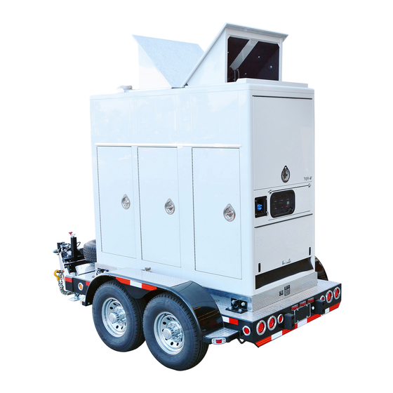
- Page 1 OPERATION MANUAL ® MODELS SG1400C4F SG1600C4F STUDIO GENERATOR (CUMMINS QSB7-G9 DIESEL ENGINE) Revision #0 (07/22/20) To find the latest revision of this publication or associated parts manual, visit our website at: www.mqpower.com THIS MANUAL MUST ACCOMPANY THE EQUIPMENT AT ALL TIMES.
-
Page 2: Proposition 65 Warning
PROPOSITION 65 WARNING PAGE 2 — SG1400/1600C4F STUDIO GENERATOR • OPERATION MANUAL — REV. #0 (07/22/20) -
Page 3: Reporting Safety Defects
If you believe that your vehicle has a defect that could cause a crash or could cause injury or death, you should immediately inform the National Highway Traffi c Safety Administration (NHTSA) in addition to notifying Multiquip Inc. at 1-800-421-1244. -
Page 4: Table Of Contents
TABLE OF CONTENTS SG1400C4F/SG1600C4F Generator Wiring Diagram Locator ......55 Generator Wiring Diagram EE58748 ....56-57 Studio Generator Generator Wiring Diagram EE58973 ....58-59 Proposition 65 Warning ........... 2 Generator Wiring Diagram EE58974 ....60-61 Reporting Safety Defects ......... 3 Generator Wiring Diagram EE59036 .... -
Page 5: Safety Information
SAFETY INFORMATION Do not operate or service the equipment before reading the Potential hazards associated with the operation of this entire manual. Safety precautions should be followed at all equipment will be referenced with hazard symbols which times when operating this equipment. Failure to read and may appear throughout this manual in conjunction with understand the safety messages and operating instructions safety messages. - Page 6 SAFETY INFORMATION GENERAL SAFETY „ NEVER use accessories or attachments that are not recommended by MQ Power for this equipment. Damage CAUTION to the equipment and/or injury to user may result. „ NEVER operate this equipment without proper protective „ ALWAYS know the location of the nearest clothing, shatterproof glasses, respiratory protection, fi re extinguisher.
- Page 7 SAFETY INFORMATION ENGINE SAFETY CAUTION „ NEVER touch the hot exhaust manifold, DANGER muffl er or cylinder. Allow these parts to cool „ The engine fuel exhaust gases contain poisonous carbon before servicing equipment. monoxide. This gas is colorless and odorless, and can NOTICE cause death if inhaled.
- Page 8 SAFETY INFORMATION FUEL SAFETY „ Make sure the hitch and coupling of the towing vehicle are rated equal to, or greater than the trailer “gross DANGER vehicle weight rating.” „ DO NOT start the engine near spilled fuel or combustible „...
- Page 9 SAFETY INFORMATION ELECTRICAL SAFETY „ Make sure power cables are securely connected to the generator’s output receptacles. Incorrect connections DANGER may cause electrical shock and damage to the generator. „ DO NOT touch output terminals during NOTICE operation. Contact with output terminals „...
- Page 10 SAFETY INFORMATION EMISSIONS INFORMATION „ If the battery liquid (dilute sulfuric acid) comes into contact with clothing or skin, rinse skin or clothing NOTICE immediately with plenty of water. The diesel engine used in this equipment has been „ If the battery liquid (dilute sulfuric acid) comes into designed to reduce harmful levels of carbon monoxide contact with eyes, rinse eyes immediately with plenty (CO), hydrocarbons (HC) and nitrogen oxides (NOx)
-
Page 11: Specifications
SPECIFICATIONS Table 1. Generator Specifications Model SG1400C4F/SG1600C4F Revolving field, self ventilated, Type open protected type synchronous generator Armature Connection 12-Lead WYE No of Poles Prime Output 282 hp (210 kWm) Voltage 120/240 V 1Ø Voltages 120/208 V and 277/480 V 3Ø... -
Page 12: Dimensions
DIMENSIONS TOP VIEW FRONT VIEW SIDE VIEW Figure 1. Dimensions Table 4. Dimensions Reference Dimensions Reference Dimensions Letter in. (mm) Letter in. (mm) 92 (2,336.8) 22.5 (571) 23 (584) NOTICE 119.6 (3,038.6) Chrome Wheels Trailer mounted generators have a fuel tank located inside 24 (610) 100 (2,514.6) the trailer frame. - Page 13 NOTES SG1400/1600C4F STUDIO GENERATOR • OPERATION MANUAL — REV. #0 (07/22/20) — PAGE 13...
-
Page 14: Installation
INSTALLATION CONNECTING THE GROUND Either copper or aluminum wire can be used as the ground cable. Cable size is determined by the maximum amperage Consult with local Electrical and Safety Codes for proper of the generator. Reference Conductor Grounding Table, connection based on condition of use. - Page 15 INSTALLATION GENERATOR GROUNDING OUTDOOR INSTALLATION NOTICE Install the generator in an area that is free of debris, bystanders, and overhead obstructions. Make sure the The Occupational Safety and Health Administration generator is on secure, level ground so that it cannot slide (OSHA) and the National Electrical Code (NEC) or shift around.
-
Page 16: General Information
The regulator provides voltage to the exciter resulting in for entertainment and studio applications. a build-up of generator terminal voltage. This system of In keeping with Multiquip's policy of constantly improving using residual magnetism eliminates the need for a special its products, the specifications quoted herein are subject field flashing circuit in the regulator. - Page 17 GENERAL INFORMATION Fuel Tank Trailer (Optional) This generator can be equipped with a 150 gallon (567 If equipped, the generator set can be mounted on a tandem liters) fuel tank located beneath the trailer deck. The tank axle trailer. Standard trailer is available with 8-lug chrome is made of steel (baffled).
-
Page 18: Generator Major Components
GENERATOR MAJOR COMPONENTS Table 5. Generator Major Components ITEM NO. DESCRIPTION SCR (Selective Catalytic Reduction) DPF (Diesel Particulate Filter) Hydraulic Cylinders Saddlebox Generator DEF Tank Hydraulic Oil Tank Hydraulic Filter Charge Air Cooler Heat Exchanger Fuel Out Hydraulic Drain Water Drain Oil Drain Fuel In Radiator... - Page 19 GENERATOR MAJOR COMPONENTS Figure 3. Major Components Table 6. Generator Major Components ITEM NO. DESCRIPTION Rain Cap Roof Intake/Exhaust Radiator Service Cap DEF Tank Filler Port Control Panel Camlok/Voltage Output Panel Manual Holder SG1400/1600C4F STUDIO GENERATOR • OPERATION MANUAL — REV. #0 (07/22/20) — PAGE 19...
-
Page 20: Generator Options
GENERATOR OPTIONS Table 8. Figure 4. Generator Options Table 7. Generator Options ITEM NO. DESCRIPTION Exterior LED Lights Block Heater Battery Charger Fire Extinguisher Transformer PAGE 20 — SG1400/1600C4F STUDIO GENERATOR • OPERATION MANUAL — REV. #0 (07/22/20) -
Page 21: Basic Engine Components
BASIC ENGINE COMPONENTS Figure 5. Basic Engine Components Table 9. Basic Engine Components ITEM NO. DESCRIPTION Alternator Oil Filter Starter-Solenoid Turbocharger Oil Filler Port Fuel Filter Oil Dipstick V-Belt Water Pump Oil Filler Port SG1400/1600C4F STUDIO GENERATOR • OPERATION MANUAL — REV. #0 (07/22/20) — PAGE 21... -
Page 22: Basic Trailer Components
BASIC TRAILER COMPONENTS Figure 6. Basic Trailer Components 9. Bumper Guard — Protects trailer frame when coming The definitions below describe the controls and functions in contact with stationary objects. of the Trailer (Figure 6). 10. License Plate Lights — Illuminates license plate. 1. -
Page 23: Control Panel
CONTROL PANEL Figure 7. Control Panel 9. Controller Power Switch — Provides power to engine The definitions below describe the controls and functions controller. of the Control Panel (Figure 7). 10. Voltage Status LEDs — During operation these status 1. Voltage Adjust Switch — To increase the output LED's will indicate the phase/voltage of the generator, voltage, pull upward and hold the switch until the 277/480, 3... -
Page 24: Camlok/Voltage Output Panel
CAMLOK/VOLTAGE OUTPUT PANEL FLAT WATERFALL GENERATOR TEST POINTS GENERATOR TEST POINTS L1 L2 CAUTION L1 L2 DO NOT CONNECT OR DISCONNECT CABLES WHEN BUS HOT LIGHT IS ILLUMINATED PARALLELING PARALLELING CB4 CB5 CB6 CB7 CABLE IN CABLE OUT BUS HOT 120 VAC 15 AMP 120 VAC... - Page 25 CAMLOK/VOLTAGE OUTPUT PANEL 7. Bates 120VAC Output Receptacles — These NOTICE receptacles provide AC voltage output. Each receptacle The Camlok/Voltage Output Panel is available in many is protected by a 100 amp breaker. These receptacles configurations. Figure 8 represents the most commonly cannot be used when the voltage selector switch is in used panels.
-
Page 26: Circuit Breaker Panel
CIRCUIT BREAKER PANEL Test Electronic Trip Unit Instantaneous Trip Setting - Amps A — 500 E — 1250 Push to Trip B — 600 F — 1500 450 AMP C — 800 G — 2000 LONG — INST. D — 1000 H —... -
Page 27: Digital Controller
DIGITAL CONTROLLER Figure 10. Digital Controller CONTROL BUTTONS Refer to Figure 10 for location of controls and indicators. 1. STATUS LED — Indicates status of the controller. 11. START Button — Press button to go idle mode (about Lights green when the controller is running. an hour) then generator starts. -
Page 28: Load Application/Generator Output
LOAD APPLICATION/GENERATOR OUTPUT SINGLE PHASE LOAD THREE PHASE LOAD Always be sure to check the nameplate on the generator When calculating the power requirements for 3-phase and equipment to insure the wattage, amperage, frequency, power use the following equation. and voltage requirements are satisfactorily supplied by the generator for operating the equipment. -
Page 29: Generator Outputs
GENERATOR OUTPUTS GENERATOR OUTPUT VOLTAGES CAUTION A wide range of voltages are available to supply voltage for NEVER change the position of the voltage selector many different applications. Voltages are selected by using switch while the engine is running. ALWAYS place the voltage selector switch (Figure 11). -
Page 30: Inspection/Setup
INSPECTION/SETUP MAIN CIRCUIT BREAKER FUEL CHECK DANGER The generator is equipped with a 3-pole, 600-amp circuit breaker to protect the camlok receptacles from overload. Fuel spillage on a hot engine can cause a Make sure that the main circuit breaker is in the OFF fire or explosion. - Page 31 INSPECTION/SETUP 1. Place the generator level with the ground. Failure to do 3. Monitor the fuel gauge while filling fuel tank. Stop filling when the fuel gauge indicates full (Figure 15). DO NOT so will cause fuel to spill from the tank before reaching full capacity (Figure 13).
- Page 32 INSPECTION/SETUP Refilling the Fuel System (Skid Mounted Generators) DEF Refueling Diesel exhaust fluid is an aqueous solution made with 32.5% NOTICE high puirty urea (carbamide) and 67.5 deionized water. If your generator is skid mounted, an external fuel sytem DEF is used as a consumable in selective catalytic reduction will be required.
- Page 33 INSPECTION/SETUP COOLANT (ANTIFREEZE/SUMMER COOLANT) CLEANING THE RADIATOR Cummins recommends antifreeze/summer coolant, for use The engine may overheat if the radiator fins become in their engines, which can be purchased in concentrate (and overloaded with dust or debris. Periodically clean the mixed with 50% demineralized water) or pre-diluted.
- Page 34 INSPECTION/SETUP BATTERY When connecting the battery do the following: 1. Place a small amount of battery terminal treatment This unit is of negative ground. DO NOT connect in reverse. compound around both battery terminals. This will Always maintain battery fluid level between the specified ensure a good connection and will help prevent marks.
-
Page 35: Startup
STARTUP BEFORE STARTING NOTICE CAUTION If it is necessary to prime engine before starting (such as after changing a fuel filter or running out of fuel), The engine’s exhaust contains harmful emissions. please reference the maintenance section in this ALWAYS have adequate ventilation when operating. manual "Priming The Engine". - Page 36 STARTUP 7. Press the GCB control button on the controller (Figure 27) to close circuit breaker. Close GCB PRESS MODE BUTTON PRESS GCB CONTROL BUTTON Figure 25. Mode Button (Manual) Figure 27. Generator Circuit Breaker (Closed) STARTING (MANUAL) 8. Verify that the BUS HOT light (Figure 28) on the 1.
- Page 37 STARTUP CLOSING THE ENCLOSURE DOORS 1. Close the enclosure doors once the generator has started (Figure 29). Top vents stay open for proper ventilation. PRESS BUTTON Figure 30. Generator Circuit Breaker (Open) RAIN DOOR INTAKE VENT CLOSE DOORS STOP BUTTON Figure 29.
-
Page 38: Protective Devices
PROTECTIVE DEVICES PROTECTIVE DEVICES After automatic shutdown, always inspect the generator and eliminate any problems that might have caused the Protection devices and emergency stop devices are shutdown before attempting to restart the generator. designed as standard components for protection of the When ready to restart, check and make sure that no generator against trouble during operation. -
Page 39: Maintenance
MAINTENANCE Use Table 18 as a general maintenance guideline when servicing your engine. For more detail engine maintenance information, refer to the engine owner’s manual supplied with your engine. Table 18. Engine Maintenance Schedule INTERVAL 250 HOURS 500 HOURS 1000 HOURS 2000 HOURS 5000 HOURS DESCRIPTION... - Page 40 MAINTENANCE GENERAL INSPECTION 2. Remove the air filter cover and set aside. 3. Remove both the primary and secondary air filter Prior to each use, the generator should be cleaned and elements (Figure 34) from the case/body. inspected for deficiencies. Check for loose, missing or damaged nuts, bolts, and other fasteners.
- Page 41 MAINTENANCE NOTICE AIR FILTER CASE DO NOT use excessive air pressure or the paper air filter element will be damaged and will need to be replaced. If air filters are excessively dirty (oily). Replace air filters, DO NOT clean. CAUTION Wear protective gear such as approved safety glasses or face shields and dust masks or respirators when cleaning air...
- Page 42 MAINTENANCE Air Filter Dust Indicator REPLACING FUEL FILTER NOTICE Replace the fuel filter cartridge with a new one every 500 hours. The air filter should not be changed until the indicator reads “RED”. Dispose of the old air filter. It may not be 1.
- Page 43 MAINTENANCE CLEANING FUEL STRAINER FUEL Inspect fuel strainer daily. Clean if necessary. STRAINER 1. Using a wrench, turn the nut at the bottom of the fuel strainer counterclockwise to remove the bowl from the fuel strainer head. FILTER HEAD SCREEN O-RING Figure 41.
- Page 44 MAINTENANCE DRAINING FUEL WATER SEPARATOR REPLACING FUEL WATER SEPARATOR Inspect fuel water separator daily. Clean if necessary. 1. Replacement of the fuel water separator is easy, simply turn the cartridge counterclockwise and remove from 1. Over a period of time sediment and foreign matter head assembly.
- Page 45 MAINTENANCE AIR REMOVAL, BLEED THE SYSTEM 3. Next, PUSH the air bleed knob (Figure 46) in and out until the fuel system has been completely purged NOTICE (removal of air) the knob is spring loaded. If air enters the fuel injection system of a diesel engine, starting becomes impossible.
- Page 46 MAINTENANCE FUEL ADDITION CHECK OIL LEVEL Check engine oil level daily. Add diesel fuel (the grade may vary according to season and locations). Only use Ultra Low Sulfur diesel fuel when Check the crankcase oil level prior to each use, or when refilling fuel tank.
- Page 47 MAINTENANCE ENGINE OIL FILTER REPLACEMENT Table 19. Oil Selection Chart Replace engine oil filter every 250 hours. OIL: SAE 1. Using an oil filter wrench (Figure 51A), remove engine oil filter. 2. Clean the area around the lubricating oil filter head. OIL FILTER HEAD OIL FILTER...
- Page 48 MAINTENANCE DRAINING HYDAULIC OIL 1. To drain the hydraulic fluid, remove the hydraulic fluid drain plug located at the base of the skid as shown in Figure 52 and allow the fluid to drain into a suitable container. HYDRAULIC OIL FILTER HYDRAULIC OIL HEAD FILTER...
- Page 49 MAINTENANCE 3. After engine coolant has been completely drained, WARNING reinstall drain plug and tighten securely. DO NOT remove the pressure cap from the radiator FLUSHING RADIATOR when the engine is hot! Wait until the coolant temperature is below 120°F (50°C) before removing WARNING pressure cap.
- Page 50 MAINTENANCE RADIATOR CLEANING DEF TANK SUPPLY MODULE FILTER The radiator (Figure 56) should be sprayed (cleaned) with Replace DEF Supply Module Filter every 4500 hours. a high pressure washer when excessive amounts of dirt 1. Remove cap (Figure 57) at the bottom of DEF supply and debris have accumulated on the cooling fins or tube.
- Page 51 MAINTENANCE EMISSION CONTROL The Diesel Particulate Filter (DPF) is a device designed to remove diesel particulate matter or soot from the exhaust The emission control system employed with the diesel gas of a diesel engine. These exhaust emissions pose engine consists of a Diesel Particulate Filter (DPF) and serious environmental and health risks.
-
Page 52: Troubleshooting (Generator)
TROUBLESHOOTING (GENERATOR) Troubleshooting (Generator) Symptom Possible Problem Solution AC Voltmeter defective? Check output voltage using a voltmeter. Is wiring connection loose? Check wiring and repair. No Voltage Output Is voltage regulator defective? Replace if necessary. Defective Rotating Rectifier? Check and replace. Defective Exciter Field? Check and replace. -
Page 53: Troubleshooting (Engine)
TROUBLESHOOTING (ENGINE) Troubleshooting (Engine) Symptom Possible Problem Solution No Fuel reaching injection pump? Add fuel. Check entire fuel system. Defective fuel pump? Replace fuel pump. Fuel filter clogged? Replace fuel filter and clean tank. Faulty fuel supply line? Replace or repair fuel line. Check piston, cylinder and valves. -
Page 54: Troubleshooting (Controller)
TROUBLESHOOTING (CONTROLLER) Troubleshooting (Intelivision 5 Controller) Symptom Possible Problem Solution Wrong Display HW SW and HW mismatch? Correct firmware has to be programmed. Invalidate configuration table Controller configuration has to be reprogrammed or Configuration table is invalid? Error upgraded. Unsupported controller Error Controller is not supported? Controller upgrade necessary. -
Page 55: Generator Wiring Diagram Locator
GENERATOR WIRING DIAGRAM LOCATOR EE56444 EE56762 EE56518 NOTICE Letters inside the GREEN balloons can be referenced on the associated "Generator Wiring Diagrams". SG1400/1600C4F STUDIO GENERATOR • OPERATION MANUAL — REV. #0 (07/22/20) — PAGE 55... -
Page 56: Generator Wiring Diagram Ee58748
GENERATOR WIRING DIAGRAM EE58748 GRY/RED DEF SHR GRY/RED GRYRED DC31 BLU/WHT BLU/YEL DEF SUPPLY MODULE STARTER SOLENOID DEFSUPPLY HEATER RELAY HEATER RELAY WORK LIGHT TIMER DEF LHRP WATER IN FUEL CONTROL POWER CB11 CB12 BLU/RED YELLOW DEF LINE HEATER BLU/RED DC32 GRN/RED BRN/YEL... - Page 57 GENERATOR WIRING DIAGRAM EE58748 BLK/GRY BLK/PNK WHT/PNK NOTICE MODULE PUR/GRY BRN/GRY EATER ORG/PNK YEL/PNK SURE) Letters inside the GREEN balloons can be GREEN EATER FIELD KFLOW) referenced on the "Generator Wiring Diagram GROUND STUD EATER BASLER BE2000E TION) Locator". Battery Charger and Block Heater MODULE BLU/GRY DC27...
-
Page 58: Generator Wiring Diagram Ee58973
GENERATOR WIRING DIAGRAM EE58973 15 AMP 15 AMP 15 AMP 15 AMP 120/240 PAGE 58 — SG1400/1600C4F STUDIO GENERATOR • OPERATION MANUAL — REV. #0 (07/22/20) - Page 59 GENERATOR WIRING DIAGRAM EE58973 120V 50 AMP 120/240 VAC 1Ø 50 AMP 50 AMP 120/240 VAC 1Ø 50 AMP AC10 AC11 AC12 NOTICE Letters inside the GREEN balloons can be referenced on the "Generator Wiring Diagram Locator". AC20 AC21 AC22 100 AMP 100 AMP 100 AMP...
-
Page 60: Generator Wiring Diagram Ee58974
GENERATOR WIRING DIAGRAM EE58974 15 AMP 15 AMP 15 AMP 15 AMP 120/240 PAGE 60 — SG1400/1600C4F STUDIO GENERATOR • OPERATION MANUAL — REV. #0 (07/22/20) - Page 61 GENERATOR WIRING DIAGRAM EE58974 50 AMP 120V 120/240 VAC 1Ø 50 AMP 100 AMP 100 AMP 50 AMP 120/240 VAC 1Ø 50 AMP NOTICE Letters inside the GREEN balloons can be referenced on the "Generator Wiring Diagram Locator". Battery Charger and Block Heater AC10 AC11 locations are shown below.
-
Page 62: Generator Wiring Diagram Ee59036
GENERATOR WIRING DIAGRAM EE59036 15 AMP 15 AMP 15 AMP 15 AMP 120/240 PAGE 62 — SG1400/1600C4F STUDIO GENERATOR • OPERATION MANUAL — REV. #0 (07/22/20) - Page 63 GENERATOR WIRING DIAGRAM EE59036 50 AMP 120/240 VAC 1Ø 50 AMP 120V 100 AMP 50 AMP 100 AMP 120/240 VAC 1Ø 50 AMP NOTICE Letters inside the GREEN balloons can be referenced on the "Generator Wiring Diagram Locator". Battery Charger and Block Heater locations are shown below.
-
Page 64: Generator Wiring Diagram Ee59183
GENERATOR WIRING DIAGRAM EE59183 15 AMP 15 AMP 15 AMP 15 AMP 120/240 1Ø 120/240 PAGE 64 — SG1400/1600C4F STUDIO GENERATOR • OPERATION MANUAL — REV. #0 (07/22/20) - Page 65 GENERATOR WIRING DIAGRAM EE59183 50 AMP 120V 120/240 VAC 1Ø 50 AMP 100 AMP 100 AMP 50 AMP 120/240 VAC 1Ø 50 AMP AC10 NOTICE AC11 AC12 Letters inside the GREEN balloons can be AC14 AC15 referenced on the "Generator Wiring Diagram Locator".
-
Page 66: Generator Wiring Diagram Ee60365
GENERATOR WIRING DIAGRAM EE60365 15 AMP 15 AMP 15 AMP 15 AMP 120/240 PAGE 66 — SG1400/1600C4F STUDIO GENERATOR • OPERATION MANUAL — REV. #0 (07/22/20) - Page 67 GENERATOR WIRING DIAGRAM EE60365 50 AMP 120/240 VAC 1Ø 50 AMP 120V 100 AMP 50 AMP 100 AMP 120/240 VAC 1Ø 50 AMP AC10 AC11 AC12 NOTICE AC14 AC15 Letters inside the GREEN balloons can be referenced on the "Generator Wiring Diagram Locator".
-
Page 68: Hydraulic Diagram Locator
HYDRAULIC DIAGRAM LOCATOR PAGE 68 — SG1400/1600C4F STUDIO GENERATOR • OPERATION MANUAL — REV. #0 (07/22/20) - Page 69 HYDRAULIC DIAGRAM LOCATOR SG1400/1600C4F STUDIO GENERATOR • OPERATION MANUAL — REV. #0 (07/22/20) — PAGE 69...
-
Page 70: Hydraulic Diagram
MHYDRAULIC DIAGRAM EXHAUST CYLINDERS 1/4” NPT DIRECTIONAL CONTROL VALVE DIRECTIONAL CONTROL VALVE PAGE 70 — SG1400/1600C4F STUDIO GENERATOR • OPERATION MANUAL — REV. #0 (07/22/20) - Page 71 NOTES SG1400/1600C4F STUDIO GENERATOR • OPERATION MANUAL — REV. #0 (07/22/20) — PAGE 71...
- Page 72 © COPYRIGHT 2020, MULTIQUIP INC. Multiquip Inc , the MQ logo are registered trademarks of Multiquip Inc. and may not be used, reproduced, or altered without written permission. All other trademarks are the property of their respective owners and used with permission.
Need help?
Do you have a question about the MQ POWER SG1400C4F and is the answer not in the manual?
Questions and answers