Table of Contents
Advertisement
Quick Links
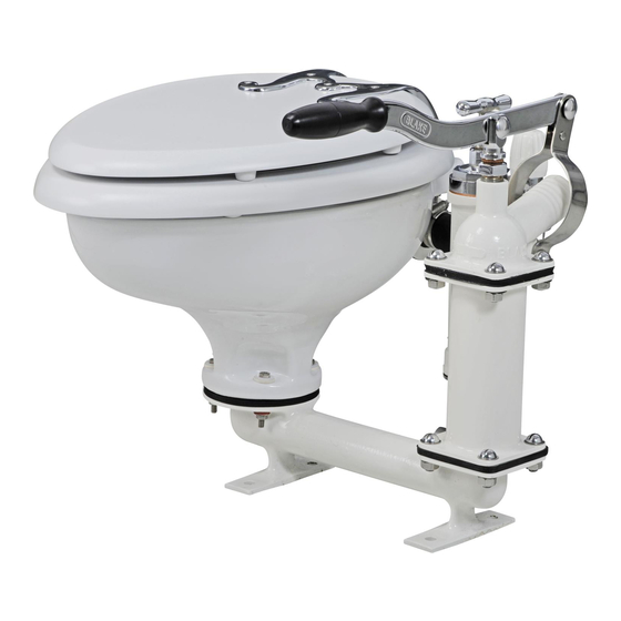
LAVAC Marine Toilets
Manual
Contents
Introduction/Installation kit
Lavac System
Zenith Exploded Diagram
Parts list, Accessories & specification
Popular Exploded Diagram
Parts list, Accessories & specification
Manual Pump Exploded diagram
Parts list, Accessories & specification
Electric Pump Exploded diagram
Parts list, Accessories & specification
Zenith and Popular Spares kits
Lavac Operation diagrams
Installation
Seacocks
Lavac toilets
Electric pump
General
Lavac
Plumbing
Operating your marine toilet
Lavac Maintenance
Replacing perishable parts
Operational solutions
TOPLICHT 20.August 2019
Notkestraße 97 · 22607 Hamburg
2
3
4
5
6
7
8
9
10
11
12
13
14
15
17
18
19
20
22
23
24
25
27
Schiffsausrüster
Tel.: +49 ( 0 ) 40 - 88 90 100
www.toplicht.de
Advertisement
Table of Contents

Related Manuals for Toplicht BLAKES LAVAC Zenith

Summary of Contents for Toplicht BLAKES LAVAC Zenith
- Page 1 Lavac Operation diagrams Installation Seacocks Lavac toilets Electric pump Holding Tanks General Lavac Plumbing Accessories Operating your marine toilet Lavac Maintenance Replacing perishable parts Operational solutions Schiffsausrüster TOPLICHT 20.August 2019 Tel.: +49 ( 0 ) 40 - 88 90 100 www.toplicht.de...
- Page 2 The Lavac Installation kit provided with your lavac Congratulations on the purchase of a Lavac marine toilet. Lavac marine toilets are firm All Lavac marine toilets are provided wit the favourites with sailors throughout the world, following parts for installation. providing their owner with a long and trou- ble free working life.
- Page 3 The Lavac System General Features The well known Lavac system is unique Easy and versatile in installation. and probably the only single action, above Can be mounted under bunk or locker or below water line, marine WC. and pulled out for use. Pump, separate from bowl, can be The Lavac has a china pan and is available mounted in most convenient position...
- Page 4 Exploded diagram of the Lavac Zenith PRODUCT UPDATE New Thermo-set seal (11) introduced July 1993 with no joins or weld points. Cross-section below showing longer sealing lip conforms bet- ter to contact surface (seat or bowl) for improved vacuum. PRODUCT UPDATE New white rubber washer for dome nut.
- Page 5 Lavac Zenith Zenith Components Diagram No Part No Description TBB7215 x 4 M6 Nuts TLZ9021 x 4 Pan bolt washers - small TLZ9022 x 4 Pan bolt washers - large TLZ9022 x 4 M6 x 35 Pan bolt TLZ9005 Pedestral base TLZ9010 Pan base joint 6, 7, 8, 9...
- Page 6 Exploded diagram of the Lavac Popular...
- Page 7 Lavac Popular Popular Components Diagram No Part No Description TLZ9005 Pedestal base TLZ9010 Pan base joint TLZ8015 x 4 M6 x 50 Pan bolt TLZ8010 x 4 Plastic covers TLZ8022 x 4 Plastic washer TLZ8021 x 4 Stainless steel washer TLZ8020 x 4 M6 nuts TLZ8025...
- Page 8 Exploded diagram of Hand Pump U/D Pump Handle Position T/A Pump Handle Position Note: Bulkhead plate and shroud for the U/D pump (makes a neat, flush installation – Spares No: TLZ9460, see installation diagram on p.15).
- Page 9 Lavac Zenith & Popular Hand Pump Components Diagram No Part No Description TLZ9110 Diaphragm TLZ9175 x 8 2BA x 1” Bolts TLZ9181 x 8 2BA nuts TLZ9330 Inlet valve - hand TLZ9335 Inlet valve plate TLZ9320 Front cover TLZ9325 Front cover seal TLZ9125 Eye bolt nut TLZ9100...
- Page 10 Exploded diagram of the electric pump – 12&24 Volt...
- Page 11 Lavac Zenith & Popular Electric Pump Components Diagram No Part No Description TLZ9110 Diaphragm TLZ9175 x 8 2BA x 1” Bolts TLZ9181 x 8 2BA nuts TLZ9330 Inlet valve - hand TLZ9335 Inlet valve plate TLZ9320 Front cover TLZ9325 Front cover seal TLZ9125 Eye bolt nut TLZ9100...
- Page 12 Lavac Zenith Zenith spares kits Description Part No Hand pump kit 12 or 24V electric pump kit TLZ0954 TLZ0952 Hand pump spares kit TLZ0951 Electric pump spares kit TLZ0956 Pan base gasket (5) TLZ9010 Sealing washer for inlet spigot (7) TLZ9035 Rubber washer (17a) TLZ9054...
- Page 13 Lavac operation...
- Page 14 Installation – seacocks Siting and installing the seacocks GRP hulls, a small amount of under- Having chosen the type of inlet and water sealing compound should be discharge seacocks required for put between the inside skin and this your particular needs, they should pad and also under the seacock be mounted in the hull.
- Page 15 Lavac Installation Summary Typical installation 1. INLET SEACOCK Should be mounted forward of the discharge to avoid recirculating waste. We recommend the use of Blakes seacocks. 2. PUMP (Hand or Electric) Diagram on the right shows a U/D hand pump installation with U/D pump plate and shroud.
- Page 16 Lavac Installation Handle position (angle of operation) and/or outlet direction can be varied by rotating pump body (26) relative to back cover (35) (See exploded inlet and, particularly, the outlet diagram p.8). hoses. If it is completely unavoid- If back cover (35) is rotated ensure air bleed hole able to use right angled fittings in in back cover is re-drilled at lowest point.
- Page 17 Lavac Electric pump Installation Connect up wiring as indicated in the diagram. The time switch should be mounted through the bulkhead so that only the front flange with push button and shroud are visible to the user. Use only stainless steel screws. The time switch is set for 30-45 sec- onds.
- Page 18 Holding Tanks – General Options Materials Recirculating pump out – often used If a holding tank system is being for a conversion installation where considered, some careful thought the toilet compartment is sufficiently must be given to the design and roomy.
- Page 19 Holding Tanks – Lavac Economy of Flushing Water Ideal for Recirculating System Economy of flushing water is a valu- Although the Lavac has ideal features able Lavac characteristic for holding for fresh water flushing systems, in tank installations. This is also impor- extreme circumstances it may be pre- tant when flushing water is being ferred to minimise the holding tank...
- Page 20 Holding Tank Plumbing Key Points Ball Check Valve for ¾“ bore hose For all systems where pump-out (only required if draw is more than via deck fitting, or via seacock, 36“ below toilet) or vented loop is not required either can be required if toilet is below waterline.
- Page 21 2 - For craft visiting waters where Pump-out deck fitting overboard discharge is prohibited. This system is simple to oper- Vented ate. Use of quay side marina Loop Lavac Pump. pump out station is not restrict- Hand and/ or Electric ed by the on board, in line, pump.
- Page 22 4 - An alternative to fig.3. This sys- tem provides a self pump-out facility to Pump-out deck fitting shore or sea, suing the one toilet A/B/D ‘T’ or ‘Y’ connection pump. Only installations with Lavac Vented B/C/D A/B/D Loop toilets can operate this system. When ‘T’...
- Page 23 Operation Electric pump operation Manual pump operation 1. To flush the toilet, close the seat 1. To flush the toilet, close the and lid and press the push but- seat and lid and give 8-10 ton fully in and release it. steady pulls using the full movement of the handle.
- Page 24 Maintenance Toilet cleaners Day to day points to remember Seat and lid 1. Ensure that the operating Only use soapy water. Difficult instructions are mounted stains can be removed with alco- hol, e.g. methylated spirits. where your guests will see them.
- Page 25 Maintenance – Perishable parts Replacing the seat and lid seals 1. Hook one end of the seal under the rim of the lid, stretch the seal around the rim and clip under all way round. Photo 1. 2. Repeat for the seat. Photo 1 Replacing the perishable pump parts...
- Page 26 Maintenance – Perishable parts 3. Unscrew the eyebolt (25) nut 5. Unscrew 2 short and 2 long and remove diaphragm (20 screws (28) to remove the out- complete with diaphragm let valve (27) Replace. plates (29) Replace diaphragm (20). photo 4 Photo 6 4.
- Page 27 Operational Solutions Fault Possible cause Solution No flushing water Inlet seacock closed. Open inlet seacock and check that the drawn in when outlet seacock is open as well. bowl emptied. Failure of vaccum When the seat and lid are closed and the pump operated, the bowl should be sealed for around 30 seconds, i.e.
- Page 28 Operational Solutions Fault Possible cause Solution Pump handle Pump blockage Check through the front cover for blockage easy to operate holding the inlet valve open. but bowl will not discharge Scale build up in This scale, which builds up over a variable pump.
- Page 29 Operational Solutions Fault Possible cause Solution Electric pump Pump not running The pump should run for a minimum of 1 does not flus sys- long enough. minute and possibly longer in installations tem properly where the pipe runs are unusually long. Running time can be increased/ decreased by fractional turns of the small screw locat- ed in the centre rear of the time switch.
- Page 30 Operational Solutions Blockages in the pump If a blockage occurs in the pump, first pour half a bucket of water in the bowl and then, with the lid open, pump with even firm strokes until the water leaves the bowl. This should clear the pump but repeat if necessary and then close the lid and pump again to replace the correct amount of water in the bowl.
- Page 31 Note...
Need help?
Do you have a question about the BLAKES LAVAC Zenith and is the answer not in the manual?
Questions and answers