Table of Contents
Advertisement
Quick Links
Advertisement
Table of Contents

Summary of Contents for Power Tower Nano SP Plus
- Page 1 Operating and Maintenance Manual Courtesy of Crane.Market...
-
Page 2: Table Of Contents
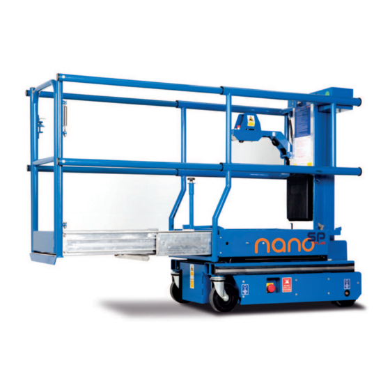
CONTENTS CONTENTS INTRODUCTION The Power Tower Nano SP Plus is designed to be a simple, safe and Operating Specifications efficient self-propelled alternative to push-around platforms or traditional scaffold tower or podium steps. It can be used for many Working Envelope Diagram applications including construction and maintenance where the convenience and efficiency of using a self-propelled platform is... -
Page 3: Operating Specifications
OPERATING SPECIFICATIONS Working Dimensions Maximum working height: 4.50m Maximum platform height: 2.50m Outreach with cantilever deck to cage edge: 1.00m Basket dimensions - cantilever closed: 1.00m x 0.73m Basket dimensions - cantilever extended: 2.00m X 0.7m Working footprint: 1.19m x 0.75m Safe working load: 200kg (1 person plus tools) Maximum manual force:... -
Page 4: Do's And Don'ts
20dN). Ensure operator is fit and does not suffer from fear of heights. Never drive Nano SP Plus near holes in the floor (or edge of concrete slab, manholes, drains etc.) Ensure guardrail gate is closed and latched before elevation. -
Page 5: Primary Components
PRIMARY COMPONENTS PRIMARY COMPONENT LOCATIONS Tool Tray Entrance Control Arm Gate Latch (Folded) Basket Retaining Amber Latch Flashing Beacon Emergency Stop/Battery Isolator Drive Wheel Manual Emergency Ground Control Swivel Spirit Safety Prop (Motor Gearbox) Lowering Valve Station Castor Level Courtesy of Crane.Market... -
Page 6: Operating Procedures (Incl. Emergency Operation)
Basket SP Plus product. Gas Struts Main Control Cable (Curly) The Nano SP Plus is fitted with a lanyard attachment point as standard. It is recommended that if the operator chooses to wear a safety harness, an approved ‘fall restraint’... -
Page 7: Pre-Operation Checks
The ground must bare the before normal use: total weight of the Nano SP Plus plus payload (i.e. 550kg + 200kg): a 1. Check lift functions at ground and in basket by lifting hard level surface is required e.g. - Page 8 PLATFORM OPERATION PLATFORM OPERATION This machine is fitted with a double extension cantilever platform, When extending or retracting the platform, do not stand on the which combines very compact closed dimensions with a large moving floor elements. Additionally, do not extend or retract the extended platform work area.
- Page 9 Extend platform if required. as required. Drive speed is infinitely variable depending on how far the joystick is moved. To stop the Nano SP Plus release the joystick. The ideal position to operate the Nano SP Plus is to stand facing towards the gate end with your back against the mast.
- Page 10 OPERATING PROCEDURES EMERGENCY OPERATION The Nano SP Plus is fitted with two modes of emergency lowering, From the ground: one from the basket and one at the ground. NB Always check the area In the event of control failure or operator incapacity the emergency below the platform is free from obstructions before lowering, and lowering valve located on the chassis (location;...
-
Page 11: Maintenance Procedures
BATTERY CHARGING The battery charger is located under the checkerplate cover First switch off Nano SP Plus and isolate power by depressing the battery isolator switch at base of machine. The charging lead (usually fitted with a yellow 110V plug) is on the exterior of the machine base (this lead can be fitted with 230V plug if required) - Page 12 MAINTENANCE PROCEDURES Please note that whilst the Nano SP Plus is extremely simple to To access the main component compartment you must first maintain, all work must be carried out by a competent person. tilt basket. Before doing this check that there is no damage...
- Page 13 MAINTENANCE PROCEDURES WEEKLY MAINTENANCE Check key fixings are secure: on wheels and castors, cage pivot fixing, Refill with grade 32 mineral oil. basket tray bolts, cantilever deck stops. WHEELS AND CASTORS Check battery terminal connections are tight. It is absolutely essential that the drive wheels and castors are maintained in good condition at all times, for two reasons: Check mast rollers and mast surfaces for damage or ingrained debris.
- Page 14 MAINTENANCE PROCEDURES approximately 12mm, but may vary slightly is approximately 25-30mm from the ground. MAST MAINTENANCE The mast sections run on maintenance free due to manufacturing tolerances. This should really be repeated from both sides of the machine to compensate for out rollers, and on the outer mast surface where the roller runs, a brush is fitted to keep the Loosen the wear screw lock nut and turn the...
- Page 15 MAINTENANCE PROCEDURES MAINTENANCE FREQUENCY MAINTENANCE FREQUENCY TABLE Item Daily Monthly 6 Months 12 Months Batteries/Connections Oil Level Visual Inspection Spirit Level Castors Check Mast & Rollers Change Hydraulic Oil Motor Gearbox Cantilever Deck Mechansim Load sensing Mechanism Thorough examination (LOLER) High/Low Speed Drive Tilt Switch Operation Thorough examination must include checking:...
-
Page 16: Storage
STORAGE OF Nano SP Plus STORAGE If the machine is to be taken out of operation for a period longer than one month, the following precautions should be taken. Depress the battery isolator (large red stop button) on side of chassis. -
Page 17: Key Spare Parts
KEY SPARE PARTS STORAGE OF Nano SP Plus ELECTRICAL PARTS Part No. Emergency Stop Button – platform PT-E-003 Emerg. Stop c/w Key Switch - ground PTNSP-E-614 Joystick Module PTNSP-E-601 Black Emergency Lower Button – platform PT-E-007 LED (Red) – Control Arm... - Page 18 KEY SPARE PARTS ELECTRICAL PARTS Part No. Emergency Stop/Battery Isolator- chassis PTNSP-E-621 PTNSP-E-602 Drive Motor/Gearbox complete - RHS PTNSP-E-616R Drive Motor/Gearbox complete – LHS PTNSP-E-616L Drive Motor Brake PTNSP-E-617 24/8 A Battery Charger PTNSP-E-630 12v 105A Traction Battery PT-E-002 HYDRAULIC PARTS 24v DC Powerpack Complete PTNSP-H-551 Powerpack Valve Cartridge...
- Page 19 KEY SPARE PARTS MECHANICAL AND MISCELLANEOUS PARTS Part No. Drive Wheel PTNSP-M-500 H.D. Swivel Castor PTNSP-M-501 Power-pack Cabinet Cover Plate PTNSP-M-521 ECU Cover Plate PTNSP-M-522 Guardrails Outer PTNSP2-M-801 Inner Guradrails c/w Gate PTNSP2-M-802 Gate PTNSP2-M-804 Platform Deck Tray PTNSP2-M-805 First Extension Deck Tray PTNSP2-M-806 Second Extension Deck Tray PTNSP2-M-807...
- Page 20 KEY SPARE PARTS MISCELLANEOUS PARTS Part No. Platform Tray Slide Channel (Pair) PTNSP2-M-809 Second Extension Tray Slide Channel (Pair) PTNSP2-M-810 Control Arm PTNSP-M-533 Gas Strut Platform (Large) PTNSP-M-520 Gas Strut Platform (Small) PTN-M-340 Gas Strut Control Arm PTNSP-M-519 Cantilever Tread-Lock PTNSP2-M-808 Basket safety prop c/w fixing PTNSP-M-529...
-
Page 21: Electrical Circuit Diagram
CIRCUIT DIAGRAM - ELECTRICAL Courtesy of Crane.Market... -
Page 22: Hydraulic Circuit Diagram
CIRCUIT DIAGRAM - HYDRAULIC Relief Valve preset to 65 Bar Single Action 2 stage lift cylinder NA-HP-003 Steel Pipe 12V/24V DC Powerpack Manual Bypass Solenoid Lock Valve Courtesy of Crane.Market... -
Page 23: Warranty Terms
If additional equipment or any third party work, modifications or installation, loading or operation instructions. alterations are to be carried out on the Nano SP Plus which will involve any welding, drilling or any form of cutting or distortion Alterations, additions or repairs carried out by persons other than the of materials, full written approval must be obtained from the Manufacturer or their recognised distributors. - Page 24 N-PLUS-OP | UK | 1.12 100% British designed www.powertowers.com and manufactured. Courtesy of Crane.Market...
Need help?
Do you have a question about the Nano SP Plus and is the answer not in the manual?
Questions and answers