Table of Contents
Advertisement
Quick Links
INST R U C T IO N M A NU A L
INST A LLA T IO N | W IR ING | C O M M ISSIO NING | M A INT ENA NC E |
I S O 9 0 0 1
ISO 14001
Q u a l i t é
Environnement
AFNOR CERTIFICATION
AFNOR CERTIFICATION
®
K SC R EC O W A T T
0 8 / 1 8 / 2 8 / 3 8 / 5 2
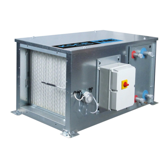
Compact controlled single flow air handling unit (AHU)
NT00000534-KSCR-ECOWATT-08-18-28-38-52-AN-200625
Advertisement
Table of Contents

Subscribe to Our Youtube Channel
Related Manuals for ViM KSCR ECOWATT 08


Summary of Contents for ViM KSCR ECOWATT 08
-
Page 1: C O M M Issio Ning
INST R U C T IO N M A NU A L INST A LLA T IO N | W IR ING | C O M M ISSIO NING | M A INT ENA NC E | I S O 9 0 0 1 ISO 14001 Q u a l i t é... -
Page 2: Table Of Contents
TABLE OF CONTENTS GENER A L INF O R M A T IO N ..................3 Warnings .......................... -
Page 3: Gener A L Inf O R M A T Io N
It must comply with the requirements relating to the Electromagnetic Compatibility (EMC) and the Low Voltage Directive. VIM will not be responsible for any possible bodily injury and/or material damage caused when the safety instructions have not been followed or following a modification of the product. -
Page 4: Safety Guidelines
W a r r a n t y The material provided by VIM is guaranteed for 12 months - Parts only - from the invoice date. VIM un- dertakes to replace any parts or equipment which are recognised by our services as being faulty, with the exception of any damages, interests, or penalties such as operating losses, commercial prejudice, or other immaterial or indirect damages. -
Page 5: P R Esent A T Io N O F R A Nge - P R O D U C T
- The ASR ECOWATT system for association with a KUBAIR F400 ECOWATT or a TED F400 ECOWATT - Consult the manual "NT00000438-SYSTEME-ASR-ECOWATT" available on www.vim.fr. - Temperature control by integrated CORRIGO controller specific to VIM. - Modbus communicating on RS485 port and Bacnet IP on TCP/IP port. -
Page 6: Functional Diagrams
2 . 2 F u n c t i o n a l d i a g r a m s For any specific configuration contact the VIM After sales service. Outdoor air Supply air Aspiration air neuf Sou age air neuf... -
Page 7: Products - Main Components
K SC R EC O W A T T ® w i t h w a t e r c o i l ( EC F ) Outdoor air Supply air Sou age air neuf Aspiration air neuf Bat1 Bat2 Pr10 Fresh air damper (accessory) Flow measurement... -
Page 8: Inst A Lla T Io N
INS T A LL A T I O N Unit identification / Symbols 3 . 1 Identification label - stuck on the machine above the control cabinet 3 . 2 D i m e n s i o n s a n d w e i g h t s ®... - Page 9 He a t i n g c o i l + c o o l i n g c o i l ( EC F ) C a s i n g d i m e n s i o n s ( m m ) A t t a c h m e n t ( m m ) Si z e ®...
- Page 10 He a t i n g c o i l ( EC ) , r e v e r s i b l e c o i l ( ER ) o r h e a t i n g a n d c o o l i n g c o i l s ( EC F ) Reversible Heating coil EC coil ER...
-
Page 11: Handling
3 . 3 Ha n d l i n g The units are delivered screwed to pallets made to fit the size of the casing. air handling units can be handled by pallet truck, forklift truck, or crane. Handling ma- ®... - Page 12 Su s p e n d e d m o u n t i n g F l o o r m o u n t L mini > L H mini > H H mini > H L mini > L 3 .
- Page 13 - Reverse the tray by fitting it onto the top of the coil - Reintroduce the assembly in the casing - Reverse the plug and the pipe bushing, and refit the drawer. 3 . 4 . 2 K SC R 5 2 s u p e n d e d c e i l i n g i n s t a l l a t i o n In v e r s i o n o f t h e d r a i n t r a y K SC R EC O W A T T ®...
-
Page 14: Filters And Components Access
3 . 5 F i l t e r s a n d c o m p o n e n t s a c c e s s K SC R 0 8 à 3 8 F i l t e r s a n d c o m p o n e n t s a c c e s s ... -
Page 15: Hy D R A U Lic A Nd F Lu Id C O Nnec T Io
F i l t e r ( s ) r e p l a c i n g b y t h e u p p e r p a n e l - Unscrew and remove the filter - Unlock the holding beam by - Remove the filter(s) for panel, with black quarter-turn hexagonal... - Page 16 The hydraulic specifications of the unit are particular to your requirement and are determined by computer selection: Loss of pressure of the wa- ter/water flow. Refer to the selection for sizing the valve, accessories, and pump. The connection of the piping to the coil must not impose any mechanical, vibration or thermal (dilation) constraints.
-
Page 17: Condensing Water Outlet (Versions Er, Ef, And Ecf Only)
4 . 2 C o n d e n s i n g w a t e r o u t l e t ( v e r s i o n s ER , EF , a n d EC F o n l y ) •... -
Page 18: Connection Of The Accessories
5 . 2 C o n n e c t i o n o f t h e a c c e s s o r i e s 5 . 2 . 1 C H r a i n p r o t e c t i o n c a n o p y To prevent the entrance of water due to precipitation, a rain protection canopy is mounted at the suction and is fastened by crimping nuts on the suction framework of the KSCR. -
Page 19: Elec T R Ic A L C O Nnec T Io
La bride circulaire du KSDR ECOWAT 52 est conique, voir § "5.1 Connection of the ducts", page 17. ® ELE C T R I C A L C O NNE C T I O N 6 . 1 El e c t r i c a l c h a r a c t e r i s t i c s The power supply cables or connections to the accessories must pass through the grommets provided on the cabinet. - Page 20 F a n El e c t r i c a l h e a t e r M a x i . P . a b s . P . a b s . M o d e l F r e q .
-
Page 21: Ahu Power Connection With Electrical Heater
E tool© configuration software Equipment required: operating system MS Windows 2000, 8, 7, XP, Vista, Windows 7, Windows 8 or Windows 10 available on www.vim.fr. 6 . 2 A HU p o w e r c o n n e c t i o n w i t h e l e c t r i c a l h e a t e r A separate and protected power supply is to be provided for each unit. -
Page 22: Ahu Power Connection With Water Coil
R e s e t b u t t o n f o r K SC R 5 2 1 - Automatic thermostat 55°C 2 - Manual thermostat 85°C (reset button) 3 - Solid state relay 4 - Electrical resistance (4kW) 6 . -
Page 23: Control Cabinet And Connection
6 . 5 C o n t r o l c a b i n e t a n d c o n n e c t i o n C o m p o s i t i o n o f t h e C O R R IGO c a s e W a t e r c o i l ( s ) c a b i n e t El e c t r i c a l h e a t e r c a b i n e t 1 - CORRIGO... - Page 24 • AHU is delivered for operation in CAV mode, with a constant flow rate, as measured by its internal pressure sensor. • For operation in VAV mode, variable flow, it is necessary to add a sensor (hygrometry, CO2) which will allow the AHU to control on the basis of the received signal to reach the entered setpoint. •...
- Page 25 Input for an external signal of fire Operation with a DAD system - supply air fire damper Fire damper with spring back actuator OX-08 Terminals not present BREA for water coil units DAD S4 T1 The DADs and sensors are accessories. The control is configured to receive a fire contact.
-
Page 26: Connecting Accessories For Temperature Control
6 . 7 C o n n e c t i n g a c c e s s o r i e s f o r t e m p e r a t u r e c o n t r o l For control on the basis of ambient temperature, an ambient temperature sensor TG-R5/Pt1000 (acces- sory) must be added to 3 and G0 terminals. -
Page 27: Connecting The Remote Control With Etd Display
6 . 8 C o n n e c t i n g t h e r e m o t e c o n t r o l w i t h ET D d i s p l a y The ETD (remote touch screen) control is delivered with a 10m cable (possible extension up to 100 m) equipped with an RJ10 4PC4 connector for connection to the CORRIGO. -
Page 28: Terminal Connections
6 . 9 T e r m i n a l c o n n e c t i o n s W a t e r c o i l u n i t Connection KM1 to 7 Command A1/A2 Indicator light Pluggable connector... - Page 29 El e c t r i c a l h e a t e r u n i t Unit running (Supply On) HS Command Fresh air damper command Alarms (summary) Electrical heater running authorization 0V - G0 power supply +24VDC 24VDC + power supply Earth...
- Page 30 C O R R IGO In p u t - o u t p u t t a b l e s E2 8 No . t e r m i n a l s K SC R 0 8 - 1 8 - 2 8 - 3 8 A n a l o g i n p u t (1-G0) Supply T°...
- Page 31 § "1.2 Safety Guidelines", page 4. In metropolitan France this service can be provided by VIM and its qualified providers. C o n t a c t u s . It can only occur once the installation, and the electrical, aeraulic and hydraulic connections have been carried out.
- Page 32 S T A N D A R D C O N F IG U R A T I O N K SC R EC O W A T T ® C O R R IGO C o n t r o l EC F M A IN ELEM ENT S - Main general safety switch mounted on the front panel of the control cabinet...
-
Page 33: Simplified Menus / Access
Simplified Menus / Access 8 . 1 The KSCR ECOWATT AHU provides quick access to the main functions. ® Access: There are 3 levels of access to the controller: • U s e r l e v e l (no password) - Access to the on/off functions - Auto or LS/HS and increase of the tem- perature setpoint (±... - Page 34 In s t a l l e r l e v e l : operating configuration of the unit, fan, coil, console, fault reading… Main screen: Menu screen: Working mode selection : Setting 2012-06-26 14:02 Menu Installer parameter Ventilation mode 21.4°C 25 00 m3 /h Run mode : ON...
- Page 35 C h o i c e o f o p e r a t i o n : Back to the previous sreen: Installater parameter Next screen: Setting Ventilation mode Constant air ow working Ventilation mode mode (CAV) Constant pressure working Main screen: mode (COP) Setting...
-
Page 36: Constant Flow Operation (Cav)
Constant flow operation (CAV) 8 . 2 Recommended mode to directly obtain the desired flow rate in an installation. The fan speed is set to provide a precise flow and to keep it constant. The supply air flow is controlled. The "Low Speed" and "High Speed” flow setpoints are set /h with the ETD remote control. - Page 37 Recommended mode in a single zone configuration for variable flow applications a c c o r d i n g t o a 0 - 1 0 V s i g n a l The flow setpoint value is a function of a 0-10 V signal from an external sensor (CO2, tem- perature, hygrometry…) or a manual percentage.
-
Page 38: Constant Pressure Operation (Cop)
8 . 4 C o n s t a n t p r e s s u r e o p e r a t i o n ( C O P ) Recommended mode in multi zone configuration, for variable flow applications with flow modulation devices installed at the level of the network. -
Page 39: Antifreeze Protection Of The Heating Coil (Versions Ec, Ecf And Er)
8 . 5 A n t i f r e e z e p r o t e c t i o n o f t h e h e a t i n g c o i l ( v e r s i o n s EC , EC F a n d ER ) For the antifreeze protection of the heating coil, the temperature of return water is transmitted to the con- troller by a TGA1 PT1000 sensor installed by the factory on the outlet manifold of the unit. -
Page 40: A D V A Nc Ed C O Nf Igu R A T Io
8 . 6 . 3 A d a p t a t i o n o f t h e t e m p e r a t u r e s e t p o i n t a c c o r d i n g t o t h e e x t e r n a l t e m p e r a t u r e Compensation curve Parameter Heating mode... - Page 41 For example: High Speed can be defined from 08h00 to 12h00 in Period 1 and from 14h00 to 18h00 in Period 2 and Low Speed from 06h00 to 08h00 in Period 1 and from 12h00 to 21h00 in Period 2 The automaton will then control the fan in the following manner: Normal speed timer program...
-
Page 42: Override
Time settings Time / Date Time: hh:mm Date: aaaa:mm:jj Weekday: jjjjjjj Timer Normal Normal speed Normal speed speed Monday Monday->Friday Per 1: 00:00- 00:00 Per 1: 00:00- 00:00 Per 2: 00:00- 00:00 Per 2: 00:00- 00:00 Normal speed Tuesday Per 1: 00:00- 00:00 Per 2: 00:00- 00:00 …... -
Page 43: Control Of The Inputs/Outputs
9 . 3 C o n t r o l o f t h e i n p u t s / o u t p u t s Running mode Running mode Advanced settings Temperature Selected functions Centrale Double Flux Air control Alarm events 2014-08-19... -
Page 44: Measure Air Flow And Pressure - Check The K Coefficient
Measure air flow and pressure - Check the K coefficient 9 . 4 The fan of the KSCR ECOWATT is equipped with a differential pressure ® sensor, connected to the controller. 08 to 38 = 0 - 800 Pa and a signal of 0.5 - 4.5 Vdc. ®... - Page 45 To change pressure sensor specifications: Temperature Advanced settings Air control Central Simple ux Time settings 2016-01-10 Acces rights System : normal Log on Log on C:19.5C/R: 20.0C Log o enter password:*** Actual level: None Change password Log on enter password:1111 Actual level: None With the arrow up and down enter password 1111 after each digit click on right arrow to go to the next one.
-
Page 46: Resetting The Corrigo
9 . 5 R e s e t t i n g t h e C O R R IGO In some cases, after multiple settings or following a malfunction, it is sometimes necessary to reset the programme controller. After having cut the electrical power supply to the unit at the safety switch, open the door giving access to the controller. - Page 47 Expansion unit 2 System Preloaded Vtc- les Activate ? No Communication Title: Time / Date Preloaded Vtc- les Activate ? Ventilation Vim Choose Con guration Standard Accept change : Ventilation Vim Choose Con guration KSCR/DR 2019 KSCR/DR 2019 Accept change :...
-
Page 48: 0 . C O M M U Nic A T Io
1 0 . C O M M U NI C A T I O N 1 0 . 1 C o n n e c t i o n t o B M S i n m o d b u s l a n g u a g e M O D B U S R T U o n p o r t 1 - R S 4 8 5 CORRIGO controler has 2 RS485 communication port, Port 1 is dedu- cated to modbus RTU communication as standard. - Page 49 Temperature Log on Advanced settings Air control enter password:*** Central Double ux Time settings Simple Actual level: None 2016-01-10 Acces rights System : normal Log on Log on C:19.5C/R: 20.0C Log o enter password:1111 Actual level: None Change password With the arrow up and down enter password 1111 after each digit click on right arrow to go to the next one.
- Page 50 R e d u c e l i s t o f M o d b u s n e t w o r k v a r i a b l e The simplified list Modbus below includes the most usually data used in supervision communication in Modbus.
-
Page 51: Bacnet Communication Protocole For Bms Communication
F u n c t i o n A d d r e s s R e a d / W r i t e D e s c r i p t i o n A c c e p t e d v a l u e Fire alarm Fire Alarm 10042... - Page 52 B A C n e t a c t i v a t i o n Temperature Log on Advanced settings Air control enter password:*** Central Double ux Time settings Actual level: None 2016-01-10 Acces rights System : normal Log on Log on C:19.5C/R: 20.0C Log o...
- Page 53 B A C n e t IP o n p o r t T C P / IP The regulator CORRIGO has 1 communication ports TCP/IP to be TCP/IP connect with the TCP/IP network. This port has to be be configured to work on BACnet IP communication protocol (BACnet TCP/IP ou Modbus TCP/IP)
- Page 54 For example : Name : AHU_1_OFFICE Static IP address : 192.168.10.100 Net Mask : 255.255.255.0 N 42 Default Gateway : 192.168.10.1 After the installation of ETOOL on 24V~ 24V~ 24V~ A01 A03 A04 your PC connect it to the CORRIGO with a standard net cable with RJ45 connector.
- Page 55 Click on the icon to select the type of connection. Select TCP/IP ENGLISH 55/76 NT00000534-KSCR-ECOWATT-08-18-28-38-52-AN-200625...
- Page 56 Select "NO" An investigation is then conducted to locate the relevant CORRIGO. The name and the serial number of the CORRIGO appear - Select the auomaton to connect if there are several on the network and press OK. Go back to the previous screen, the selected unit appear, you can modify the name to easily recognized it: "Current name"...
- Page 57 Check "Obtain an IP address automatically (by DHCP)” and click on "Load the TCP/IP settings" to load the information on the CORRIGO. Synchronising the CORRIGO with the PC allows recovery of the configuration (VTC) of the CORRIGO. ENGLISH 57/76 NT00000534-KSCR-ECOWATT-08-18-28-38-52-AN-200625...
- Page 58 Update the E tool. Import the parameters from the CORRIGO. A T T ENT IO N: D O NO T C LIC K O N U P - D A T E T HE C O NT R O LLER . Activation of the BACnet, then select "ON": ENGLISH 58/76...
- Page 59 It is possible to rename the BACnet ID of the CORRIGO, such as 'CorrigoVentilation' for 'AHU… for ex- ample. All CORRIGOs have the same controller BACnet ID by default, lower figures = 2640. It is essential to provide different codes when several units are installed on the same network. By default, the last 4 digits of the CORRIGO serial number can be assigned.
- Page 60 Go to "Communication port settings", and a window appears on the screen: Click on “Use the following IP Settings”, and enter the information provided by the customer in the corre- sponding boxes, for example: IP Address: 192.168.010.100- Sub-net mask: 255.255.255.000. ENGLISH 60/76 NT00000534-KSCR-ECOWATT-08-18-28-38-52-AN-200625...
- Page 61 To validate, click on “Load the TCP/IP settings”. The CORRIGO is ready to be installed on the desired TCP/IP network and to communicate in BACnet. The file for the implementation of the BICS BACNET Protocol (BACnet protocol Implementation Confor- mence Statement) is available on www.vim.fr. ENGLISH 61/76...
-
Page 62: Integrated Web Server Application
N 42 24V~ 24V~ 24V~ A01 A03 A04 Download and install the E Tool programme on your PC (www.vim.fr – produit – traitement d’air – - E tool) ® KSCR ECOWATT Connect the CORRIGO with a network cable to your PC ; the unit must be electrically energised and the safety switch must be ON for the controller to be powered. - Page 63 Click on the following icon in the office: The following screen appears: On the first screen, choose the type of CORRIGO that is connected, and select from the list: Corresponding to the CORRIGO V3, the 3 ports used (E283W-3). Click on the icon below to declare the type of connection. ENGLISH 63/76 NT00000534-KSCR-ECOWATT-08-18-28-38-52-AN-200625...
- Page 64 Check “Use TCP/IP port”. Answer "NO" to the question concerning the use of a crossover cable. An investigation is then conducted of any connected CORRIGO The names and the numbers of the CORRIGOs appear - select the auomaton to connect if there are several on the network and press OK.
- Page 65 Return to the previous screen, where the selected unit appears; you can assign a name to the CORRIGO by modifying the text in the box: "Current name" and press "TCP/IPSettings, Web site and e-mail": Click on "Use the following IP Settings", and enter the information provided by the network administrator in the corresponding boxes, for example: IP Address: 192.168.010.100 Sub-net mask: 255.255.255.000 Default Gateway (the first 9 digits identical to those of the IP address, and the last 3 are specific).
- Page 66 The CORRIGO is now configured for your network. From your browser, you can now type the controller IP address to be connected to the controller web page. For the example above, type: 192.168.010.100 The following page opens on the screen: ENGLISH 66/76 NT00000534-KSCR-ECOWATT-08-18-28-38-52-AN-200625...
- Page 67 Enter the password that corresponds to your level of authorisation, by default: - Gu e s t : consultation of values only - O p e r a t o r o r Se r v i c e : consultation and modifications to the values. Click on “Run the application”...
- Page 68 The 3 tab allows consultation of the alarms: The 4 tab allows viewing the status of the inputs / outputs of the controller: For more details, please see "9.3 Control of the inputs/outputs", page 43. ENGLISH 68/76 NT00000534-KSCR-ECOWATT-08-18-28-38-52-AN-200625...
- Page 69 The 5 tab allows programming a schedule of hours of automatic operation: The 6 tab includes the proportional and integral values as well as the trigger settings for some alarms. D O NO T C HA NGE T HE V A LU ES. ENGLISH 69/76 NT00000534-KSCR-ECOWATT-08-18-28-38-52-AN-200625...
-
Page 70: 1 . M A Int Ena Nc
The 7 tab allows manual or automatic control of the different elements: Except for carrying out certain tests, it is recommended to leave the system on AUTO. 1 1 . M A IN T EN A N C E 1 1 . 1 P r i o r p r e c a u t i o n s •... -
Page 71: Frequency Of Maintenance
1 1 . 2 F r e q u e n c y o f m a i n t e n a n c e Comply at a minimum with the legal obligations. The following table gives an indication of the average maintenance frequencies. It does not take into account specific factors such as inside or outside installation, the intensity of the at- mospheric pollution, the number of occupants, or the number of hours of operation. -
Page 72: Maintenance/Replacement Of The Fresh Air Filter
R e f e r e n c e A l a r m t e x t D e s c r i p t i o n Fan fault AN Fan pressure switch fault (Fresh Air) Fan fault AE Not used here Casing filter Filter pressure switch(s) indicates a fault... -
Page 73: Casing Maintenance
1 1 . 5 C a s i n g m a i n t e n a n c e To facilitate the maintenance, the moto-fan can be extracted from the unit: • Switch off the electrical supply at the safety switch. •... -
Page 74: Maintenance/Replacing The Water Coil
FSDR F7 96 mm minipleat filter KSCR ECOWATT 52 F7 HPE filter 680610 (needed quantity : 2) M5 Filter FSDR M5 48 mm minipleat filter KSCR ECOWATT 08 385182 M5 Filter FSDR M5 48 mm minipleat filter KSCR ECOWATT 18/28/38 385183... -
Page 75: Treatment Of Packaging And Non-Hazardous Waste
C o d e T y p e Na m e F7 HPE filter FSDR F7 48 mm minipleat filter KSCR ECOWATT 08 685184 F7 HPE filter FSDR F7 48 mm minipleat filter KSCR ECOWATT 18/28/38 685185 FSDR F7 48 mm minipleat filter KSCR ECOWATT 52... - Page 76 Non contractual document. With the constant concern to improve its equipment, the manufacturer re- serves the right to make any technical changes without notice. V IM Le s p r é s d e M é g y Su d – SO U D A N C S 6 0 1 2 0 - 7 9 4 0 1 ST M A IX ENT L’...
Need help?
Do you have a question about the KSCR ECOWATT 08 and is the answer not in the manual?
Questions and answers