Advertisement
Quick Links
M
• Incremental Encoder Output A, B, Z, / A, / B, / Z
• Portable Reference Point
• Stroke Values up to 2000 mm
• Socket Building
• Perfect Retention System
• High Stability
• IP65 Protection Class
• Easy Installation
• Same Ruler Available Right or Left
•
Delem, Cybelec and ESA Compatible with Devices
L
AGNETIC
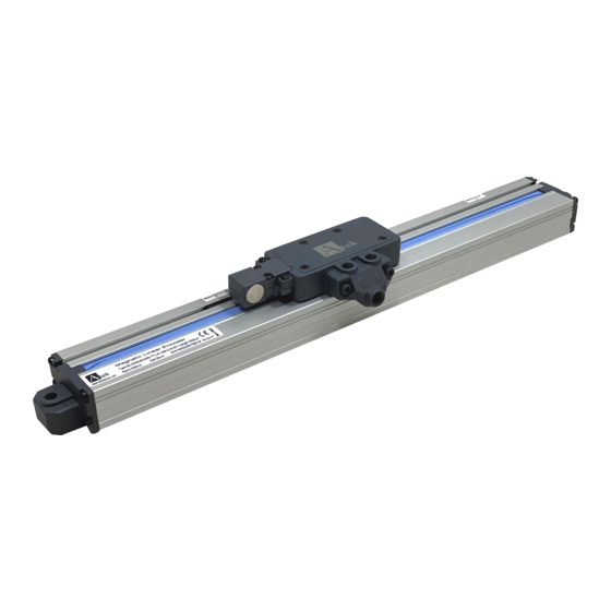
MLC 420
PORTABLE
REFERENCE POINT
S
INEAR
CALES
OPERATION
MANUAL
Advertisement

Summary of Contents for Atek MLC 420
- Page 1 MLC 420 PORTABLE REFERENCE POINT AGNETIC INEAR CALES • Incremental Encoder Output A, B, Z, / A, / B, / Z OPERATION • Portable Reference Point • Stroke Values up to 2000 mm • Socket Building • Perfect Retention System MANUAL •...
- Page 2 KK-MLC.010 19.02.21 Rev No:3...
- Page 3 WARNINGS 1. Connections must be completed by only authorized personnel. 2. Consider the warnings when completing the connections and using the scale. 3. Pay attention about the sensors power supply. (For TTL sensor max. 5V, for Push-Pull sensor max. 30V). Don’t energize the scale before all connections completed. 4.
-
Page 4: Product Code
On the other hand, the all precautions that is caused by machine are taken. Thanks to the Ergonomic design , cable output don’t block the scale and works in a stability. Thanks to the reference point, the side of the MLC 420 that is send by production as a left or right can be changed by user. -
Page 5: Technical Specification
TECHNICAL SPECIFICATION Technical Specification - 25 to 85 °C Operation Temperature Storage Temperature - 40 to 100 °C Protection Class IP65 Body Aluminum Magnetic Tape Type Reading Tape Distance 1,5 mm Opertaion Speed 3 m/s max. Connection D-Sub 9 Pin, 5 or 8 x 0,14 mm shielded cable Accuracy ±... -
Page 6: Power Supply
4. C ONNECTION 4.1. Pin Connections In the below table the cable color of the sensor output signals is given. If the control circuit is suitable in the Line Driver sensors the output signal inverts (/A, /B, /Z) must be included in the system. - Page 7 4.2. Reference Point Changing ( Right/ Left Changing ) MLC 420, thanks to the movable reference point you can change the factory output directions. For example the scales which is produced as right side can be return to the left side scale.
- Page 8 4.3. Montage Installation the MLC 420 is an important point in terms of the proper system function. The reader head is bearded in the profile, the distance between the profile and reader head is constant. The parallelism between the reader head and profile should stay same during the whole distances.
- Page 9 *Other Socket Connections S41 Socket S87 Socket Pin Number Cable Color Signal Pin Number Cable Color Signal POWER SUPPLY POWER SUPPLY BLACK GROUND BLACK GROUND YELLOW BLUE PINK YELLOW GREEN WHITE WHITE GREY GREY PINK BLUE GREEN S86 Socket S71 Socket Pin Number Cable Color Signal...
- Page 10 S57 Socket Pin Number Cable Color Signal YELLOW BLUE PINK GREY BLACK GROUND GREEN WHITE POWER SUPPLY S43 Socket Pin Number Cable Color Signal YELLOW BLUE GREEN WHITE PINK GREY POWER SUPPLY BLACK GROUND SHIELD KK-MLC.010 19.02.21 Rev No:3...
- Page 11 KK-MLC.010 19.02.21 Rev No:3...
- Page 12 ATEK ELEKTRONİK SENSÖR TEKNOLOJİLERİ SANAYİ VE TİCARET A.Ş. Gebze OSB, 800. Sokak, No:814 Gebze/KOCAELİ/TURKEY Tel: +90 262 673 76 00 Fax : +90 262 673 76 08 Web: www.ateksensor.com E-Mail: info@ateksensor.com KK-MLC.010 19.02.21 Rev No:3...
Need help?
Do you have a question about the MLC 420 and is the answer not in the manual?
Questions and answers