Table of Contents
Advertisement
Advertisement
Table of Contents

Related Manuals for Bay-Tek quik drop


Summary of Contents for Bay-Tek quik drop
- Page 1 SERVICE MANUAL...
-
Page 2: Factory Contact Information
FACTORY CONTACT INFORMATION BAY TEK ENTERTAINMENT 1077 East Glenbrook Drive Pulaski Industrial Park Pulaski, WI 54162 USA SIGN UP TO RECEIVE OUR E-MAILS! Stay up to date on the latest game information, new products launches, early notification of parts specials, updates of retro fit parts, software upgrades, best practices and more! Visit baytekent.com and enter your email to sign up! You can also register your new game at baytekent.com/register SALES... -
Page 3: Table Of Contents
TABLE OF CONTENTS FACTORY CONTACT INFORMATION ……..…………………………. 2 TABLE OF CONTENTS...……………………………………………….. 3 WELCOME TO Quik Drop ……………………...………………………. 4 GAME SPECIFICATIONS ……………………………………….……… 5 SAFETY PRECAUTIONS ……………………………………………… GAME SET UP ………………………………………….……………. 6 - 8 HOW TO PLAY ……………………..……………….…………………… 9 MAIN MENU FUNCTIONS ……………………………………………. -
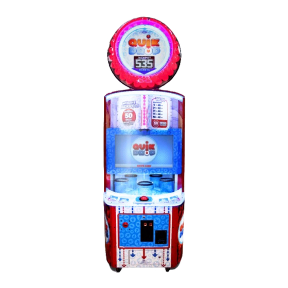
Page 4: Welcome To Quik Drop
WELCOME TO QUIK DROP GAME INSPECTION Please inspect the game for any damaged, loose, or missing parts. If damage is found, please contact your freight carrier first. Then, contact Bay Tek Entertainments’ Service Department at (920) 822-3951 Ext. 1102 Or email us at service@baytekent.com for further assistance. -
Page 5: Game Specifications
GAME SPECIFICATIONS WEIGHT POWER REQUIREMENTS NET WEIGHT 650 lbs. 295 kg INPUT VOLTAGE 115 VAC 220 VAC SHIP WEIGHT 740 lbs. 336 kg GAME DIMENSIONS INPUT FREQUENCY 60 Hz 50 Hz WIDTH 38 1/2" 98 cm MAX OPERATING CURRENT DEPTH 43"... -
Page 6: Game Set Up
QUIK DROP SETUP The game will arrive on 2 pallets. Please inspect the pallets for shipping damage and report immediately to the freight company if any damage is found. There will be about 1/2 hour of assembly time needed. Tools Needed: 1 step ladder (6 foot) 9/16”... - Page 7 QUIK DROP SETUP Secure the marquee in place by threading 4 bolts (A5BOHH090), 4 lock washers (A5WALO010) and 4 washers (A5WAFL050) up into the marquee. Tighten all 4 bolts using a 9/16” wrench. A5BOHH090 A5WALO010 A5WAFL050 Pull the 7 cables down from the marquee into the lower cabinet.
- Page 8 Plug one end into the back of the cabinet and the other into the wall. Open the front door of the cabinet and flip the rocker switch on the power strip to power on game. You’re ready to Quik Drop!
-
Page 9: How To Play
HOW TO PLAY Press the button to drop 50 balls into the moving buckets before time runs out. Rapid fire is encouraged! Win tickets for the balls caught. Catch all 50 balls in the allotted time to win the progressive jackpot! -
Page 10: Main Menu Functions
MAIN MENU FUNCTIONS The Menu and Menu Select buttons are located inside the center lower front door. Hold the MENU button down for 1 second to open the main menu on the display. Press MENU to scroll through the options, and MENU SELECT to change the settings. -
Page 11: Game Menu
GAME MENU Scroll through the options by pressing the “MENU” button. Change selection with the “SELECT” button. Scroll to “BACK” and press the “SELECT” button to go back to the main menu. Default settings are highlighted in yellow below. TIME PER GAME Sets the time in seconds of a game MAX TIME Sets the maximum time in seconds of a game... -
Page 12: Payout Menu
PAYOUT MENU Scroll through the options by pressing the “MENU” button. Change selection with the “SELECT” button. Scroll to “BACK” and press the “SELECT” button to go back to the main menu. Default settings are highlighted in yellow below. CREDITS PER GAME Sets the amount of credit pulses needed to start a game. -
Page 13: Ticket Bucket Menu
TICKET BUCKETS MENU Ticket Values can be changed to affect average tickets per game payout. High Range of balls caught for each level can be adjusted, Low Range and will automatically populate the can not be Low Range for the following level changed to avoid overlap. -
Page 14: Statistics
STATISTICS Scroll through the options by pressing the “MENU” button. Change selection with the “SELECT” button. Scroll to “BACK” and press the “SELECT” button to go back to the main menu. TOTAL GAMES PLAYED Shows the total number of games played since last Reset. TOTAL PAYOUT Shows the total number of tickets payed out since last Reset. -
Page 15: Diagnostics
DIAGNOSTICS The top section of diagnostic data shows actual “live” status of game sensors and switches. Scroll through the options by pressing the “MENU” button. Change selection with the “SELECT” button. Scroll to “BACK” and press the “SELECT” button to go back to the main menu. -
Page 16: Error Codes
ERROR CODES The Quik Drop game is equipped with error-sensing software. When this Game Error screen appears, the game is not functioning normally. Sensors need to be cleaned occasionally to prevent misreading due to dust build up. A simple wipe of the sensors with a Q-tip or Kleenex will be enough to clear most sensor issues. - Page 17 ERROR CODES AACB3404A Ball Count Sensor 12 Volts DC power between The game knows it is not seeing any balls dropping out of the tube the Red and Black wires. Normally 3.3 VDC between Clean or replace Ball Count Sensor in the center of the game at the Black and White wires (LED is OFF) bottom of the tube.
-
Page 18: Sensor Locations
SENSOR LOCATIONS... -
Page 19: Card Swipe Installation
CARD SWIPE SYSTEM INSTALLATION Option #1: This ICL connector is to be used for New card swipe systems may come with a standard card swipe systems 9 pin Molex connector. Simply unplug this connector and plug into your card swipe reader. AACE5815 Coin Switches and Lights AACBL4A-DOOR... -
Page 20: How To Adjust Marquee Height
HOW TO ADJUST MARQUEE HEIGHT Each side of the marquee support is equipped with a height adjustment system, allowing flexibility in height from 109” to LOOSEN 123” Remove casters before installing marquee for 9 foot ceiling height. (107”) Loosen the upper bolts on the both sides and remove the lower bolts using a 9/16”... -
Page 21: How To Access Top Ball Fill Motor & Sensor
HOW TO ACCESS TOP BALL FILL MOTOR & SENSOR Using a ladder, carefully unlock the upper back door of the marquee. This provides access to the Top Auger Motor and Encoder Sensor. To change motor or sensor: Remove the 4 pan head bolts (A5BOPH220) with split washers (A5WASI020) using a Phillips screwdriver. -
Page 22: How To Replace Monitor
HOW TO REPLACE MONITOR Unplug the game from the wall and remove the back door. Remove the 8 black 8 screws (A5SCPH101) using a # 2 square bit and remove the plexi shield. Reach into hole and unplug the monitor power and unscrew the DVI cable from the monitor. -
Page 23: How To Replace Ball Drop Solenoid
HOW TO REPLACE BALL DROP SOLENOID Remove the 5 flat head bolts (A5BOBH030) using a 5/32” Allen wrench from the side rail. Bend and flex the front plexi around the drop button and out of the way. Remove the 4 small screws (A5SCPH030) using a small Phillips screwdriver. -
Page 24: How To Replace Carousel Motor
HOW TO REPLACE CAROUSEL MOTOR Unplug the game from the wall and remove the back door. Remove the 8 black 8 screws (A5SCPH101) using a # 2 square bit and remove the plexi shield. Remove the motor bracket from game by removing the 4 nuts using a 7/16”... -
Page 25: How To Access Blower
HOW TO ACCESS BLOWER Unplug the game from the wall and remove the back door and remove all the red balls from cabinet. Remove the 2 of 1 5/8” black bugle screws (A5SCFH050) on the wood piece that shows “Blower Access” using a # 2 square bit. This wood can now be removed from the cabinet. - Page 26 HOW TO REMOVE BLOWER (CONTINUED) There is a wood block attached to the back wall of the cabinet. This must be removed to remove the blower/wood assembly. Remove these 3 of 1 1/4” bugle screws (A5SCFH040) using a # 2 square bit.
-
Page 27: How To Change Fuses In Marquee
HOW TO CHANGE FUSES IN MARQUEE carefully unlock the Unplug the game from the wall, use a ladder to upper back door of the marquee. Locate the AACE5858 cable. The 5 amp fuses are located inside the black plastic housings. Fuses are part # A5FUSE11 HOW TO CHANGE LIGHTS IN MARQUEE The marquee will have to removed from the game to change the LED lights inside. - Page 28 CIRCUIT BOARD PINOUT AACE5822 AACE5815 Sensors, Motor Coin Door Driver Board Signal, AACE5820 Low Ticket Menu Buttons & Counter AACE5818 AACE5524 Ticket Dispenser Communication with Motherboard AACE5809 AACE5823 Bill Acceptor Carousel Motor, AACE5831 Ball Drop Solenoid Carousel Encoder & LED’s Sensor AANEWGEN1-PJ/RBN AACE5815...
- Page 29 Quick Drop Motherboard Communication Wiring Diagram on MB11 games manufactured after 2/5/18 Two LED’s will flash rapidly when communication is established AACE5524 Communication cable A5CORD14 from blue J16 on Newgen USB cable from board to Communication Motherboard to Board. Communication MB11 Motherboard must have...
- Page 30 Quick Drop Motherboard Communication Wiring Diagram on MB9 games manufactured before 2/5/18 RX is receiver communication from Newgen Board. It should be flashing rapidly and dim. TX is transmitter communication from Motherboard. It should be flashing rapidly and dim. Power comes from Newgen Board. AACE5524 LED should be on if power is on.
- Page 31 AC IN, POWER SUPPLY WIRING DIAGRAM Right Instruction Playfield Left Instruction LED lighting Illumination LED lighting AAMB11-HD AACB3906 Motor Driver Board AACE5840 AACE5840 AACE5808 Power Cable to SATA Hard AACE9736 A5HD1800 SATA Hard AACE5852 AACE5812 AACE5829 Drive AACE5940 AACE5838 12 VDC To Power Supply Marquee AAPS1011-QD...
- Page 32 JACKPOT DISPLAY, SPEAKER, CAROUSEL MOTOR & BALL DROP SOLENOID A5LD1058 Jackpot Display AACE5841 A5MO5800 Carousel Motor Normally 10 secs per 5 Volts from Power Supply revolu)on. (6 RPM) AACE3892 1.2 Ohms AACB3904 Ground AACE5855 Wire Spli0er Board AACE5842 AACE5823 3.5 Amp Fuse (A5FUFB010) AACE5859 5 Amp Fuse...
- Page 33 SENSORS & AUGER MOTOR WIRING DIAGRAM AACB3404A Ball Fill Sensor 12 Volts DC power between the AAMO5801 Black and Red wires. Ball Fill Sensor 12 Volts DC power between Ball Dispense When Blocked - 0 VDC between the Red and Black wires. Motor the Black and White wires.
- Page 34 COUNTERS, MENU BUTTONS, BALL DROP BUTTON, AUGER SENSOR, & BLOWER SIGNAL WIRING DIAGRAM Ticket Counter AACO3325 Game Counter AAPB2700 Menu To J25 Button connector AACE5820 AAPB2700 Menu Select AANEWGEN1-PJ/RBN To J24 connector A5PB4600 Ball Drop Button To Top Ball Feed Auger Encoder AACE5815 Sensor...
-
Page 35: Wiring Diagrams
MARQUEE LIGHTING, COIN MECH, & TICKET DISPENSER WIRING DIAGRAM AACE5848 LED’s in the back of AACE5818 Marquee Low Ticket Switch Wired Normally Open Part # AASW200 AACE5822 AACE5849 LED’s around AACE5830 back of Marquee AACE5850 LED’s around Blue To J21 side of Marquee colored Connector... -
Page 36: Troubleshooting Guide
TROUBLESHOOTING GUIDE Troubleshooting Strategy Use common sense and a systematic method of troubleshooting to determine the exact problem, probable cause and remedy. Use the process of elimination to find the faulty component. Always check for the simple and obvious causes first such as unplugged, loose or broken wires and bad sensors, bent, pinched, stuck or jammed components. - Page 37 TROUBLESHOOTING GUIDE Problem Probable Cause Remedy LED lighting LED’s receive 12 Volts DC Check for proper connection and reseat cables from inside cabinet from power supply. power supply to LED strip. Refer to wiring diagram. left and right Cables # CE5840 and CE5852 instruction panels not Faulty LED light.
- Page 38 TROUBLESHOOTING GUIDE Problem Probable Cause Remedy Light inside drop Light receive signals from Check for proper connection and reseat cables from button not I/O Newgen Board I/O Newgen Board to lights. Refer to wiring diagram working Cables # CE5815 Light should be solid Faulty light bulb Replace light bulb.
- Page 39 TROUBLESHOOTING GUIDE Problem Probable Cause Remedy Opto Sensor on ticket Blow dust from sensor and clean with Tickets do dispenser dirty. isopropyl alcohol. not dispense or Wrong Faulty ticket dispenser. Replace with working dispenser to isolate the Tickets on amount problem.
- Page 40 TROUBLESHOOTING GUIDE Problem Probable Cause Remedy Check for DC voltage to the The voltage sent to motor will vary to keep the motor Carousel Motor motor. It should be 8-12 VDC at 6RPMs. If voltage is present and the motor does not not turning turn, replace motor.
- Page 41 TROUBLESHOOTING GUIDE Problem Probable Cause Remedy Check green If green LED is ON, then refer to AC voltage problem below LED on AC DC voltage If green LED is OFF: driver board. problem Check for disconnected, loose or broken wires from Newgen Board Blower It should be ON to AC Driver Board.
- Page 42 TROUBLESHOOTING GUIDE Problem Probable Cause Remedy The tube is full of balls. Game is operating normally. The motor will not turn if the tube is full. Game thinks the ball tube Refer to “How to Access Ball Tube Fill Sensor” The Ball Tube Fill Sensor is is full.
- Page 43 TROUBLESHOOTING GUIDE Problem Probable Cause Remedy Check for 12 volts to sensor There should always be 12 volts on the orange and Bad Ball Score and 3.3 volt signal return. green wires for power in. Sensor Signal wires have 3.3 volts on the white and green wires when sensor is clear, and 0 volts when blocked.
- Page 44 If the communication error is displayed, please follow the below instructions for the 2 versions of communication used by Quik Drop. Choose the diagram that matches your game and re-seat connections, replace parts as needed.
-
Page 45: Power Supply Diagnostics
POWER SUPPLY DIAGNOSTICS 1.) Verify AC power to game. Check power strip in front door. The rocker switch should be illuminated. 2.) Check connection to power supply. 3.) Ensure Power Supply switch is set to 115V (or 230V) (Some model power supplies may not have this) 4.) Ensure Power switch is on. -
Page 46: How To Update Software
HOW TO UPDATE SOFTWARE Software Update Instructions for Quik Drop It is possible to change software in 2 different locations: 1.) Motherboard Software is a SATA drive 2.) Newgen software is a file to be uploaded via USB thumb drive Your software update may include only one of these, or both, depending on circumstance. -
Page 47: Bill Acceptor Diagnostics
If your games have a center link console attached to 2 games: Set both Dipswitches to OFF on the control board. In the rare event that you have 3 Quik Drop games linked together with 2 link kits: Set one board with Dip #1 ON, #2 OFF... -
Page 48: Parts List
PARTS LIST PART # DESCRIPTION PART # DESCRIPTION A5ME1878 Metal,3/8 Diax4"Lg Rod AABA5802-P70 Set Of 70 Red Balls A5BA5801 Ball, Red,Smooth, 3" A5ME5800 Metal, Front Corner AABK1013 Bracket, Pushbutton/Counters A5ME5801 Metal, Side Corner A5BR1001 Bearing A5ME5802 Metal, Window Brkt A5BR5800 Bearing, Solenoid Guide A5ME5803 Metal, Ball Shear Plate... - Page 49 PARTS LIST PART # DESCRIPTION PART # DESCRIPTION AACE5851 Cable, Ball Fill Sensor A5CORD1 Cord,Power,10' AACE5852 Cable, Ticket Bucket Light Power Jumper A5CORD14 Cord,3'usb R Angle, B to A Male AACE5853 Cable, Ball Auger Sensor Jumper A5CORD21 Cord, 3', 35mm Male To Male, Audio AACE5854 Cable, Ground Strap A5CORD5...
-
Page 50: Parts Pictures
A5CEAU010 A5CN1031 PARTS PICTURES AABA5802-P70 A5BA5801 AABK1013 A5BR1001 A5CA1005 A5CB1499 A5CH1800 A5CL1004 A5CL3200 A5CO4203 A5DE0042 A5DE5800 A5DE5801 A5DE5802 A5DE5803 A5DE5804 A5DE5805 A5DE5806 A5DE5808 A5DE5809 A5DE5810 A5DE5811 A5DE5812 A5DE5813 A5DE5814 A5DE5815 A5DE5815-CEC A5DE5816 A5DE5817 A5DE5819 A5FI9010 A5FO5800 A5GR5800 A5HO1003 A5LI0003 A5LK2001 A5LK5002 A5ME1878 A5ME5800... - Page 51 PARTS PICTURES A5SP5801 A5TR5800 A5TT4000 AAPS1011-QD A5CORD1 A5CORD14 A5CORD21 A5CORD5 A5SP4100 AACBL4A-DOORA AACE1715 AACE3892 AACE5523 AACE5524 AACE5802 AACE5803 AACE5808 AACE5809 AACE5810 AACE5811 AACE5812 AACE5815 AACE5816 AACE5818 AACE5819 AACE5820 AACE5822 AACE5823 AACE5825 AACE5828 AACE5830 AACE5831 AACE5832 AACE5835 AACE5838 AACE5840 AACE5841 AACE5843 AACE5844 AACE5845 AACE5846...
-
Page 52: I/O Aux Board Pinout
PARTS PICTURES A5PB4600 AABL3201-QD A5MO3200 A5MO5800 AASW200 A5TD1 A5LD1058 AACO3325 AAMO5801 AAPB2700 AASO5800 AACB2204 A5CE2300 A5CEAU010 A5CB0232 AABD5029-A AACB3404A AACB3904 AACB3906 AACB4401 AAMB11-HD AANEWGEN1-PJ/RBN I/O AUX BOARD PINOUT... -
Page 53: Decal Diagram
DECAL DIAGRAM... -
Page 54: Maintenance Log
REPAIR/MAINTENANCE LOG If you need to make repairs or order replacement parts it is a good idea to keep a log. Below is a chart you can use to track repairs and maintenance. DATE MAINTENANCE PERFORMED PARTS ORDERED MISC. NOTES... -
Page 55: Technical Support
TECHNICAL SUPPORT Excellent customer service is very important to Bay Tek Entertainment! We know that keeping your games in great operating condition is important to your business. When you need us, we are here to help. You can call us for free technical assistance, and you can count on us to have parts on-hand to support your game. -
Page 56: Warranty
WARRANTY OPTIONS Bay Tek Entertainment warrants to the original purchaser that the game will be free of defects in workmanship and materials for a period of 6 months from the date of installation. Register your new game for an extra 3 months on your warranty. Log on to : http://www.baytekent.com Then click on the Register tab.
Need help?
Do you have a question about the quik drop and is the answer not in the manual?
Questions and answers