Table of Contents
Advertisement
Quick Links
Advertisement
Table of Contents

Related Manuals for ABB REL301


Summary of Contents for ABB REL301
- Page 2 Electrostatic discharge precautions should be observed when handling modules or individual components. ABB does not assume liability arising out of the application or use of any product or circuit described herein. ABB reserves the right to make changes to any products herein to improve reliability, function or design. Spec- ifications and information herein are subject to change without notice.
- Page 3 I.L. 40-386.3 PREFACE Scope This manual describes the functions and features of the REL 301(Non-pilot Relay System) and REL 302 (Pilot Relay System). It is intended primarily for use by engineers and technicians involved in the installation, testing, operation and maintenance of the REL 301/302 system. Equipment Identification The REL 301/302 equipment is identified by the Catalog Number on the REL 301/302 chassis name- plate.
- Page 4 I.L. 40-386.3 TABLE OF CONTENTS ECTION RODUCT ESCRIPTION ..........1-1 NTRODUCTION REL 301/302 F .
- Page 5 I.L. 40-386.3 LIST OF FIGURES PAGE ECTION REL 301/302 R FT-42 C )....1-1 ELAY SSEMBLY IN PHOTO REL 301/302 L 2) .
-
Page 6: Table Of Contents
I.L. 40-386.3 CO-7 C ........2-44 URVE HARACTERISTICS CO-8 C... - Page 7 I.L. 40-386.3 REL 301 AND REL 302 Version 1.7 Features added and improvements made to Version 1.11 REL 301 AND 302 Modified Ground distance units from partially crossed-polarized mho to self-polarized mho units for Zone1, Zone2, Zone3, and Pilot zone. The modification requires the addition of one reverse reach setting for each zone.
- Page 9 I.L. 40-386.3 1. 2. REL 301/302 FEATURES 1.2.1 Standard Features for REL 301 (Non-Pilot) • 3-Zone distance phase and ground relay, with reversible Zone3 phase and ground; 4 impedance units per zone: 3 phase-to-ground; 1 phase-to-phase. • T1 timer (0 to 15 cycles) •...
- Page 10 I.L. 40-386.3 1.2.2 Standard Features for REL 302 (Pilot) • All features listed as standard for the REL 301 are included in the REL 302 also • Independent pilot phase and ground distance units • Permissive Overreach Transfer Trip (POTT) /Simplified Unblocking •...
-
Page 11: Section 5 Filter ( Input ) Module
I.L. 40-386.3 • PT Module: Consisting of 3 voltage transformers for V and V • CT Module: Consisting of 4 current transformers for IA, IB, IC and IP, where IP is used for zero- sequence dual-polarizing ground current measurement. • Filter Module: Consisting of the anti-aliasing filters for the seven inputs from the vt and ct mod- ules, the multiplexer to the A/D converter, the A/D converter itself, and the Opto- isolator for the input contacts. - Page 12 I.L. 40-386.3 The REL 302/302 software which does the sampling has 8 states; these states corre- spond to the sampling rate (8 samples per cycle). Movement from state to state is con- trolled by a timer. The timer is loaded with a state time at the beginning of the state.The code executed within a state should be completed before the timer expires.
- Page 13 I.L. 40-386.3 current ground-fault recognition at the remote terminal, allows immediate tripping to take place at the terminal. 1.4.4 Self-checking Software REL 301/302 continuously monitors its ac input subsystems using multiple A/D con- verter calibration-check inputs, plus loss-of-potential and loss-of-current monitoring. Failures of the A/D converter, or any problem in a single ac channel which unbalances non-fault input, causes an alarm.
- Page 14 I.L. 40-386.3 1. 6. SPECIFICATIONS 1.6.1 Technical Operating Speed 12 ms (minimum) (from fault detection to trip contact close (60 Hz) 26 ms (typical) ac Voltage (VLN) 60 Hz 70 Vrms 50 Hz 63.5 Vrms ac Current (In) 1 or 5 A Rated Frequency 50 or 60 Hz Maximum Permissible ac Voltage (Thermal Rating)
- Page 15 I.L. 40-386.3 All other contacts are “Non-trip” rated. • Non-Trip Contacts • 1A Continuous • 0.1A Resistive Interrupt Capability Supports 1000 Vac across open contacts Contacts also meet IEC - 255-6A, IEC - 255-12, IEC -255-16, BS142-1982. • RS-232C PONI - for single point computer communications ®...
-
Page 16: Test
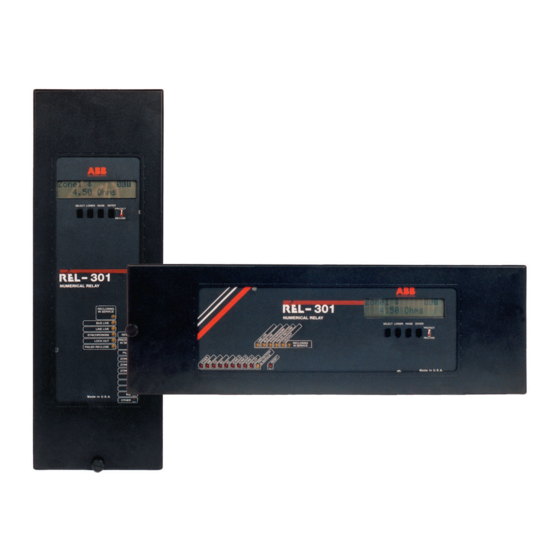
I.L. 40-386.3 1.6.6 REL 301/302 Catalog Numbers M V 3 B 1 R N 5 C L MOUNTING Horizontal * - - - - - - - - - - - - - - - - - - - - - H Vertical - - - - - - - - - - - - - - - - - - - - - - - V TRIP 3-Pole Trip - - - - - - - - - - - - - - - - - - - - - - -3... - Page 17 Sub 2 2682F39 Sheet 1 of 2 Figure 1-2. REL 301/302 Layout. (Vertical)
- Page 18 Sub 2 2682F39 Sheet 2 of 2 Figure 1-3. REL 301/302 Layout. (Horizontal)
- Page 21 I.L. 40-386.3 -Initialization Mode = POWER -Self-Checks Background START Sample V and I dc Offset Correction Compute V and I Phasors Using Fourier Algorithm Mode? Fault Relaying Calculations: Zone1 and Pilot Zone Background Pilot Logic and Channel Control Disturbance Ι? Mode = ∆...
- Page 22 I.L. 40-386.3 Section 2. FUNCTIONAL DESCRIPTION 2. 1 INTRODUCTION Both the REL 301/302 relay systems detect faults in three zones of, phase and ground distance Zones1 and 2 are forward set; Zone3 can be set to forward or reverse. The fault locator can be set to indicate fault distance in miles or kilometers.
-
Page 23: For
I.L. 40-386.3 is the direction where tripping takes place; the “reverse” reach is then in the forward line direction.) – – ∠ GANG PANG ----------------------- - – -- - I Where V or V or I zero and positive sequence line impedance in relay ohms Zone forward and reverse reach settings in secondary ohms of Z1L, for ph- G fault (both are in angle PANG) These units are directionally supervised by FDOG (RDOG for reverse Zone3). - Page 24 I.L. 40-386.3 2.2.3 Phase-to-Phase Fault The phase-to-phase (ØØ) unit (Figure 2-4) responds to all phase-to-phase faults, and some single-phase-to-ground faults. Equations (5 and 6) are for operating and refer- ence quantity, respectively. They will produce output when the operating quantity leads the reference quantity.
- Page 25 I.L. 40-386.3 A two-out-of-three “leading phase blocking” logic is included for solving the overreach problem of the single-phase ground distance units, which may respond to a two phase-to-ground (ØØG) fault. The high-speed trip (HST) signal also is connected to the reclosing initiation logic. Both Zone1 phase and Zone1 ground function(s) can be disabled by setting the Zone1Ø...
- Page 26 I.L. 40-386.3 If T2ø type and/or T2G Type was selected as Torque Control: (selection of the CO Inverse time settings) Table 5: T2ø CV and C0-2; C0-5; C0-6; C0-7; T2G CV C0-8; C0-9; C0-11 Table 6: T2ø PkUp and 0.5 to 10.0 Amperes T2G PkUp 0.5 to 10.0 Amperes Table 7:...
- Page 27 I.L. 40-386.3 Z1 reach by the microprocessor, and one is the normal Z1 reach. A single shot instan- taneous reclosing device should be used when applying this scheme. The targets Zone1Ø/Zone1G will indicate either Z1 trip and/or Z1E trip operations. The other functions (e.g., Z2T, Z3T, ac trouble monitoring, overcurrent supervision, Inst., CIF Trip (CIF), unequal-pole closing load pickup control, LL trip, etc.) would remain the same as in the basic scheme.
- Page 28 I.L. 40-386.3 voltage and/or zero sequence current) or Negative Sequ (NSEQ) (negative sequence voltage and negative sequence current) for polarization (see 2.4.11, Selectable Ground Directional Unit, Zero Sequence / Negative Sequ/Dual Polariz). 2.4.3 Loss of Potential Supervision The ac voltage monitoring circuit is called loss-of-potential (LOP) circuit. In order to prevent undesirable tripping due to the distance unit(s) pickup on loss-of-potential, the following logic is used: <7Vac) or (3Vo>7Vac) and not ∆I or not (3I...
- Page 29 I.L. 40-386.3 AND-23; the output signal of AND-23 starts the 500/500 ms timer. The timer output turns “ON” the non-memory LOI indicator, which is shown in the Metering mode, and drops out the AL1 relay (Failure Alarm). If the LOI condition exists and LOI Blk (LOIB) is set at YES, the trip will be blocked after the 500 ms timer times out.
- Page 30 I.L. 40-386.3 2.4.8 Unequal-Pole-Closing-Load Pickup Logic The ground units may pick up on a condition of load pickup with unequal breaker pole closing. The high speed ground units (Zone1G, FDOG and PLTG) should be supervised under this condition. This can be achieved (as shown in Figure 2-16) by inserting a 0/ 20 ms timer (controlled by the 52b signal) to supervise the Zone1G trip AND-3.
- Page 31 I.L. 40-386.3 ∆I i f [ ( 3I - ( 3I ] > 0 . 5 amp. (K - 1) n Whe r e n = 1, 2 , 3 , 4 , 5, 6, 7, 8 an d K = nu m be r of c y cl e s 2.4.11 Ground Directional Polarization Selection The ground directional unit Dir Type (DIRU) contains three selections Zero Sequence (ZSEQ), Negative Sequ (NSEQ) and Dual Polariz (DUAL), which determine the operation...
- Page 32 I.L. 40-386.3 The program is further controlled by the RI Type setting: RI Type setting NO RI: 3PRN provides no output, therefore, will not operate RI2. RI Type setting ØG RI: 3PRN will provide output “1” on single-phase-to-ground fault only and will operate RI2.
-
Page 33: Polarizing
I.L. 40-386.3 unless 21BI operates. This prevents operation of the distance relay on load. The OSB signal is also applied to the reclosing logic for initiating RB. Blinder Line Polarizing Operating ° ° Left -j(V XG + I X R C (PANG–90 ) I X (PANG–90 °... - Page 34 I.L. 40-386.3 Zone2, Zone3 (Z2Z3) — start data taken if Zone2 or Zone3 units pick up, or any trip action occurs. ∆V or ∆I (∆V∆I) — start data taken if ∆I, ∆V, Zone2 or Zone3 units pick up, or any trip action occurs.
- Page 35 Pilot trip is provided, however, if the tripping distance relay(s) op- erate during this short time period between loss-of-channel and pilot trip lockout. ABB type TCF-10B receiver provides this logic; it provides a 150 ms trip window, then au- tomatic lockout after loss-of-channel.
- Page 36 I.L. 40-386.3 † (2) Echo Keying Since the POTT and the Simplified Unblocking schemes require the receiving of a permissive signal from the remote end, for pilot trip, provision should be made for covering the condition when the remote breaker is opened. When the remote breaker is opened, the inputs of AND34B (Figure 2-22) will satisfy the NOT FORWARD, NOT REVERSE and 52b=1 conditions.
- Page 37 I.L. 40-386.3 should be set to “Reverse Dir” and Zone3Ø (Z3P) , Z3G should be set to 100% of the line impedance. † Channel Simulation The test function selection provides the capability to simulate the TK switch function for keying action via OR-18 and AND-35 without the operation of pilot relay units, and to simulate the RS switch function for receiving of a trip or unblocking frequency sig- nal action without the operation from the remote transmitter.
- Page 38 I.L. 40-386.3 NOTE: For open breaker condition, the echo keying will not work due to lack of the “SEND” signal from the remote terminal for an end Zone fault. The remote terminal relies on Zone2 to clear the fault. c. Programmable Reclosing Initiation (Figure 2-19) Same as for POTT scheme.
- Page 39 I.L. 40-386.3 AND-51, AND-50, OR-18, and AND-35, sending a blocking signal to the other terminals. The local receiver receives the blocking signal, disables the operation of AND-47; therefore, AND-48 will produce no carrier trip signal for AND-52. b. Carrier Keying Logic Reverse fault keying (Figure 2-24) For a reverse fault, the ∆I and ∆V as well as the local reverse-looking relay Zone3Ø)(R)/Z3G(R) or RDOG sees the fault, operates the CARSND relay and...
- Page 40 I.L. 40-386.3 c. Carrier Receiving Logic (Figure 2-24) Carrier signal from the receiver output will be directly applied to AND-47 to disable the pilot tripping function. d. Channel Indication (not shown in Figure 2-24) Since the carrier channel turns “ON” for external faults only, the channel indicators †...
- Page 41 I.L. 40-386.3 function (FDOG) works in conjunction with the pilot ground distance unit. The FDOG directional unit is determined by the setting of Dir Type (DIRU) (Zero Sequence /Nega- tive Sequ / Dual Polariz). Refer to Section 3.4.11 for the setting of Dir Type (DIRU). FDOG is supervised by the Iom setting.
- Page 42 I.L. 40-386.3 system security. For a fault which can be detected by relays at two terminals, AND-55 logic can be satisfied, then pilot trip will be performed via the logic in the usual way. 2.5.6 Weakfeed Trip Application a. Block/Weakfeed The logic for a weakfeed terminal is not required for the (Blocking) system be- cause the (Blocking) system requires no permissive trip signal from the remote end, even though the remote end is a weakfeed terminal.
-
Page 43: Trip
I.L. 40-386.3 Weak end trip on internal fault (Figure 2-30) The output of AND-65 (start echo keying) together with no output from OR-40 (pilot trip relays), and with output from OR-44 (low voltage condition) will satisfy AND-66; weakfeed trip will be performed after 50 ms via OR-2. The timer delay is for coordination because the voltage trip units are non-directional. - Page 45 I.L. 40-386.3 Zone2 G Zone3G R* Zone1 G Ang Pos Zone3 G* Zone1G R Zone2G R * Zone3 set in reverse direction NOTE: ZoneX G = “TRIP DIRECTION’ Reach ZoneXG R = “NON-TRIP” Reach Figure 2-2 Mho Characteristic for Phase-Ground Faults 2-24 (10/94)
- Page 47 I.L. 40-386.3 INPUTS OUTPUT ELECTROMECHANICAL CONTACT EQUIVALENT INPUTS OUTPUT SIGNAL ON ALL INPUTS REQUIRED TO PROVIDE AN OUTPUT Notes: I – Active state of a signal (may be defined as positive or negative voltage or current) 0 – Inactive state of a signal (reference) –...
- Page 50 I.L. 40-386.3 Sub 1 9655A81 Figure 2-9. Inverse Time Overcurrent Ground Backup Logic Sub 3 9655A82 Figure 2-10. Loss-of-Potential Logic (10/94) 2-29...
- Page 52 I.L. 40-386.3 Sub 1 9658A85 Figure 2-13. Overcurrent Supervision Sub 1 9657A58 Figure 2-14. Instantaneous Overcurrent Highset Trip Logic (10/94) 2-31...
- Page 58 I.L. 40-386.3 Sub 2 9657A65 Figure 2-25. PLTG Supplemented by FDOG *Sub 1 9654A17 Figure 2-26. Power Reversed on POTT/Unblocking Schemes (10/94) 2-37...
- Page 59 I.L. 40-386.3 Sub 1 9654A29 Figure 2-27. Unequal Pole Closing on Fault Sub 1 9654A30 Figure 2-28. Additional Logic for POTT/Unblocking Schemes on 3-Terminal Line Application 2-38 (10/94)
- Page 61 Sub 6 1501B84 Figure 2-31. Reversible Zone3 Phase and Ground (Reverse Block Logic)
- Page 62 I.L. 40-386.3 Sub 2 619596 Figure 2-32. CO-2 Curve Characteristics (10/94) 2-41...
- Page 63 I.L. 40-386.3 Sub 2 619597 Figure 2-33. CO-5 Curve Characteristic 2-42 (10/94)
- Page 64 I.L. 40-386.3 Sub 2 619598 Figure 2-34. CO-6 Curve Characteristic (10/94) 2-43...
- Page 65 I.L. 40-386.3 Sub 2 619599 Figure 2-35. CO-7 Curve Characteristic 2-44 (10/94)
- Page 66 I.L. 40-386.3 Sub 2 619600 Figure 2-36. CO-8 Curve Characteristic (10/94) 2-45...
- Page 67 I.L. 40-386.3 Sub 2 619601 Figure 2-37. CO-9 Curve Characteristic 2-46 (10/94)
- Page 68 I.L. 40-386.3 Sub 2 619602 Figure 2-38. CO-11 Curve Characteristic (10/94) 2-47...
- Page 69 I.L. 40-386.3 Section 3. SETTING CALCULATIONS 3.1. MEASUREMENT UNITS AND SETTING RANGES DISTANCE MEASUREMENTS • Three variable mho phase-to-ground units and one variable mho phase-to-phase impedance unit per zone. Three Zones Phase and Ground Distance (Zone1, 2, 3): 0.01 - 50 ohms in 0.01 ohm steps for 5 A (ct type) 0.05 - 250 ohms in 0.05 ohm steps for 1 A (ct type) Any Zone (phase or ground distance) can be disabled •...
- Page 70 I.L. 40-386.3 • One inverse overcurrent ground unit with CO characteristics (see Figures 2-32 through 2-38) for ground backup: Pickup (0.5 - 4.0) in 0.1 A steps for 5 A (ct type). Choice of 7 time-curve families (CO-2, 5, 6, 7, 8, 9, 11 Characteristics), 63 curves per family.
- Page 71 I.L. 40-386.3 • Zero sequence impedance: / (pri) = 50∠73° ohms • Current Transformer Ratio (CTR): RC = 1200/5 = 240 (Set CTR = 240) • Voltage Transformer Ratio (VTR): RV = 600/1 = 600(Set VTR = 600) Relay secondary ohmic impedances are: = 15 ∠...
- Page 72 I.L. 40-386.3 If the calculated Zone1 impedance is 0.5 ohms (secondary) or less the line per- centage, used for the calculation, should be 70-75%. If the Source Impedance Ratio or SIR, (ratio of positive sequence source imped- ance to positive sequence line impedance) is in the range of 3-5 the line percent- age, used for the calculation, should be no more than 75%.
- Page 73 I.L. 40-386.3 3.2.4 Zone2 Distance Settings Generally, Zone2 reach is set for 100% of the protected line plus 50% of the shortest adjacent line. If the shortest (or only) adjacent line primary impedance is 20 ohms, then the Zone2 reach setting would be: Zone2 Ø...
- Page 74 I.L. 40-386.3 The medium set ground overcurrent unit is used for supervising the Zone1, Zone2 and Zone3 ground distance units, the forward directional overcurrent ground unit (FDOG). Gen- erally, it is recommended to be set 2 times the 3I0s setting. 3I0M = 2 x 3I0s = 1.0 The directional high set overcurrent phase and ground units (Inst.
- Page 75 I.L. 40-386.3 Set inner blinder to: x COS (90° - PANG)(1) This is the minimum permissible inner blinder setting when it is used to provide a restricted trip area for a distance relay. Another criterion that may be considered is based upon the rule of thumb that sta- ble swings will not involve an angular separation between generator voltages in ex- cess of 120°.
- Page 76 I.L. 40-386.3 NOTE: T2Ø Time and T2G Time are separate timers; they can have differ- ent time settings. Zone3 timer (T3Ø and T3G Time) settings would be similar to the above. For example, if T3 of 0.8 seconds is required, then the phase and ground Zone3 timers should be set as follows: T3Ø...
- Page 77 I.L. 40-386.3 The setting of ∆I, ∆V, for OSC is not recommended since data will NOTE: be collected for normal operations. 3.3.2 Fault Data (Flt. Data) Capture Setting Is for selecting one of the 3 ways (TRIP/Z2TR/Z2Z3) to initiate the fault data taken, where: TRIP –...
- Page 78 I.L. 40-386.3 The fault distance calculation is as follows: × ∠ FANG VT Ratio × Flt Dist ------------------------- - ------------------------------------------- - CT Ratio X / Dist Where Z is the secondary impedance magnitude, and FANG is the fault angle. 3.3.9 Distance Type (DistUnit) Setting Distance type has a selection of MILE and KM.
- Page 79 I.L. 40-386.3 The FDGT (FDOG trip delay timer) can be set from 0 to 15 cycles or block (BLK) as de- sired. It is recommended to set to 3 cycles or longer. Refer to Section 3.9 for the detailed FDGT information. 3.3.16 Distance/Overcurrent Individual distance and overcurrent logic can be disabled, if required by the applica- tion by setting the unit to Disabled:...
- Page 80 I.L. 40-386.3 3.3.23 Polarizing Settings Settings for the directional ground overcurrent polarization is controlled by the setting of Dir Type. It has 3 selections: Zero Sequence —Zero sequence voltage polarization. Negative Sequ—Negative sequence voltage polarization. Dual Polariz—Both zero sequence voltage and current polarization. 3.3.24 Overcurrent Ground Backup The overcurrent ground backup function provides seven sets of curves, which are similar to the CO curves, for backing up the ground distance protection.
- Page 81 I.L. 40-386.3 GBT Curve = Time curve dial setting (1 to 63). , K, C, P and R are constants, and are shown in T able 3-1 . Taking the CO-8 curve set as an example (see Figure 2-36), assuming that the maxi- mum 3Io of unbalanced load is 0.2A, the minimum ground fault current for a fault two buses away is 10A, and 0.7 seconds is required for coordination with current of 20 times the GB Pickup setting, then the settings of the ground overcurrent backup func-...
- Page 82 I.L. 40-386.3 field. The REL 301/302 clock will start at the time the enter button is pushed while the display is showing the minute value. 3.4. RECLOSE INITIATION MODE PROGRAMMING 3.4.1 For Non-pilot and Pilot Systems Select RI Type = OFF, 1PR, 2PR or 3PR, (See Table 3-2) Use one of the two (RI-1 or RI-2) output contacts for the reclosing initiation circuit Select one or all of the Fast RI, Zone2 RI, and/or Zone3 RI to YES, depending on the ap- plication.
-
Page 83: Reclosing Initiation Mode Programming
I.L. 40-386.3 TABLE 3-1. T RIP TIME CONSTANTS FOR CURVES CURVE # 111.99 735.00 0.675 8196.67 13768.94 1.13 22705 784.52 671.01 1.19 1475 524.84 3120.56 2491 477.84 4122.08 1.27 9200 310.01 2756.06 1.35 9342 C011 17640.00 8875 TABLE 3-2 . RECLOSING INITIATION MODE PROGRAMMING RI Type Type Of Fault Reclosing Initiation Mode... -
Page 84: Chart
I.L. 40-386.3 Section 4. INSTALLATION AND OPERATION 4. 1. SEPARATING THE INNER AND OUTER-CHASSIS It is recommended that the user of this equipment become acquainted with the infor- mation in these instructions before energizing the REL 301/302 and associated as- semblies. - Page 85 I.L. 40-386.3 CONNECTION SPECIFICATION CHART Location Notes ANALOG INPUTS See Markup SIGNAL INPUTS Non-Pilot Connection Terminals TB4-3 (+), TB4-4 (-) 52a only required for some reclosing applications. Terminals TB4-5 (+), TB4-6 (-) 52b contact required for some logic functions. RESET Terminals TB4-7 (+), TB4-8 (-) External Reset - resets LEDs and erases protection targets.
- Page 86 I.L. 40-386.3 FRONT PANEL LED INDICATOR CHART Color Condition PROTECTION LEDS PROTECTION IN SERVICE Yellow ON– For Normal condition of dc power Successful self-check Self-test routines OFF – Any of the above failed PILOT Pilot Tripped Zone1 Zone1 Tripped Zone2 Zone2 Tripped Zone3 Zone3 Tripped...
-
Page 87: Settings
I.L. 40-386.3 4.4.2.1 Front Panel Operation There are five different modes, described below: MODE As Displayed SETTINGS [SET] METERING [METER] LAST-FAULT [L-FLT] PREVIOUS-FAULT[P-FLT] TEST [TEST] By keeping the SELECT push-button depressed, the list of modes is scrolled in the se- quence shown above, at a one second rate. - Page 88 I.L. 40-386.3 To scroll through the metered data press the LOWER or RAISE push-buttons. c. TARGET MODE (LAST-FAULT and PREVIOUS-FAULT) REL 301/302 saves the 16 latest fault records. See Table 4-3, page 4-19, for complete listing. The L-FLT is the most recent fault, the P-FLT is the one prior to the L-FLT.
-
Page 89: Test
I.L. 40-386.3 For example: if the display shows status with a Value 1B. TEST Status The bit pattern which results from HEX Value 1B is shown below: HEX “VALUE” Displayed Bit pattern 0001 1011 Bit number 7654 3210 RELAY STATUS DESCRIPTION NUMBER External RAM Failure... - Page 90 I.L. 40-386.3 • Relay Output Test All relay outputs can be tested using the procedure described below (1) Open the red FT switches, of the breaker trip circuits, making sure that the following FT switch is not opened: FT-5 BFI/Reclose Enable (2) Move the spare blue jumper to position JP5 on the Microprocessor module.
- Page 91 Personal Computer Requirements Communication with the relay requires the use of Remote Communication Program (RCP) regardless of the comm. port option. RCP is supplied by ABB Relay Division and is run on a personal computer (PC). To run the program requires an IBM AT, PC/2 PC or true compatible with a minimum of 640 kilobytes of RAM, 1 hard disk drive, a RS-232C comm.
- Page 92 Although the RS-232C standard does not specify a connector shape, the most com- monly used is the “D” shape connector. As stated in Section 4.6.2 above, all ABB relay communication connectors are of the “D” shape (such as DB-25S).
- Page 93 I.L. 40-386.3 near the top. (On the top of the front panel and on the left for horizontally mounted relays.) Only the first three poles, #1, #2 and #3, of the switch, are used to set the com- munications bit rate. Refer to Table 4-6 for the correct position of the switch poles. Note that settings 110 and 111 result in the default bit rate of 1200 bps.
- Page 94 I.L. 40-386.3 Setting at ∆V∆I is not recommended because a lot of meaningless data NOTE: will be stored, such as breaker opening or closing, etc. IF POWER IS INTERRUPTED TO RELAY ALL PRIOR “INTERMEDIATE TARGET DATA” AND “OSCILLOGRAPHIC DATA” WILL BE LOST. 4.
- Page 95 I.L. 40-386.3 REL 301/302 PROG CONTACTS Contact P P 3 S A I Z Z Z Z L L I E O R T C C 1 I Z Z C L W T D I L Output O N F 2 2 3 3 G T T O N S I B R R B T 1 1 H T R F O O T L L F O R D T P G P G B G P S D B 2 M 1 2 I G G P O X B T P G P T V I P T T T T Contact 1 Pickup Timer = msec...
-
Page 96: Rel 301/302 Terminals
I.L. 40-386.3 Communication Port Connector Output Output Dtp drawing Figure 4-1. REL 301/302 Terminals (10/94) 4-13... -
Page 97: Rel 301/302 System
I.L. 40-386.3 Jumper between BFI/RI ENA and Sys Test required to enable BFI and RI functions LEGEND 43 – CONTROL SWITCH, AUTOMATIC, MANUAL (CLOSED IN AUTOMATIC) 52 – CIRCUIT BREAKER aa – AUX. SW. (EARLY CLOSE WHEN BREAKER CLOSES) a – AUX. SW (CLOSED WHEN BREAKER IS CLOSED) bb –... - Page 98 * SEE SHEET 1 FOR DETAILS OF FT CONNECTIONS Sub 3 1613C80 Sheet 2 of 2 Figure 4-3. REL 301/302 Systems External Connection Denotes Change...
- Page 99 I.L. 40-386.3 TABLE 4-1. SETTING DISPLAY (SHEET 1 OF 4) Setting Function Display Value Displayed (INCOM ® Front Panel Software Version Version numerical Oscillographic data Initiation Osc Data Trip (TRIP) / Zone2 (Z2TR) / Zone2, Zone3 (Z2Z3) / ∆V or ∆I (∆V∆I) Fault data initiation Flt Data Trip (TRIP)/ Zone2 (Z2TR)/...
- Page 100 I.L. 40-386.3 TABLE 4-1. SETTING DISPLAY (SHEET 2 OF 4) Setting Function Display Value Displayed (INCOM ® Front Panel System Type Selection SystType Non Pilot (3ZNP) Zone1 Extension (Z1E) POTT (POTT) PUTT (PUTT) Blocking (BLK) Forward directional ground timer FDOGTime Blocked (BLK) / 0 - 15 cycles Weakfeed enable Weakfeed...
- Page 101 I.L. 40-386.3 TABLE 4-1. SETTING DISPLAY (SHEET 3 OF 4) Setting Function Display Value Displayed (INCOM ® Front Panel Zone2 Ground Timer – Timer Type T2G Type Blocked (DISAB) / Definite Time (DEFTM) / Torque Control (TORQ) – Definite Time T2GTime 0.10 - 2.99 sec –...
- Page 102 I.L. 40-386.3 TABLE 4-1. SETTING DISPLAY (SHEET4 OF 4) Setting Function Display Value Displayed (INCOM ® Front Panel Directional overcurrent ground backup time curve family GB Type Disabled (OUT) / CO-2 / CO-5 / CO-6 / CO-7 / CO-8 / CO-9 / CO11 (With Time Delay or Inst.
-
Page 103: Settings (Pilot System )
I.L. 40-386.3 TABLE 4-2. METERING DISPLAY Information Displayed As Phase A current (magnitude & angle) IA: magnitude (Amps) and angle (°) Phase A voltage (magnitude & angle) VAG: magnitude (Amps) and angle (°) Phase B current (magnitude & angle) IB: magnitude (Amps) and angle (°) Phase B voltage (magnitude &... - Page 104 I.L. 40-386.3 TABLE 4-3. TARGET (FAULT DATA) DISPLAY (SHEET 1 OF 2) Front Panel Information Display Display Fault type Flt Type (FTYP) AG / BG / CG / AB / BC / CA / ABG / BCG / CAG / ABC or blank if other Breaker 1 tripped Breaker 1...
- Page 105 I.L. 40-386.3 TABLE 4-3. TARGET (FAULT DATA) DISPLAY (SHEET 2 OF 2) Front Panel Information Display Display Receiver 1 Rx Ch1 (RX1) Yes / No Receiver 2 Rx Ch2 (RX2) Yes / No Weakfeed trip Weakfeed (WFT) Yes / No Phase A fault voltage VAG Flt (VPA)
- Page 106 I.L. 40-386.3 TABLE 4-4. PROGRAMMABLE CONTACT OUTPUTS List of the 30 functions to choose from for the programmable contact outputs. Function Description Logic OR when several functions are combined Logic AND when several functions are combined CIFT Close into fault trip Zone2 phase trip Zone2 ground trip Zone3 phase trip...
-
Page 107: Communications Cable Requirements
See Table 4-6 For settings To Modem: 25 pin DTE * A communications cable kit (item identification number 1504B78G01) will accomadate most connection combinations, in Table 4-5, is avaible through your local ABB representative. Table 4-6: DIP SWITCH SETTING CHART... - Page 108 I.L. 40-386.3 Section 5. REL 301/302 ACCEPTANCE TEST AND PERIODIC MAINTENANCE PROCEDURES PURPOSE The purpose of this procedure is to provide a test that can be used for incoming in- spection or to determine at any time if the REL 301 or 302 is functioning correctly. The Acceptance Test confirms that a particular unit is serviceable with a minimum of time and effort.
- Page 109 I.L. 40-386.3 Acceptance Test Before beginning any testing, verify that voltage selectable input, and contact config- uration jumpers are in the correct position. The following tables, with appropriate ref- erence figures, will provide a guide for the jumper settings. In-service settings may vary according to specific applications.
- Page 110 I.L. 40-386.3 To prepare the relay for testing, it is necessary to make certain test connections. Test connections can be made to the rear terminals of the relay, or through test plugs and built-in FT switches. The easiest connection, for the voltage and current inputs, is through the FT test plugs and test switches.
- Page 111 I.L. 40-386.3 completed successfully and the system is continuously passing the self-checking rou- tine. STEP 2 Press the SELECT push-button until you reach the SET mode. Displayed is the firm- ware VERSION number. Verify the VERSION number agrees with the version number shown on the cover of this instruction literature.
- Page 112 I.L. 40-386.3 Apply a balanced 3-phase voltage: = 70 ang 0° = 70 ang -120° = 70 ang 120° Failure Alarm (AL-1) relay contacts (Terminals TB3-25 and TB3-26) are closed before the balanced voltage is applied. After applying the balanced voltage verify the normally closed contacts are open.
- Page 113 I.L. 40-386.3 Using the following table, failure mode can be determined by equating bit numbers (from above) to failure description. A bit set to “1” indicates the corresponding failure has been detected. RELAY STATUS FAILURE MODE FAILURE DESCRIPTION BIT NUMBER RAM Failure EEPROM* Warning** EPROM Checksum Fail ***...
- Page 114 I.L. 40-386.3 The “TEST” display mode also provides access for testing for REL 301/302 output relay contacts. All output relays will be tested using the procedure described in Step 12. In asso- ciation with the contact test, receiver 1 and/or 2 units can be simulated for verification of REL 302 pilot logic.
- Page 115 I.L. 40-386.3 The current required to trip can be calculated using the following: --------------------------------------------------------------------------------------------- - – COS PANG X – -------------------- - From Table H-1 : = 4.5 Ω • Zone1G • ANG POS = 75° • ZR=ZOL/Z1L = 3.0 using an X = 75°...
- Page 116 I.L. 40-386.3 Reclosing Initiation (RI) contacts RI-1 and RI-2 will not operate since the setting “RI type” is “No RI”. Change “RI Type” to “ØG RI” and re-apply the fault current. RI-1 and RI-2 should pick-up for approximately 400 ms (after the trip decision has been made). Repeat the A phase-to-ground fault test and measure the trip time, which should be less than 2 cycles.
- Page 117 I.L. 40-386.3 Fault Type – “FLT Type” “CG” Targets – “Zone1G” “Yes” Fault Voltages (VA, VB, VC, 3V0) and Currents (IA, IB, IC, IP) 5.1.5 Input Opto-Coupler Check (Also see Step 12) STEP 8 External Reset Apply an AG fault as described pin Step 6 above. As stated the Zone1 and AG LEDs will light and begin flashing.
- Page 118 I.L. 40-386.3 This test is to verify the dual polarizing or fourth current transformer input (Ip). For a dual polarizing ground directional unit test, connect the test circuit shown in Figure = 1.0A ∠-90° to terminals 13 (+) and 12 (-), and apply a balanced 3-phase 5-7.
- Page 119 I.L. 40-386.3 NOTE: Testing of the trip contacts generates a target which is reported as sim- ply “Test” in the display. Trip contact testing is the only contact test which generates a target. In the “TEST” mode verification of the LEDs functioning is accomplished by scrolling to the “LEDs”...
- Page 120 I.L. 40-386.3 “Dir Type” “Zero sequence” (Directional overcurrent polarization choice setting) “GB Type” “Disabled” (Overcurrent ground backup curve family setting) Test Using Blocking System Apply an AG fault as described in Step 6 above. The REL 302 should not trip. Apply rated dc voltage to terminals TB4-9(+) and TB4-10(-).
- Page 121 I.L. 40-386.3 Pressing the RAISE push-button, scroll to “Rx1” display. Pressing the ENTER push-button simulates the receipt of the blocking signal. While depressing the EN- TER push-button, again apply an AG fault. The REL 302 should not trip. Permissive Overreach and Underreach Transfer Trip (POTT, PUTT) System Test Change the following setting using the procedure in Step 3.
- Page 122 Three trimpots (P17, P16, P15) are used to calibrate the A/D converter; a variable ca- pacitor (C6) is used for clock adjustment (see Figure 5-1). The REL301/302 relay has been properly adjusted at the factory; adjustments by the user are not required. The following Factory calibration procedure is for reference only.
- Page 123 I.L. 40-386.3 Using a battery and potentiometer, connect the adjustable voltage to TP1, and common to TP2. (Apply voltage per steps 11 and 12.) Apply a rated dc voltage across FT-20 and FT-11. Turn “ON” the dc power source. On the front panel, depress the SELECT push-button until the TEST mode is in- dicated.
- Page 124 I.L. 40-386.3 RESET PILOT ENABLE RCVR Not Used SYNC CHECK RCVR REFERENCE (10/94) 5-17...
- Page 125 I.L. 40-386.3 JMP1 CARRIER STOP NO NC JMP2 CARRIER SEND NO NC JMP5 OC 4 NO NC JMP4 OC 3 NO NC OC 2 JMP3 NO NC AL - 1 JMP6 AL - 2 5-18 (10/94)
- Page 126 I.L. 40-386.3 Clock Battery *Sub 6 1613C55 Sheet 3 of 3 Figure 5-3. Microprocessor Module (10/94) 5-19...
- Page 127 Rated dc Voltage (+) (Check Nameplate) REL 301/302 (Front View) Install this jumper if dual polarizing not used Figure 5-4. Test Connection for AØ - Ground Test...
- Page 128 Rated dc Voltage (+) (Check Nameplate) REL 301/302 (Front View) Install this jumper if dual polarizing not used Figure 5-5. Test Connection for BØ-Ground Test...
- Page 129 Rated dc Voltage (+) (Check Nameplate) REL 301/302 (Front View) Install this jumper if dual polarizing not used Figure 5-6. Test Connection for CØ-Ground Test...
- Page 130 Rated dc Voltage (+) (Check Nameplate) REL 301/302 (Front View) Figure 5-7. Test Connection for AØ-Ground Test (Dual Polarizing)
- Page 131 I.L. 40-386.3 TABLE 5-4. REL 301 SETTINGS (NON-PILOT SYSTEM) (As Displayed on Front Panel LCD) VERSION X.XX T3 G 2.50 sec OSC Data Trip Zone3 Forward Dir FLT Data Trip Ang Pos. 75° CT Ratio 1000 Ang Zero 75° VT Ratio 2000 Z0L/Z1L Freq...
- Page 132 I.L. 40-386.3 TABLE 5-5. REL 302 SETTINGS (PILOT SYSTEM) (As Displayed on Front Panel LCD) VERSION X.XX T2G Type Definite Time T2G Time 1.50 sec OSC Data Trip FLT Data Trip Zone3 ø Disabled T3 ø 2.00 sec CT Ratio 1000 Zone3 G Disabled...