Dräger PointGard 2000 Series Instructions For Use Manual
Hide thumbs
Also See for PointGard 2000 Series:
- Instructions for use manual (190 pages) ,
- Instructions for use manual (156 pages)

Related Manuals for Dräger PointGard 2000 Series


Summary of Contents for Dräger PointGard 2000 Series
- Page 1 Dräger PointGard 2000 Series Instructions for use enUS · de · fr · es · ru · zh WARNING To properly use this product, read and comply with these instructions for use.
-
Page 2: Dräger Pointgard 2000 Series
Instructions for use ..........5 Gebrauchsanweisung........35 Notice d'utilisation..........68 Instrucciones de uso........101 Руководство по эксплуатации ....... 134 使用说明 ............169 Dräger PointGard 2000 Series... - Page 3 Dräger PointGard 2xx0 EC / CAT / IR 1 2 3 4 5 NC COM NO NC COM NO NC COM NO (AC) (DC) M / - P / + M / - P / +...
- Page 4 Dräger PointGard 2100 EC Dräger PointGard 2100 EC Remote Dräger PointGard 2200 CAT Remote Dräger PointGard 2200 CAT Dräger PointGard 27x0 IR Remote 3 wires 4 wires 5 wires...
-
Page 5: Table Of Contents
Contents Contents Dräger PointGard 2000 Series 7.5.2 Info mode navigation ........... Safety-related information........ 7.5.3 Using function key ..........Safety statements ..........Menu ..............Operating area and conditions ......7.6.1 Menu navigation ..........1.2.1 PointGard 2xx0 Remote........7.6.2 Passwords............Mechanical installation ......... - Page 6 Measuring ranges ..........17.2 Signal transmission to control unit ....... 17.3 Power supply ............17.3.1 AC version ............17.3.2 DC version ............17.4 Physical specifications......... 17.5 Environmental parameters ........17.6 Tightening torque for instrument threads..... Instructions for use Dräger PointGard 2000 Series...
-
Page 7: Safety-Related Information
– The instrument is not suited for operation in hazardous areas with potentially explosive atmospheres. – At voltages >30 V AC or >42.4 V DC, the relay cables must be enclosed in protective tubing, or double-insulated cables must be used. Instructions for use Dräger PointGard 2000 Series... -
Page 8: Commissioning
The following warnings are used in this document to alert the PCB unit user to potential dangers. A definition of the meaning of each Slot for sensor dongle warning is as follows: DIP switch Instructions for use Dräger PointGard 2000 Series... -
Page 9: Feature Description
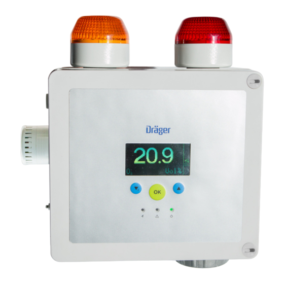
DC or AC power supply. Gas concentrations, status messages, and menu choices are displayed on a backlit graphic LC-display and 3 colored LEDs. The backlight color can be switched to red or green. Instructions for use Dräger PointGard 2000 Series... -
Page 10: Pointgard 2700 Ir Remote
ICES-003 class B. ► Disconnect power from the instrument and wait at least 1 CAN ICES-3 (B)/NMB-3 (B) minute before continuing. 1. Loosen the screws and open the cover. Instructions for use Dräger PointGard 2000 Series... -
Page 11: Power Supply Connector And Wiring Tables
► Using AC loads, make sure that relay contacts are only 5. Secure the cable cores by tightening a cable tie around connected to devices sharing a common phase. them. 6. Plug the power supply connector into the appropriate power supply socket. Instructions for use Dräger PointGard 2000 Series... -
Page 12: 4-20Ma Interface
Only an operation as current source is possible. 3. Close the instrument. 3-pin connector A 3-pin connector is provided for the connection of the 4-20 mA interface wiring. Instructions for use Dräger PointGard 2000 Series... -
Page 13: Installation Of Sensors
The instrument starts the warm-up phase. The display shows that the sensor is ready for For the current of the analog interface corresponding to the measurement in hh:mm:ss (countdown). analog signal, see 17.2. Instructions for use Dräger PointGard 2000 Series... -
Page 14: Ending Special States
Fault / warning indication condition clears, the red LED is lit continuously to indicate Faults and warnings are non-latching. If the fault or warning the present alarm condition. condition clears, the message disappears. Instructions for use Dräger PointGard 2000 Series... -
Page 15: Definitions Of Indicators In The Display
Enter Settings PWD The Info mode is used to show instrument relevant information. This does not interrupt the normal operation of the instrument. ● Tap and hold for 3 seconds in measuring mode. Instructions for use Dräger PointGard 2000 Series... -
Page 16: Displaying Information
1) Observe sensor data sheet and sensor IfU should be established. The plant operator should establish 2) For applications in line with EN45544-1 the calibration interval must customized calibration intervals with the obtained data. not exceed 6 months. Instructions for use Dräger PointGard 2000 Series... -
Page 17: Gas Flow For Calibrations
1. Select Calibration > Zero calibration and confirm. The Maintenance signal is transmitted by the analog interface, no alarm or fault relays are switched and the symbol is displayed. The message Apply zero gas is displayed. Instructions for use Dräger PointGard 2000 Series... -
Page 18: Span Calibration
1) Not applicable for all sensors (see "Display, analog interface and relay status", page 13). 2) For LC sensors the test gas must be applied for at least 6 minutes. Instructions for use Dräger PointGard 2000 Series... -
Page 19: Changing The Fuse
Battery for data Have the instrument has been con- memory empty. checked by DrägerService. nected. Instrument fault. Have the instrument checked by DrägerService. Instructions for use Dräger PointGard 2000 Series... -
Page 20: Maintenance
10.1 Performing a bump test configuration. This can be prohibited if the sensor lock function 26 is activated. A bump test checks alarm activation without setting off the alarms. Instructions for use Dräger PointGard 2000 Series... -
Page 21: Pointgard 2200 Cat
7. Plug the sensor connector to the socket. 1. Select Settings > Instrument > Language and confirm. 8. Close the instrument. 2. Select a language from the list and confirm 9. Commission the instrument. Instructions for use Dräger PointGard 2000 Series... -
Page 22: Configuring Function Key
11.7 Relays The measured value and the symbol are displayed. With factory default settings and during normal operation, the relays are energized. This provides a “fail-safe” operation. The fault relay indicates a fault. Instructions for use Dräger PointGard 2000 Series... -
Page 23: Configuring Alarms
✓ The new settings are saved. 11.11.3 Changing the display mode 1. Select Settings > Instrument > Display > Display mode and confirm. 2. Select the desired mode and confirm. Standard Shows the standard display. Instructions for use Dräger PointGard 2000 Series... -
Page 24: Configuration Of Integrated Alarm Devices
13.1.4 Switching the warning signal on or off to the right 1. Select Settings > Communication > Analog interface > 3. Close the instrument. Warning and confirm. 4. Commission the instrument. 2. Select Enable or Disable and confirm. Instructions for use Dräger PointGard 2000 Series... -
Page 25: Setting Warning Interval
Inhibit all alarms. 3. Set the current and confirm. 3. Select Enable or Disable and confirm. The setting for the Analog span is displayed. 4. Select Confirm and confirm with [OK]. Instructions for use Dräger PointGard 2000 Series... -
Page 26: Beam Block
Measurement fluctuations are minor variations in measured 1. Select Settings >Sensor > Sensor lock and confirm. values (such as signal noise, variations in concentration). Those variations do not change the transmitted or displayed 2. Select On or Off. Instructions for use Dräger PointGard 2000 Series... -
Page 27: Software Dongles For Ec Sensors
This setting does not apply for LC sensors. The current full scale deflection is displayed. 1. Select Settings > Sensor > DQ Sensor latch. and confirm. The current setting is displayed. Instructions for use Dräger PointGard 2000 Series... -
Page 28: Sensor Settings Pointgard 27X0 Ir
15.1.1 PointGard 2xx0 15.2.1 PointGard 2100 EC Menu Default setting Range Menu Default setting Range Relay active on Active on alarm On / Off alarm / No alarm A1 Alarm Depending on the sensor Instructions for use Dräger PointGard 2000 Series... -
Page 29: Pointgard 2200 Cat Drägersensor ® Dq
Hysteresis for A1 0.1 % LEL 0 to A1 trations alarm at direction A1 Alarm 20 %LEL 0.01 to 100 Vol% at unit rising %LEL = 0.3 to 100 %LEL A2 Alarm 40 %LEL Instructions for use Dräger PointGard 2000 Series... -
Page 30: Pointgard 2720 Ir
On / Off LEL type NIOSH IEC / PTB / NIOSH / configu- Beam block 2 mA 0 to 3.5 mA rable current Measured Propane Beam block 0.1 Vol% 0 to 0.1 Vol% limit Instructions for use Dräger PointGard 2000 Series... -
Page 31: Disposal
0 to 5 Vol%, 2700 For CH4 (Methane) 0 to 100 Cable specification 3 x 0.75 mm² / 3 x AWG 19/7 Vol% Ferrules 0.75 mm² / AWG 19/7 8 mm / 0.3 in insulated Instructions for use Dräger PointGard 2000 Series... -
Page 32: Dc Version
4, braided screen on both Temperature (storage) -20 ... +65°C / -4 ... +149°F sides Temperature (operation) -20 ... +50°C / -4... +122°F Cover ≥ 80 % Relative Humidity (operation) 0 … 95 % (non-condensing) Instructions for use Dräger PointGard 2000 Series... -
Page 33: Sensor Range And Default Alarm Values
Mounting brackets 8326497 Hydride 6809980 18.1.2 Spare parts 6809650 Part Part number HCN LC 6813200 Cable gland (M20 x 1.5) 8314595 6809655 Cable gland (1.5’’) 8326479 LC 6813205 O-ring 8326457 6809660 Counter-nut 1390139 6809665 Instructions for use Dräger PointGard 2000 Series... -
Page 34: Power Supply Cables
(Ex d explosion proof) Dräger PIR 7200 (NPT) 6811572 Junction Box Stainless Steel 4544098 Dräger PIR 7200 (M25) 6812290 (Ex d explosion proof) HART, complete set DrägerSensor PR NPT DQ 6814150 Instructions for use Dräger PointGard 2000 Series... - Page 35 Inhaltsverzeichnis Inhaltsverzeichnis Dräger PointGard 2000 Series Sicherheitsbezogene Informationen ....7.5.3 Funktionstaste verwenden ........Menü ..............Sicherheitshinweise ..........7.6.1 Navigation im Menü ..........Einsatzbereich und Einsatzbedingungen ..... 7.6.2 Kennwörter ............1.2.1 PointGard 2xx0 Remote........7.6.3 Zugriff auf Menüs ..........Mechanische Installation........
-
Page 36: 18.4 Pointgard 27X0 Ir
15.2.5 PointGard 2700 IR ..........15.2.6 PointGard 2720 IR ..........Entsorgung............Technische Daten ..........17.1 Messbereiche ............17.2 Signalübertragung zur Auswerteeinheit....17.3 Spannungsversorgung ........17.3.1 AC-Version ............17.3.2 DC-Version ............17.4 Physische Spezifikationen ........17.5 Umgebungsparameter ......... Gebrauchsanweisung Dräger PointGard 2000 Series... -
Page 37: Sicherheitsbezogene Informationen
Gerät gehörig – Bei Instandsetzung an diesen Geräten oder Bauteilen gekennzeichnet sein. müssen die entsprechenden Bestimmungen beachtet werden. – Es müssen Aderendhülsen verwendet werden. – Die Kabelisolierung muss auf 5 bis 7 mm entfernt werden. Gebrauchsanweisung Dräger PointGard 2000 Series... -
Page 38: Inbetriebnahme
Dieses Dreieck kennzeichnet in Warnhinweisen mit Ersatzgas justiert werden. die Möglichkeiten zur Vermeidung der Gefähr- dung. > Das Größer-als-Zeichen gibt einen Navigations- pfad in einem Menü an. Dieses Symbol kennzeichnet Informationen, die die Verwendung des Produkts erleichtern. Gebrauchsanweisung Dräger PointGard 2000 Series... -
Page 39: Marken
PointGard 2100 EC einem Abtastintervall von 1 Messung pro Minute speichert der Bajonettring Datenlogger den Messverlauf von ca. 24 Tagen. Diese Zeit kann durch die Aktivierung der Trigger-Funktion deutlich Einstellschraube (2-mm-Innensechskant- verlängert werden. schraube) Anschluss für EC-Sensor Gebrauchsanweisung Dräger PointGard 2000 Series... -
Page 40: Pointgard 2200 Cat Remote
Das Gerät ist nicht für den Betrieb in Bereichen mit Drehmoment angezogen (4.4 ... 5.3 Lbs. In./0.5 ... 0.6 explosionsfähiger Atmosphäre ausgelegt. Nm). ► Nicht in explosionsfähiger Atmosphäre verwenden. b. Alle Kabelsteckverbinder sind mit Schrauben befestigt. Gebrauchsanweisung Dräger PointGard 2000 Series... -
Page 41: Steckverbinder Für Spannungsversorgung Und Verdrahtungstabellen
4. Schrauben des Steckverbinders mit dem richtigen Für die Verdrahtung des Relais wird ein 9-poliger Drehmoment (4.4 ... 5.3 Lbs. In./0.5 ... 0.6 Nm) festziehen. Steckverbinder mitgeliefert. 5. Einen Kabelbinder um die Kabeladern befestigen, um diese zu sichern. Gebrauchsanweisung Dräger PointGard 2000 Series... -
Page 42: 4-20-Ma-Schnittstelle
5. Den Steckverbinder in die Buchse stecken und die Schrauben mit dem richtigen Drehmoment (1.9 ... 2.2 Lbs. Stö- Arbeitskontakt (Normally In./0.22 ... 0.25 Nm) festziehen. rung Open) 6. Gerät schließen. Anschluss des 9-poligen Steckverbinders 1. Die Relaisdrähte durch die vorgesehene Kabelverschraubung verlegen. Gebrauchsanweisung Dräger PointGard 2000 Series... -
Page 43: Software-Dongles Installieren
Messköpfen Abhängig von der Explosionsschutzart werden Anzeige, Analogschnittstelle und unterschiedliche Messköpfe verwendet. Informationen zur Relaisstatus Montage der unterschiedlichen Sensorköpfe sind der Gebrauchsanweisung des entsprechenden Messkopfes zu Die folgenden Beispielanzeigen stammen von PointGard entnehmen. 2100 EC. Gebrauchsanweisung Dräger PointGard 2000 Series... -
Page 44: Messbetrieb
Wert über-/unterschreitet den Messbereich das Symbol angezeigt. Die Anzeige gibt an, dass die Gaskonzentration außerhalb Analogschnittstelle: Fehlerstrom des Messbereichs des Sensors ist. Die Anzeige erlischt, Relais: Fehlerrelais-Schalter sobald die Gaskonzentration wieder innerhalb des Messbereiches ist. Gebrauchsanweisung Dräger PointGard 2000 Series... -
Page 45: Leds Und Symbolanzeigen
– Wenn der zweite Alarm (Hauptalarm) ausgelöst wurde, Je nach Art des Menüs verschiedene Funktionen blinkt die rote LED zweifach – Wenn ein Alarm quittiert wurde, bevor die Alarmbedingung aufgelöst ist, ist die rote LED dauerhaft beleuchtet, um eine aktuelle Alarmbedingung anzuzeigen. Gebrauchsanweisung Dräger PointGard 2000 Series... -
Page 46: Info-Modus Und Funktionstaste
7.6.3 Zugriff auf Menüs 1) Die Funktion ist nur mit dem Diagnosedongle verfügbar. ● Um das Menü Information direkt zu öffnen: a. Im Messmodus 1 Sekunde lang gedrückt halten. ● Um das Menü Kalibrierung zu öffnen: Gebrauchsanweisung Dräger PointGard 2000 Series... -
Page 47: Justierung
Dies gilt nicht für die Anbringung an Lüftungskanälen oder 1) Sensor-Datenblatt und Sensor-Gebrauchsanweisung beachten wenn die Prozessadapternummer verwendet wird (siehe 2) Für Anwendungen gemäß EN45544-1 darf der Justierintervall 6 Installationsanweisung für PIR 7x00-Zubehör). Monate nicht überschreiten. Gebrauchsanweisung Dräger PointGard 2000 Series... -
Page 48: Gasdurchfluss Für Justierungen
6. Den Gasdurchfluss abstellen und den Justieradapter vom den Sensor gelangt. Sensor entfernen oder den Schlauch lösen. Liegt der aktuelle Wert außerhalb des Alarmbereichs: 7. weiter wählen und bestätigen. Das Gerät schaltet in das Justierungsmenü zurück. Gebrauchsanweisung Dräger PointGard 2000 Series... -
Page 49: Empfindlichkeitsjustierung
Messeinheit aus der Liste wählen und bestätigen. 5. Gerät in Betrieb nehmen. 1) Nicht für alle Sensoren zutreffend (siehe „Anzeige, Analogschnittstelle 2) Bei LC-Sensoren muss das Prüfgas mindestens 6 Minuten lang auf- und Relaisstatus“, Seite 43). gegeben werden. Gebrauchsanweisung Dräger PointGard 2000 Series... -
Page 50: Fehler
überprüfen lassen. PointGard 27x0 IR-spezifisch leer. Fehler- Ursache Abhilfe 110, 111, Der SW-Dongle SW-Dongle deaktivieren. nummer wurde ohne Deakti- vierung entfernt. 064, 071 Kommunikations- Anschluss an PIR 7x00 fehler. prüfen. Alarme sind Alarme aktivieren. gesperrt. Gebrauchsanweisung Dräger PointGard 2000 Series... -
Page 51: Instandhaltung
► Nach Austauschen des Sensors, müssen sämtliche Einstellungen und Parameter auf Richtigkeit überprüft werden. 10.1 Begasungstest durchführen ► Justierung überprüfen, um korrekten Betrieb sicherzustellen. Ein Begasungstest (Bump Test) prüft die Alarmgebung, ohne den Alarm auszulösen. Gebrauchsanweisung Dräger PointGard 2000 Series... -
Page 52: Pointgard 2100 Ec
Weitere Informationen und Konfigurationen finden Sie im ist. technischen Handbuch 9300148. 4. Kalibrierung prüfen. Falls erforderlich, das Gerät justieren (siehe „Justierung“, Seite 47). 11.1 Kennwörter einstellen 1. Unter Einstellungen > Instrument > Kennwörter > das gewünschte Kennwort wählen und bestätigen. Gebrauchsanweisung Dräger PointGard 2000 Series... -
Page 53: Datum Und Uhrzeit Einstellen
Relaisausgang darzustellen. 1. Einstellungen > Instrument > Geräteinit wählen und 1. Unter Einstellungen > Instrument > Alarm > Fehler bestätigen. beim Einlaufen die gewünschte Option wählen und bestätigen. 2. Bestätigen wählen und mit [OK] bestätigen. Gebrauchsanweisung Dräger PointGard 2000 Series... -
Page 54: Alarmkonfiguration
Alarmbedingung wählen und bestätigen. Steigend Die Alarmrichtung ist steigend, wenn die Gaskonzentration einen bestimmten Wert Alarm A1 set- Simuliert einen Voralarm überschreiten muss, damit ein Alarm akti- viert wird. Alarm A2 set- Simuliert einen Hauptalarm Gebrauchsanweisung Dräger PointGard 2000 Series... -
Page 55: Dongles Deaktivieren
2. Schiebehebel des DIP-Schalters umlegen: nach links Wenn ein Alarm ausgelöst wird, wird auf dem Display die aktuelle Gaskonzentration angezeigt und die rote LED blinkt, nach rechts unabhängig vom ausgewählten Anzeigemodus. 3. Gerät schließen. Gebrauchsanweisung Dräger PointGard 2000 Series... -
Page 56: Schnittstelleneinstellungen
2. Strom festlegen und bestätigen. 13.1.9 Analogen Offset einstellen Diese Funktion fügt dem analogen Ausgang bei 4 mA ein Offset hinzu. Das Offset passt den Strom bei 4 mA an, ohne den 20 mA-Sollwert zu beeinflussen. Gebrauchsanweisung Dräger PointGard 2000 Series... -
Page 57: Analogempfindlichkeit Einstellen
● Um das Beam Block-Signal zu aktivieren/deaktivieren: 6. Gewünschte Option auswählen: 1. Unter Einstellungen > Kommunikation > 4-20mA- Schnittst > die gewünschte Option auswählen. Beam Bl. ein/aus Mithilfe dieser Funktion lässt sich der Beam Block ein- bzw. ausschalten Gebrauchsanweisung Dräger PointGard 2000 Series... -
Page 58: Sensoreinstellungen Pointgard 2Xx0
Einstel- des Bereichs, in welchem der Fangwert angezeigt wird. lungen durch die Standardeinstellungen des Untere Fangbereichsgrenze neuen Sensors überschrieben. Die untere Fangbereichsgrenze bestimmt den niedrigsten Wert des Bereichs, in welchem der Fangwert angezeigt wird. Gebrauchsanweisung Dräger PointGard 2000 Series... -
Page 59: Software-Dongle Für Ec-Sensoren
[OK] bestäti- gen. 3. Messeinheit aus der Liste wählen und bestätigen. Der aktuelle Messbereichsendwert wird angezeigt. 4. Nur für bestimmte EC-Sensoren: Messbereichsendwert einstellen und bestätigen. Der neue Messbereichsendwert wird angezeigt. Gebrauchsanweisung Dräger PointGard 2000 Series... -
Page 60: Einstellen Der Dq-Sensorverriegelung
1,2 mA 0 bis 3,5 mA um die Funktion ohne Ände- rung zu verlassen und mit Warnung Ein/Aus [OK] bestätigen. Warnstrom 3,0 mA 0 bis 3,5 mA Warnzyklusinter- 10 Sek. 5 bis 60 Sek. vall T1 Gebrauchsanweisung Dräger PointGard 2000 Series... -
Page 61: Sensorspezifische Werte
Hysterese für A1- 1 %UEG 0 bis A1 Alarm bei steigen- Alarm bei steigen- der Richtung der Richtung Justierintervall 0 bis 360 Hysterese für A2- 1 %UEG 0 bis A2 [Tage] Alarm bei steigen- der Richtung Gebrauchsanweisung Dräger PointGard 2000 Series... -
Page 62: Pointgard 2700 Ir
Beam Block- 2 mA 0 bis 3,5 mA Ansprech? normal normal / schnell Strom verhalten Beam Block- 2,5 %UEG 0 bis max. 15 %UEG Grenze Kal.-Intervall 0 bis 720 [Tage] Ansprechver- normal normal / schnell halten Gebrauchsanweisung Dräger PointGard 2000 Series... -
Page 63: Pointgard 2720 Ir
Displayerfas- -200 ppm -1000 bis 1000 ppm sung niedrig (Kohlenstoffdioxid) 17.2 Signalübertragung zur Displayerfas- 200 ppm Auswerteeinheit sung hoch Messbereich und messtechnische Eigenschaften hängen vom installierten Sensor ab (siehe Gebrauchsanweisung und/oder Datenblatt der installierten Sensoren). Gebrauchsanweisung Dräger PointGard 2000 Series... -
Page 64: Spannungsversorgung
20,7 ... 38,4 inHg (AC) , 50 Hz Min. 0.1 A - Verschmutzungsgrad 5 A bei 30 V (DC) Sicherung 5x20 mm T 0,5 A L 250 V ¼“ x 1¼“ T 0,5 A L 250 V Gebrauchsanweisung Dräger PointGard 2000 Series... -
Page 65: Anzugsdrehmoment Für Gerätegewinde
6809980 Kabel müssen für die vorgesehene Umgebungstemperatur ausgelegt sein. Die Schirmung muss auf beiden Seiten fest verdrahtet sein. 6809650 HCN LC 6813200 Adern 4, Schirmgeflecht auf beiden Seiten 6809655 Abdeckung ≥ 80 % LC 6813205 Gebrauchsanweisung Dräger PointGard 2000 Series... -
Page 66: Zubehör Und Ersatzteile
18.1.1 Zubehör für PointGard 2xx0 kopf Remote Remote-Kabel + Stecker 8323305 Teil Sachnummer (5 m) Spritzschutz 6812510 Remote-Kabel + Stecker 8323315 Justieradapter V 6810536 (15m) Begasungsadapter 6806978 Remote-Kabel + Stecker 8323330 (30m) Aufhängung 8326497 Sensordiagnosedongle 8317860 Sensortestdongle 8317619 Gebrauchsanweisung Dräger PointGard 2000 Series... -
Page 67: Pointgard 2200 Cat
Überprüfen Sie die Firmware-Kompatibilität von Sensor und Sender. Der Wechsel des Sensors erfordert möglicherweise eine Firmware-Aktualisierung. Für Unterstützung wenden Sie sich an Dräger. Beschreibung Sachnummer Dräger PIR 7000 Typ 334 6811822 (NPT) Dräger PIR 7000 Typ 340 6811832 (NPT) Gebrauchsanweisung Dräger PointGard 2000 Series... - Page 68 Sommaire Sommaire Dräger PointGard 2000 Series Mode Info et touche de fonction ......Informations relatives à la sécurité....7.5.1 Activer le mode Info ..........Consignes de sécurité ......... 7.5.2 Navigation en mode Info ........Zone et conditions d'utilisation......7.5.3 Utiliser la touche de fonction........
- Page 69 15.2.4 PointGard 2200 CAT Remote DSIR ....15.2.5 PointGard 2700 IR ..........15.2.6 PointGard 2720 IR ..........Elimination ............Caractéristiques techniques ......17.1 Plages de mesure ..........17.2 Transmission du signal vers l'unité de commande Notice d'utilisation Dräger PointGard 2000 Series...
-
Page 70: Informations Relatives À La Sécurité
– Le disjoncteur ou le fusible doit être facilement accessible composants. et marqué comme correspondant à l'instrument. – Les embouts doivent être utilisés. – L'isolation du câble doit être dénudée de 5 à 7 mm. Notice d'utilisation Dräger PointGard 2000 Series... -
Page 71: Mise En Service
> Le symbole « supérieur à » indique un chemin de navigation dans un menu. Ce symbole signale des informations qui facilitent l’utilisation du produit. Notice d'utilisation Dräger PointGard 2000 Series... -
Page 72: Marques
Port pour capteur EC électrochimique (EC) installé. Le capteur EC doit être commandé et installé séparément. Un boîtier pour capteur EC Fiche pour capteur EC à distance Notice d'utilisation Dräger PointGard 2000 Series... -
Page 73: Pointgard 2200 Cat
CAN ICES-3 (B)/NMB-3 (B) Risque d'explosion L'instrument en tant que tel n'est pas destiné à une utilisation dans des zones dangereuses avec des atmosphères à risque d'explosion. ► Ne pas utiliser dans les atmosphères à risque d'explosion. Notice d'utilisation Dräger PointGard 2000 Series... -
Page 74: Montage Et Installation
2. Veuillez vous assurer que les connexions suivantes sont Si un câble non blindé est utilisé ou si la protection de correctement effectuées : mise à la terre n'est pas connectée, nous vous invitons à ponter les broches 1 et 2. Notice d'utilisation Dräger PointGard 2000 Series... -
Page 75: Montage De L'instrument
4.5.2 Raccords de relais ment Les raccords de relais autorisent l'activation des dispositifs Dys- Normalement ouvert d'alarme externes. fonc- tionne Connecteur à 9 broches ment Un connecteur à 9 broches est fourni pour le câblage des relais. Notice d'utilisation Dräger PointGard 2000 Series... -
Page 76: Interface 4-20 Ma
5. Veuillez brancher le connecteur dans la prise et serrer les vis au couple de serrage prescrit (1.9 ... 2.2 Lbs. In. / 0.22 ... 0.25 Nm). 6. Fermer l'instrument. Notice d'utilisation Dräger PointGard 2000 Series... -
Page 77: Mise En Service De L'appareil
La concentration de gaz se situe hors veuillez vous reporter au manuel de la série Polytron 8000 de la plage de mesure du capteur. (9033848). Vol.% Interface analogique : Dérive en dessous de zéro Relais : Relais de défaut commute Notice d'utilisation Dräger PointGard 2000 Series... -
Page 78: Terminer Les Status Spéciaux
(Voir – Lorsque la deuxième alarme (alarme principale) a été "Affichage d’informations", page 80) et démarrer le déclenchée, la LED rouge clignote en mode double dépannage (Voir "Dépannage", page 83). Notice d'utilisation Dräger PointGard 2000 Series... -
Page 79: Définitions Des Indicateurs Affichés À L'écran
Par défaut : _ _ _ 2 Touche vers le bas / menu Différentes fonctions selon le type de menu Pour modifier les mots de passe, voir 11.1. 7.6.3 Accéder au menu ● Pour accéder directement au menu Information : Notice d'utilisation Dräger PointGard 2000 Series... -
Page 80: Affichage D'informations
1) Observer la fiche technique du capteur et la notice d'utilisation du cap- Mémoire teur 2) Pour les applications conformes à la norme EN45544-1, l’intervalle de calibrage ne doit pas être supérieur à 6 mois. Notice d'utilisation Dräger PointGard 2000 Series... -
Page 81: Préparation Au Calibrage
1. Raccorder le régulateur de pression au cylindre de gaz de ► S'assurer que le débit de l'air ambiant au niveau du calibrage. capteur est suffisant. 2. Fixer un adaptateur de calibrage sur la protection anti- éclaboussures jusqu'à ce qu'il s'enclenche. Notice d'utilisation Dräger PointGard 2000 Series... -
Page 82: Effectuer Le Réglage Du Point Zéro
Sélectionner l'unité de mesure de votre choix dans la 7. Sélectionner Suite et confirmer. liste et valider. L'instrument retourne au menu calibrage. 1) Ne s’applique pas à tous les capteurs (Voir "Affichage, interface ana- logique et état du relais", page 77). Notice d'utilisation Dräger PointGard 2000 Series... -
Page 83: Calibrage Automatique
5. Mettre l'appareil en service. 7x00 sale. propre. Plage de tension Contrôler la tension d'ali- d'alimentation mentation. extérieure 1) Pour les capteurs LC, le gaz étalon doit être appliqué pendant au mois 6 minutes. Notice d'utilisation Dräger PointGard 2000 Series... -
Page 84: Rapport D'info
Ne les déclencher. n’est pas encore pas procéder au calibrage terminée. Il faut avant que le capteur se soit s'attendre à une complètement stabilisé. erreur de mesure plus importante. Notice d'utilisation Dräger PointGard 2000 Series... -
Page 85: Contrôle Du Temps De Réponse (T90)
► Vérifier le calibrage pour garantir un fonctionnement invitons à calibrer l'instrument (Voir "Calibrage", page 80). correct. 10.3.2 PointGard 2200 CAT Remplacement du capteur Ce point ne s'applique qu'au PointGard 2200 CAT hors système à distance. Notice d'utilisation Dräger PointGard 2000 Series... -
Page 86: Pointgard 2700 Ir Remote
2. Sélectionner Confirmer et valider avec [OK]. Code Mainten. Accès au calibrage du point zéro et de la sensibilité Code Config. Accès à tous les paramètres de configura- tion Notice d'utilisation Dräger PointGard 2000 Series... -
Page 87: Associations D'auto-Maintien Et D'acquittement D'alarme
Cette fonction est utilisée pour régler le fonctionnement du tée, si la concentration du gaz a dépassé relais de défaut pendant la stabilisation 1 afin d'indiquer l'état une certaine valeur pour activer une de stabilisation 1 à la sortie du relais. alarme. Notice d'utilisation Dräger PointGard 2000 Series... -
Page 88: Test Des Alarmes / Relais
Alarme A1 simule la pré-alarme d'alarme intégrés Alarme A2 simule l'alarme principale Pour plus d'informations et de configurations, nous vous test. Erreur simule le signal de défaut invitons à consulter le manuel technique 9300148. Notice d'utilisation Dräger PointGard 2000 Series... -
Page 89: Commutateur Dip
Interface analog > Rapport d’ Info et confirmer. La sortie électrique de l'instrument en mode normal de 2. Sélectionner Activée ou Désactivée et confirmer. fonctionnement est comprise entre 4 et 20 mA et est proportionnelle à la concentration de gaz détectée. Notice d'utilisation Dräger PointGard 2000 Series... -
Page 90: Réglage De L'intervalle D'avertissement
2. Sélectionner la ligne correspondant à la modification de la l'intensité par défaut. correction (plage: -0,5 à 0,5 mA) et confirmer. Régl. alarme Règle l'intensité électrique à 3. Régler et valider le courant. l'intensité d'avertissement. Le réglage pour Sensibilité analogique est affiché. Notice d'utilisation Dräger PointGard 2000 Series... -
Page 91: Beam Block
1. Sélectionner Configuration > Capteurs > Init basic Réglages capteur PointGard 2xx0 Canal et confirmer. 2. Sélectionner Confirmer et valider avec [OK]. 14.1 Activation ou désactivation du calibrage automatique 1. Sélectionner Configuration > Capteurs > Autocalibrage et confirmer. Notice d'utilisation Dräger PointGard 2000 Series... -
Page 92: Configuration Période De Calibrage
1. Sélectionner Configuration > Capteurs > Régl. test capteur et confirmer. 1. Sélectionner Configuration > Capteurs > Gas-Cfg et valider. 2. Sélectionner Activée ou Désactivée et confirmer. Test capteur manuel Cette fonction permet la déclenchement manuel d'un test capteur. Notice d'utilisation Dräger PointGard 2000 Series... -
Page 93: Réglage Du Verrouillage Du Capteur Dq
Non acquittable 1. Sélectionner Configuration > Capteurs > Gas-Cfg et ment A2 confirmer. Le gaz actuellement mesuré s'affiche. 2. Sélectionner le gaz cible dans la liste et valider. L'unité de mesure actuelle s'affiche. Notice d'utilisation Dräger PointGard 2000 Series... -
Page 94: Valeurs Spécifiques Du Capteur
Voir la fiche technique du capteur pour plus de spécifications. Dépassement 100 % LIE La plage n’est pas 15.2.1 PointGard 2100 EC d’échelle ajustable Menu Réglage par Plage défaut Alarme A1 Suivant le capteur utilisé Notice d'utilisation Dräger PointGard 2000 Series... -
Page 95: Pointgard 2200 Cat Drägersensor ® Lc
0 à 4 % LIE chage élevée 1) La limite max. du beam block dépend du type de transmetteur et du gaz de mesure sélectionné. Dépassement 100 % LIE La plage n’est pas d'échelle ajustable Notice d'utilisation Dräger PointGard 2000 Series... -
Page 96: Pointgard 2720 Ir
15.2.6 PointGard 2720 IR brûlures à l'acide. ► Ne pas jeter les capteurs au feu Menu Réglage par Plage ► Ne pas ouvrir en forçant défaut Gaz de calibrage Unités de gaz Vol % de calibrage Notice d'utilisation Dräger PointGard 2000 Series... -
Page 97: Caractéristiques Techniques
Puissance nominale du 12 W à 24 V (CC), 25 °C ment. PointGard 2700 Dysfonctionnement > 21 mA Spécification du câble 2 x 1,5 mm² / 2 x AWG 16/7 sur la sortie analo- gique Notice d'utilisation Dräger PointGard 2000 Series... -
Page 98: Spécifications Physiques
Dräger PIR 7000 / PIR 7200 correspondant. Pièce Couple Lbs. In. Couple Nm Presse-étoupe 13 +/- 4,4 1,5 +/- 0,5 (M20 x 1,5) Presse-étoupe contre écrou (1,5’’) Bouchon à vis 4,4 ... 5,3 0,5 ... 0,6 Notice d'utilisation Dräger PointGard 2000 Series... -
Page 99: Portée Du Capteur Et Valeurs D'alarme Par Défaut
Joint torique 8326457 6809705 Contre-écrou 1390139 6809675 1000 4000 7000 200 2800 Bouchon à vis 8326456 Kit de pièces détachées, rac- 8326496 6809685 1000 3000 200 cord de capteur CatEx à dis- tance COCI2 6809930 Notice d'utilisation Dräger PointGard 2000 Series... -
Page 100: Câbles D'alimentation
Kit complet (Ex d antidéflagrant) Dräger PIR 7200 (NPT) 6811572 Boîte de connexion en acier 4544098 inoxydable Dräger PIR 7200 (M25) 6812290 (Ex d antidéflagrant) HART, kit complet DrägerSensor PR NPT DQ 6814150 Notice d'utilisation Dräger PointGard 2000 Series... - Page 101 Contenido Contenido Dräger PointGard 2000 Series Información relativa a la seguridad ....103 7.5.3 Uso de la tecla de función........111 Menú ..............112 Indicaciones de seguridad ........103 7.6.1 Navegación por menús ........112 Área de operación y condiciones de operación ... 103 7.6.2...
- Page 102 15.2.5 PointGard 2700 IR ..........128 15.2.6 PointGard 2720 IR ..........129 Eliminación............129 Características técnicas........129 17.1 Rangos de medición ..........129 17.2 Transmisión de señal al controlador....130 17.3 Alimentación eléctrica.......... 130 Instrucciones de uso Dräger PointGard 2000 Series...
-
Page 103: Información Relativa A La Seguridad
– Se deben utilizar virolas. – El aislamiento del cable se debe pelar entre 5 y 7 mm. Instrucciones de uso Dräger PointGard 2000 Series... -
Page 104: Puesta En Funcionamiento
– Los gases metano e hidrógeno sólo se deberían calibrar > El signo mayor que indica una ruta de navegación con gas objetivo y no con un gas sustituto. en un menú. Este símbolo indica información que facilita el uso del producto. Instrucciones de uso Dräger PointGard 2000 Series... -
Page 105: Marcas Comerciales
El instrumento monitoriza las concentraciones de gases tóxicos o el oxígeno en el aire ambiental, según el sensor Enchufe del sensor remoto EC electroquímico (EC) instalado. El sensor EC hay que pedirlo e Instrucciones de uso Dräger PointGard 2000 Series... -
Page 106: Pointgard 2200 Cat
Los tornillos de cableado están apretados con el par correcto (4.4 ... 5.3 Lbs. In./0.5 ... 0.6 Nm). b. Todos los conectores de cables se fijan con tornillos. c. El conector del sensor está enchufado (solo PointGard 2200 CAT). Instrucciones de uso Dräger PointGard 2000 Series... -
Page 107: Conector De Alimentación Y Tablas De Conexiones
7. Apretar los tornillos con el par correcto (4.4 ... 5.3 Lbs. con los que comparten una fase. In./0.5 ... 0.6 Nm). 8. Cerrar el instrumento. Instrucciones de uso Dräger PointGard 2000 Series... -
Page 108: Interfaz De 4-20 Ma
1. Abrir el instrumento. fuente de corriente. 2. Insertar la mochila con el logotipo de Dräger mirando hacia arriba en la ranura de la unidad PCB en la parte trasera de la cubierta. Instrucciones de uso Dräger PointGard 2000 Series... -
Page 109: Instalación De Sensores
PointGard 2200 CAT Remote Polytron SE (9033888) DSIR 7.1.2 Estados especiales PointGard 27x0 IR PIR 7x00 (9023885) Si el instrumento se encuentra en un estado especial, ya no se puede garantizar una alarma o medición correcta. Instrucciones de uso Dräger PointGard 2000 Series... -
Page 110: Finalización De Estados Especiales
1) Solo cuando la corriente de aviso está activada. Ajuste de fábrica: PointGard 2200 CAT remoto con sensor LC: desactivado. Fase de calentamiento 1 El símbolo aparece en el lado derecho de la pantalla. Instrucciones de uso Dräger PointGard 2000 Series... -
Page 111: Indicaciones De Símbolos Y Led
SIL está activado. El instrumento no tiene certificación SIL. Por tanto, no se permiten Para configurar la tecla de función, véase 11.4 Configuración las funciones SIL, aunque puede aparecer de la tecla de función. el símbolo. Instrucciones de uso Dräger PointGard 2000 Series... -
Page 112: Menú
Error Muestra mensajes de fallos en texto simple report y el número correspondiente. Si hay varios fallos, existirá un indicador (por ejemplo, 1/3 = pantalla 1 de 3). Instrucciones de uso Dräger PointGard 2000 Series... -
Page 113: Gases De Prueba
1) Véase la ficha de datos del sensor y las instrucciones de uso del sen- 2) Para aplicaciones de acuerdo con la norma EN45544-1, el intervalo de calibración no debe exceder los 6 meses. Instrucciones de uso Dräger PointGard 2000 Series... -
Page 114: Flujo De Gas Para Calibraciones
La calibración de sensibilidad se tiene que realizar antes de cero falla con una desviación de más de 0,6 vol% de O que transcurran 24 h desde la última calibración válida del punto cero. Instrucciones de uso Dräger PointGard 2000 Series... -
Page 115: Realización De Una Calibración De Sensibilidad
1) No aplicable a todos los sensores (consulte "Pantalla, interfaz analó- 2) En los sensores LC, el gas de prueba debe aplicarse durante al gica y estado del relé", página 109). menos 6 minutos. Instrucciones de uso Dräger PointGard 2000 Series... -
Page 116: Fallos
Específico para PointGard 27x0 IR: tware se ha elimi- software. Número Causa Solución nado sin ser de fallo desactivada. 064, 071 Fallo de comunica- Compruebe la conexión al Alarmas inhibidas. Habilitar alarmas ción. sensor PIR 7x00. Instrucciones de uso Dräger PointGard 2000 Series... -
Page 117: Mantenimiento
– Limpiar el instrumento con un paño suave y agua. No se central, (consulte "Comprobación de la interfaz debe utilizar detergente. analógica", página 123) ● Para comprobar los indicadores LED y la activación de dispositivos de alarma, (consulte "Comprobación de alarmas/relés", página 120) Instrucciones de uso Dräger PointGard 2000 Series... -
Page 118: Sustitución Del Sensor
Cuando el sensor nuevo está instalado, la pantalla muestra: “Cargando datos, por favor espere”. Ajustes del dispositivo Cuando los datos del sensor se han cargado, la pantalla muestra: “Datos cargados”. El manual técnico 9300148 contiene más información y configuraciones. Instrucciones de uso Dräger PointGard 2000 Series... -
Page 119: Ajuste De Contraseñas
Si se dispara una alarma, se excita el con- defecto Alarm tacto de relé. Esta función reinicia el instrumento a los ajustes por defecto de fábrica. 1. Seleccionar Ajustes > Instrumento > Inic.Instrumento y confirmar. Instrucciones de uso Dräger PointGard 2000 Series... -
Page 120: Ajuste Del Calentamiento 1 Del Relé De Fallo
LED volverá automáticamente a su estado a. Ajuste el valor del umbral de alarma. anterior. b. Ajuste la dirección de alarma. 1. Seleccionar Ajustes > Instrumento > Alarma la condición de alarma deseada y confirmar. Instrucciones de uso Dräger PointGard 2000 Series... -
Page 121: Desactivación De Mochilas
4. Poner en marcha el instrumento. los símbolos aplicables. Si se activa una alarma, la pantalla muestra la concentración de gas actual y el LED rojo parpadea sea cual sea el modo de pantalla seleccionado. Instrucciones de uso Dräger PointGard 2000 Series... -
Page 122: Ajustes De Interfaz
13.1.9 Ajuste de la desviación analógica Esta función añade una desviación a la salida analógica a 4 mA. La desviación ajusta la corriente a 4 mA sin afectar al valor de consigna de 20 mA. Instrucciones de uso Dräger PointGard 2000 Series... -
Page 123: Ajuste De La Sensibilidad Analógica
● Para ajustar las señales beam block: el valor de prueba actual. 1. Seleccione Ajustes > Comunicacion > Interf.analogico Durante la prueba, se mues- > y la opción deseada. tra el símbolo de manteni- miento . Instrucciones de uso Dräger PointGard 2000 Series... -
Page 124: Ajustes Del Sensor Pointgard 2Xx0
Sigue. 1. Seleccione Ajustes > Instrumento > SW conector y la 5. Comprobar todos los valores y confirmar con Sigue. mochila que se desea desactivar y confírmelo. Instrucciones de uso Dräger PointGard 2000 Series... -
Page 125: Ajustes Del Sensor Pointgard 2100 Ec
► Antes de confirmar un valor por encima del rango, Confirmar Seleccionar Confirmar para cerciórese de que la concentración de gas ha caído por aceptar los ajustes y confir- debajo de 100 %LIE. mar con [OK]. Instrucciones de uso Dräger PointGard 2000 Series... -
Page 126: Ajustes Del Sensor Pointgard 27X0 Ir
De -0,5 a 0,5 mA alarma/Sin alarma gica Alarma A1: direc- Ascendente (des- Descen- Sensibilidad ana- 0 mA De -0,5 a 0,5 mA ción cendente en sen- dente/Ascendente lógica sores de O Alarma A2: direc- Ascendente ción Instrucciones de uso Dräger PointGard 2000 Series... -
Page 127: Valores Específicos Del Sensor
-5 a 4 % LIE bración [días] captura de pantalla Desviación de 0 % LIE -3 a 4 % LIE Captura de panta- -5 % LIE -5 a 0 % LIE captura de pantalla lla, valor bajo Instrucciones de uso Dräger PointGard 2000 Series... -
Page 128: Pointgard 2700 Ir
2 mA Entre 0 y 3,5 mA beam block Límite beam- 2,5 % LIE 0 a máx. 15 % LIE block Intervalo cal. Entre 0 y 720 [días] Respuesta Normal Normal / Rápida Instrucciones de uso Dräger PointGard 2000 Series... -
Page 129: Pointgard 2720 Ir
Normal / Rápida sor de gas infrarrojo PIR 7000 Tipo 334 (IDS 01x1) 0 a 10.000 ppm 0 a 100 % LIE, 0 a 5 vol%, Para CH4 (metano) 0 a 100 vol% Instrucciones de uso Dräger PointGard 2000 Series... -
Page 130: Transmisión De Señal Al Controlador
6 W a 230 V (CA), 25 °C 17.5 Parámetros medioambientales PointGard 2100/2200 Potencia nominal de 12 W a 230 V (CA), 25 °C Para las especificaciones del sensor, véase la hoja de datos PointGard 2700 del sensor relevante. Instrucciones de uso Dräger PointGard 2000 Series... -
Page 131: Par De Apriete Para Roscas Del Instrumento
CO LS 6809620 1000 5000 200 prensaestopas S LC 6809610 Tamaño del cable 1 - 1,5 mm² (14-18 AWG) 6810435 Máx. 30 m/100 pies (sensor Longitud DD/DQ) S HC 6809710 1000 100 6810740 6810745 Instrucciones de uso Dräger PointGard 2000 Series... -
Page 132: Accesorios Y Piezas De Repuesto
IdU. Para información sobre otras piezas, consultar la lista de piezas de repuesto o contactar Componente Número de pieza con DrägerService. Kit de montaje de cabezal 6812684 detector remoto EC Instrucciones de uso Dräger PointGard 2000 Series... -
Page 133: Pointgard 2200 Cat
SE Ex HT M DQ 18.3.3 Sensores Designación Número de pieza DrägerSensor IR NPT 6811901 Cabezal detector del 6811165 juego completo e de Dräger- Sensor IR Cabezal detector del 6811265 juego completo e2 de Dräger- Sensor IR Instrucciones de uso Dräger PointGard 2000 Series... - Page 134 Содержание Содержание Dräger PointGard 2000 Series Информация по безопасности ...... 136 7.5.2 Навигация в информационном режиме ... 145 7.5.3 Использование функциональной кнопки..145 Инструкции по технике безопасности ....136 Меню ..............145 Область использования и условия....136 7.6.1 Работа с меню............ 145 1.2.1...
- Page 135 DQ.... 161 ® 15.2.3 PointGard 2200 CAT DrägerSensor LC..... 161 15.2.4 PointGard 2200 CAT Remote DSIR ....162 15.2.5 PointGard 2700 IR ..........162 15.2.6 PointGard 2720 IR ..........163 Утилизация ............163 Руководство по эксплуатации Dräger PointGard 2000 Series...
-
Page 136: Информация По Безопасности
проинформируйте Dräger. – Не допускается какая-либо модификация – Строго соблюдайте электрические нормативы, оборудования или компонентов. регулирующие прокладку и подключение электрических силовых и сигнальных кабелей к – Использование дефектных или некомплектных газосигнализационному оборудованию. деталей запрещено. Руководство по эксплуатации Dräger PointGard 2000 Series... -
Page 137: Ввод В Эксплуатацию
вание которой может приве- уровне моря (уменьшенное парциальное давление). сти к повреждению Если высота или давление окружающей среды оборудования или ущербу изменились, рекомендуется провести новую для окружающей среды. калибровку чувствительности. Заводская калибровка относится к уровню моря. Руководство по эксплуатации Dräger PointGard 2000 Series... -
Page 138: Типографские Обозначения
тока. Концентрация газа, сообщения о состоянии системы и пункты меню выводятся на подсвечиваемый ЖК Предохранитель для блока питания пере- дисплей и показываются тремя цветными светодиодными менного тока индикаторами. Цвет подсветки может переключаться на красный или зеленый. Руководство по эксплуатации Dräger PointGard 2000 Series... -
Page 139: Pointgard 2100 Ec
® коробка Polytron сигнальные устройства прибора (сирена и сигнальные ® – Сенсорные блоки Polytron SE Ex с типом лампы). Также могут быть подключены внешние взрывозащиты повышенная безопасность (Ex e). сигнальные устройства, которые включаются Руководство по эксплуатации Dräger PointGard 2000 Series... -
Page 140: Монтаж И Установка
Рекомендуемые параметры винтов: см. Защитное заземле- 18.1.4 Монтажные винты. ние Нейтральный про- Подключение интерфейсов вод 4.5.1 Подготовка к подключению Таблица подключения для версии постоянного тока интерфейсов Клемма Маркировка Функция 1. Откройте прибор. M / - Руководство по эксплуатации Dräger PointGard 2000 Series... -
Page 141: Соединения Реле
значения на контроллер. Возможна работа только в заземлению. режиме источника тока. Таблица подключения реле 3-контактный разъем Согласно заводским настройкам в нормальном режиме Для подключения интерфейса 4-20 мА предусмотрен 3- работы реле запитаны, что обеспечивает контактный разъем. “отказоустойчивую” работу. Руководство по эксплуатации Dräger PointGard 2000 Series... -
Page 142: Подключение Прибора К Контроллеру Dräger
2. Вставьте донгл эмблемой Dräger вверх в гнездо на PointGard 2200 CAT Сенсорные блоки Polytron печатной плате на обратной стороне крышки. PointGard 2200 CAT Remote SE Ex (9033888) DSIR 3. Закройте прибор. PointGard 27x0 IR PIR 7x00 (9023885) Руководство по эксплуатации Dräger PointGard 2000 Series... -
Page 143: Ввод В Действие Прибора
Это может произойти в следующих случаях: В правой части дисплея отображается символ – Если концентрация газа превышает диапазон Оставшееся время показано в левой части дисплея. измерения. Аналоговый интерфейс: Ток обслуживания – При возникновении неисправности. Руководство по эксплуатации Dräger PointGard 2000 Series... -
Page 144: Завершение Особых Состояний
должен поддерживать эту функцию! См. дополнительную информацию в: "Настройка самоблокировки сенсора DQ", Превышение измерительного диапазона стр. 159. аналогового интерфейса. PointGard 2200 CAT Remote с сенсором LC: Измеренное значение меньше диапа- зона аналогового интерфейса. Руководство по эксплуатации Dräger PointGard 2000 Series... -
Page 145: Относится К Pointgard 2100 Ec
Выберите Введите пароль c. Введите Уст. пароля конф. Кнопк Функция а 7.6.4 Отображение информации Переключает на следующий экран Выберите соответствующий пункт в меню Информация: Переключает на предыдущий экран Прибор Завершает информационный режим Руководство по эксплуатации Dräger PointGard 2000 Series... -
Page 146: Калибровка
межкалибровочных интервалов зависит от условий окружающей среды, в которых эксплуатируется сенсор. 1) Соблюдайте спецификацию и руководство по эксплуатации сен- сора 2) Для применения согласно EN45544-1 межкалибровочный интер- вал не должен превышать 6 месяцев. Руководство по эксплуатации Dräger PointGard 2000 Series... -
Page 147: Подготовка Калибровочной Установки
снимайте защиту от насекомых. проверки точки нуля возникло отклонение более чем 0,6 об% O от нуля, PointGard 2100 EC отобразит состояние 4. Подсоедините шланг к патрубку. 5. Войдите в меню, см. 7.6.3 Вход в меню Руководство по эксплуатации Dräger PointGard 2000 Series... -
Page 148: Калибровка Точки Нуля
Выберите единицу измерения из списка и Калибровка чувствительности подтвердите выбор. Относится к PointGard 2200 CAT / 2200 CAT Remote IR / 2700 IR: 1) Не применимо для всех сенсоров (см. "Дисплей, аналоговый интерфейс и состояние реле", стр. 143). Руководство по эксплуатации Dräger PointGard 2000 Series... -
Page 149: Автоматическая Калибровка
чите электропитание. При Параметры предохранителей: см. повторном появлении 17.3 Электропитание. неисправности: Обрати- 4. Закройте прибор. тесь в DrägerService для проверки прибора. 1) Для сенсоров LC тестовый газ должен подаваться не менее 6 минут. Руководство по эксплуатации Dräger PointGard 2000 Series... -
Page 150: Предупреждения
безопасности, с учетом условий эксплуатации действительны. прибора, и при необходимости сокращается. Неисправность Обратитесь в прибора. DrägerService для про- верки прибора. Разряжена бата- Обратитесь в реи для памяти DrägerService для про- данных. верки прибора. Руководство по эксплуатации Dräger PointGard 2000 Series... -
Page 151: Проведение Функциональной Проверки
Будет показан символ технического обслуживания. обслуживания, которое должно включать следующие 2. Замените старый сенсор на новый: задачи: a. Ослабьте стопорный винт. b. Снимите байонетное кольцо с корпуса. c. Снимите и утилизируйте накладку или старый сенсор, соответственно. Руководство по эксплуатации Dräger PointGard 2000 Series... -
Page 152: Pointgard 2200 Cat
1. При необходимости установите ток режима 2. Выберите функцию и подтвердите выбор. обслуживания для аналогового интерфейса. 2. Действуйте, как описано в руководстве сенсорного Показать Измерения за последние 15 минут пред- блока. график ставляются в виде графика концентра- ция/время. Руководство по эксплуатации Dräger PointGard 2000 Series... -
Page 153: Восстановление Заводских Настроек
устранения вызвавшего их состояния. 1. Выберите Настройки > Прибор > Тревога > Тревога вкл/откл. 11.7 Реле Вкл. Аварийная сигнализация Согласно заводским настройкам в нормальном режиме включена. работы реле запитаны, что обеспечивает их "отказоустойчивую" работу. Руководство по эксплуатации Dräger PointGard 2000 Series... -
Page 154: Настройка Тревог
Сигнальное реле и светодиодный инди- 1. Выберите Настройки> Прибор > Программн. донгл мая катор не могут сбрасываться до устране- и деактивируемый донгл и подтвердите. ния условий активации тревоги. 2. Выберите Откл. функцию.. Выбранный донгл деактивирован. Руководство по эксплуатации Dräger PointGard 2000 Series... -
Page 155: Настройки Дисплея
Некоторые сенсоры позволяют регулировать диапазон вогах А1. тревогах А1. измерения, чтобы ограничить измерительный диапазон Шаблон индикации тре- Шаблон индикации тре- для интерфейса 4-20 мА. вог зеленой/красной сиг- вог желтой/красной сиг- нальными лампами. нальными лампами. Руководство по эксплуатации Dräger PointGard 2000 Series... -
Page 156: Установка Тока Неисправности
2. Выберите строку для редактирования смещения (диапазон: от -0,5 до 0,5 mA) и подтвердите выбор. 2. Задайте интервалы предупреждения T1 и T2 и подтвердите. 3. Введите значение тока и подтвердите. Будет показана настройка для Чувствит. 4-20 мA. Руководство по эксплуатации Dräger PointGard 2000 Series... -
Page 157: Проверка Аналогового Интерфейса
подтвердите сообщение Включите все тревоги. говый интерфейс. ● Чтобы настроить тестовый сигнал: 2. Выберите строку для редактирования тока и 1. Выберите Настройки > Связь > Аналог. подтвердите выбор. интерфейс > и желаемую проверку: Руководство по эксплуатации Dräger PointGard 2000 Series... -
Page 158: Настройки Сенсора Pointgard 2Xx0
1. Выберите Настройки > Сенсор > Захват дисплея и 1. Выберите Настройки> Прибор > Программн. донгл подтвердите. и деактивируемый донгл и подтвердите. 2. Задайте смещение в первом окне. 2. Выберите Откл. функцию.. Выбранный донгл деактивирован. Руководство по эксплуатации Dräger PointGard 2000 Series... -
Page 159: Настройки Сенсора Pointgard 2100 Ec
для выхода из функции, не 1. Выберите Настройки > Сенсор > Самоблокировка изменяя ее, и подтвердите сенсора DD и подтвердите. выбор кнопкой [OK]. Будет показана текущая настройка. 2. Выберите Вкл. или Откл. и подтвердите. Руководство по эксплуатации Dräger PointGard 2000 Series... -
Page 160: Настройки Сенсора Pointgard 27X0 Ir
0 – 3,5 мА чтобы принять настройки, и сти подтвердите выбор кноп- Предупреждение Выкл. Вкл./Выкл. кой [OK]. Ток предупрежде- 3,0 мА 0 – 3,5 мА ния 9. После изменения категории или значения НПВ проверьте настройки тревог. Руководство по эксплуатации Dräger PointGard 2000 Series... -
Page 161: Значения, Специфичные Для Сенсора
Верхняя граница 0,2 % НПВ от 0 до 0,4 % НПВ Измерительный 25 об.% (O от 5 до 25 об.% диапазона диапазон захвата от 5 до 100 об.% 1) Для версий прошивки <3.0.0 Руководство по эксплуатации Dräger PointGard 2000 Series... -
Page 162: Pointgard 2200 Cat Remote Dsir
от 20 до 100 % НПВ мый газ пазон изме- рения Единицы % НПВ %НПВ / Vol% / PPM / %LEL / измеряе- %LIE Блокирова- откл. вкл. / откл. мого газа ние луча Руководство по эксплуатации Dräger PointGard 2000 Series... -
Page 163: Pointgard 2720 Ir
Опасность взрыва и химических ожогов! Тревога A2 2 об.% Жидкости, содержащиеся в сенсорах, могут вытечь и вызвать химические ожоги. Категория ► Не утилизируйте сенсоры в огне НПВ ► Не пытайтесь открывать с усилием Измеряемый газ Руководство по эксплуатации Dräger PointGard 2000 Series... -
Page 164: Teхнические Характеристики
≤ 1,2 мА Номинальная мощность, 12 Вт при 24 В (пост. тока), прибора PointGard 2700 25 °C Неисправность > 21 мА Спецификация кабеля 2 x 1,5 мм² / 2 x AWG 16/7 аналогового интер- фейса Руководство по эксплуатации Dräger PointGard 2000 Series... -
Page 165: Физические Спецификации
20,7 ... 38,4 мм.рт.ст. 17.8 Спецификации кабеля выносного Степень загрязнения сенсора PIR Кабели должны соответствовать температуре окружающей среды. Экран должен быть жестко закреплен на обеих сторонах. Жилы 4, экранирующая оплетка Покрытие ≥ 80% Руководство по эксплуатации Dräger PointGard 2000 Series... -
Page 166: Диапазон Измерения И Заводские Настройки Порогов Тревог Сенсоров
6810740 6810745 18.1 Серия PointGard 2xx0 6809625 18.1.1 Принадлежности PointGard 2xx0 6809630 6809720 Изделие Код заказа Гидрид 6809635 Брызгозащитный кожух 6812510 Гидрид 6809980 Калибровочный адаптер V 6810536 Газовый проточный адап- 6806978 6809650 тер Руководство по эксплуатации Dräger PointGard 2000 Series... -
Page 167: Запасные Части
Сенсорный блок, 6811165 установки + штекер сен- DrägerSensor IR сора (5 м) комплект, версия e Кабель для дистанционной 8323315 Сенсорный блок, 6811265 установки + штекер сен- DrägerSensor IR сора (15м) комплект, версия e2 Руководство по эксплуатации Dräger PointGard 2000 Series... -
Page 168: Pointgard 27X0 Ir
Dräger PIR 7000 Type 340 6811832 (NPT) Dräger PIR 7000 334 (M25) 6811825 полный комплект Dräger PIR 7000 340 (M25) 6811819 полный комплект Dräger PIR 7200 (NPT) 6811572 Dräger PIR 7200 (M25) 6812290 HART, полный комплект Руководство по эксплуатации Dräger PointGard 2000 Series... - Page 169 目录 目录 Dräger PointGard 2000 Series 与安全相关的信息 ..........171 7.6.1 菜单导航 .............. 178 7.6.2 密码 ..............178 安全声明............... 171 7.6.3 输入菜单 .............. 178 运行区域和条件............ 171 7.6.4 显示信息 .............. 178 1.2.1 PointGard 2xx0 Remote........171 机械安装............... 171 标定..............178 电气安装............... 171 测试气体...
- Page 170 17.3.1 交流电型号............191 17.3.2 直流电型号............192 17.4 物理规格 .............. 192 17.5 环境参数 .............. 192 17.6 设备螺纹的紧固扭矩 ..........192 17.7 CatEx 远程电缆规格 ..........192 17.8 PIR 远程电缆规格 ..........192 17.9 传感器测量范围与默认报警值......193 17.9.1 催化剂球 (CatEx) 传感器测量范围 ....... 193 Dräger PointGard 2000 Series 使用说明...
-
Page 171: 与安全相关的信息
1.2.1 PointGard 2xx0 Remote 这些操作将导致标定故障。 – 如果设计运行的位置偏高,读数将比海平面上的读数略低 此感应头可在 1、 2 区, 21、 22 区, I 类和 II 类,以及 1、 2 (分压降低) 。如果高度或环境压力改变,建议进行新的灵 块的潜在爆炸空气中使用。 敏度标定。出厂标定设为海平面。 取决于实际选择的感应头的保护类型。 – Dräger 建议使用目标气体来标定仪器。这种方法比用替代 PointGard 本身不适合在可能有爆炸性气体的危险区域内使 气体进行标定更加准确。仅当无法进行目标气体标定时, 用。 才可以选择利用替代气体进行标定。 – 甲烷和氢气只能使用目标气体标定,不得使用替代气体标 ► 不适合在潜在爆炸空气中使用。 定。 Dräger PointGard 2000 Series 使用说明... -
Page 172: 运行期间
PointGard 2200 CAT、2200 CAT Remote、27x0 IR Remote Dräger ® DrägerSensor 远程流量传感器连接器 HART Communication Foundation ® HART CatEx 传感器 以下网页列出了 Dräger 在哪些国家 / 地区注册了商标: CatEx 远程传感器连接器专用插座 www.draeger.com/trademarks. CatEx 传感器连接器专用插座 3 芯现场布线备件套装 功能介绍 Dräger PointGard 2000 设备是独立的气体探测系统。内置的 报警装置显示报警条件。 2 种频闪灯组合可用。 Dräger PointGard 2000 Series 使用说明... -
Page 173: Pointgard 2100 Ec
可以使用 3 芯和 5 芯接线。 3. 关闭盖板并用正确的扭矩 (22 Lbs. In./ 2.5 Nm) 拧紧螺丝。 ® – Catalytic DrägerSensor DQ 或 LC 用于持续监测周围空 气中含有碳氢化合物和非碳氢化合物 (如氢或氨)的可燃 气体和蒸汽。 电源接头及接线表 ® – Infrared DrägerSensor IR 用于持续监测周围空气中含有 提供了一个用于连接电源线的 3 针连接器。请参见图 15 和 碳氢化合物的可燃气体和蒸汽。 16。 Dräger PointGard 2000 Series 使用说明... -
Page 174: 连接电源电缆
设备可通过内部安装孔或使用可选的不锈钢安装支架 (83 26 497) 直接安装。 针 标记 继电器 不使用支架安装设备: 常闭 1. 根据安装说明 (90 33 793) 或者外壳背面标明的尺寸准备一 公共 块平滑的表面 – 保留足够的剩余空间,以便维护和更换传感器操作: 常开 左侧:200 mm / 8’’ 常闭 向下:180 mm / 7’’ 公共 – 使用螺丝固定设备。有关建议的螺丝性能,请参见 18.1.4 固定螺丝。 常开 Dräger PointGard 2000 Series 使用说明... -
Page 175: Ma 接口
0.22 ... 0.25 Nm) 拧紧螺丝。 PointGard 2200 CAT Remote (9033888) 6. 关闭设备。 DSIR PointGard 27x0 IR PIR 7x00 (9023885) 注記 除非采取了特别措施 (例如电容接地) ,否则只能连接屏蔽层 的一端。 注記 如果不再使用 4-20 mA 接口, 则重新桥接 3 针连接器的针脚 1 与针脚 3。 Dräger PointGard 2000 Series 使用说明... -
Page 176: 调试设备
测量功能 (显示输出和模拟 / 数字接口)仍处于激活状 失。 态。 要解决警告和故障条件,显示错误代码或警告信息 (请参见 – 设备处于标定过程中。 第 178 页 " 显示信息 ") ,并开始进行故障排除 (请参见 – 撞击测试过程中。 第 180 页 " 故障排除 ") 。 – 预热期间。 数值低于 / 超过测量范围 – 维护期间。 显示屏指示气体浓度超过传感器的测量范围。当气体浓度在测 对于模拟接口电流对应的模拟信号,请参见 17.2。 量范围内时,该指示立即消失。 Dräger PointGard 2000 Series 使用说明... -
Page 177: Led 与符号指示
示当前报警状态。 按钮 功能 切换到下一屏 显示屏中指示符号的定义 切换到上一屏 符号 说明 停止信息模式 有 “ 错误 ” 消息。 如果在 30 秒内未点击任何键,仪器将自动恢复正常运行。 有 “ 警告 ” 消息。 7.5.3 使用功能键 使用功能键,可执行预设功能。默认显示故障。 维护信号已传输。 ● 在测量模式下,按住 1 秒钟。 要配置功能键,请参见 11.4 配置功能键。 超出模拟接口的测量范围。 测量值小于模拟接口的范围。 Dräger PointGard 2000 Series 使用说明... -
Page 178: 菜单导航
1/3 = 第 1 屏,共 3 屏) 。 – 或在传感器上显示出交叉灵敏度的气体的痕迹,则可以将 周围空气作为零点气体 (见传感器参数页中的信息) 。 Device flag 此功能可以表格形式显示警告和故障代码。 如果所有代码均为 00,说明没有可用的警 传感器使用氮气 (N ) 。 告或故障消息。 目标气体 Modules 显示已安装的硬件模块概览。要获取详细信 目标气体是一种用于在灵敏度标定过程中标定传感器灵敏度的 息,请选择适当的模块。 测试气体。 = 安装的模块 = 未安装的模块 Sensor 1) 遵照传感器数据表和传感器的使用说明书 2) 对于符合 EN45544-1 的应用,标定间隔不得超过 6 个月。 Dräger PointGard 2000 Series 使用说明... -
Page 179: 标定的准备工作
任何数值。因此,零点标定功能可用于当传感器检测氮气时检 这不适用于管安装应用或使用过程适配器的情况 (请参见 查零点读数是否正确。如果零点检查因偏差大于 0.6 Vol% O PIR 7x00 附件的安装说明) 。 (与零点偏差)而不通过,则 PointGard 2100 EC 会提示故障 3. 确保防溅罩开口周围的密封表面的清洁。无需取下防虫 状态。如果出现故障,重复零点检查或必要时更换传感器。使 罩。 用氮气 (N )验证。 4. 将管连接到倒钩接头上。 PointGard 2200 CAT- 特定: 5. 进入菜单,请参见 7.6.3 输入菜单 禁止使用纯氮气标定传感器。使用氧气标定催化传感器才能正 常工作。 Dräger PointGard 2000 Series 使用说明... -
Page 180: 执行零点标定
低传感器的输出信号增大可表示的测量范围 (请参见 DSIR 使 – 连接电源电缆 用说明书,订货号 9023981)然后再对仪器进行标定。 – 保险丝条件。发生故障时,请更换保险丝。 8.5.1 执行灵敏度标定 如果设备仍然不能开启,请交由 Dräger 检查设备。 可随时中断标定过程。要中断标定,请选择 back。 前提条件: 1) 并不适用于所有传感器 (请参见第 176 页 " 显示屏、模拟接口和继电 – 已标定零点。 器状态 ") 。 – 已经准备好,可以进行标定。 2) 对于 LC 传感器,测试气体必须应用至少 6 分钟。 Dräger PointGard 2000 Series 使用说明... -
Page 181: 更换保险丝
等待,直至传感器完成预 不同部件号的传感 未结束。预计会增 热。在传感器完全预热之 器。 大测量误差。 前,请勿标定。 设备故障。 由 DrägerService 检查设 167, 170 超出标定间隔。 重新标定仪器。 备。 读数为负值。数值 重新标定零点。 137, 64, 设备故障。 循环通电。如果此故障再次 低于范围最小值。 出现:由 DrägerService 检 电化学传感器寿命 更换传感器 查设备。 不足 1) 仅 PointGard 2100 EC Dräger PointGard 2000 Series 使用说明... -
Page 182: 执行撞击测试
到整个测量路径 (例如控制器延迟) 。 ► 确保保持所需的响应时间。 e. 将新的传感器插入传感器开口中,保持 Dräger 字样朝 上。 f. 将卡口环重新安装到传感器上并顺时针转动,直到传感 10.2 创建维护计划 器锁定到位。 g. 拧紧调节螺丝。 设备必须由经过培训的专业维修人员定期维护。负责气体检测 系统的部门规定了预防性维护周期,必须包含以下任务: 安装新的传感器后,显示屏显示:“Loading data, please wait”。 传感器数据加载完毕后,显示屏显示:“Data loaded”。 3. 选择 Back to menu 并确认。 传感器预热结束前,4-20 mA 接口上的维护信号始终保 持等待状态。 Dräger PointGard 2000 Series 使用说明... -
Page 183: Pointgard 2200 Cat
11.1 设置密码 消除后继电器自动复位。 1. 选择 Settings > Instrument > Passwords 所需密码并确 认。 自锁和非自锁信号没有时间限制。自锁信号保持活动状态,直 到它们被确认。一旦触发条件被清除,非自锁信号停止。 Calibration 进入零点和灵敏度标定 11.7 继电器 Settings PWD 访问所有配置参数 在出厂默认设置和正常运行条件下,继电器励磁。这样可实现 “ 故障安全 ” 运行。 2. 选择编辑密码行并确认。 3. 设置并确定密码。 4. 选择 Confirm,然后点击 [OK] (确定)进行确认。 Dräger PointGard 2000 Series 使用说明... -
Page 184: 配置 A1 或 A2 继电器
2. 选择 Enable 或 Disable 并确认。 障电流。伪彩色模式 LED 亮起,维护符号显示。 11.8.2 配置报警器 11.10 禁用加密狗 1. 选择 Settings > Instrument > Alarm > Alarm A1 或 PointGard 2100 EC- 特定: Alarm A2 并确认。 显示当前报警阈值。 此功能可禁用软件加密狗,以安全删除加密狗或者以防加密狗 2. 应用设置,然后使用 Next 确认配置步骤。 发生故障。 Dräger PointGard 2000 Series 使用说明... -
Page 185: 显示屏设置
1. 选择 Settings > Communication > Analog interface > Fault current 并确认。 闪灯报警模式。 频闪灯报警模式。 2. 选择编辑电流行并确认。 激活喇叭。 不激活喇叭。 3. 设置并确定电流。 喇叭音调:连续 喇叭音调:脉冲 显示 Fault current 的设置。 1) 1 和 2 针脚不适用于绿色 / 红色频闪灯组合的设备。 4. 选择 Confirm,然后点击 [OK] (确定)进行确认。 Dräger PointGard 2000 Series 使用说明... -
Page 186: 有关报警信号的信息
13.1.9 设置模拟补偿 将电流设为故障电流。 Set warning 将电流设为警告电流。 此功能可补偿 4mA 模拟输出。此补偿将电流调整为 4 mA,而 不影响 20 mA 设定点。 Set mainten. 将电流设为维护电流。 1. 选择 Settings > Communication > Analog interface >Analog offset 并确认。 2. 抑制控制器的报警后,请确认 Inhibit all alarms 消息。 Dräger PointGard 2000 Series 使用说明... -
Page 187: 辕杆垫板
14.6.1 禁用加密狗 14.2 采集范围 PointGard 2100 EC- 特定: 采集范围可以消除测量波动。测量波动为测量值小的变化 此功能可禁用软件加密狗,以安全删除加密狗或者以防加密狗 (如信号噪声、浓度变化) 。这些变化不会改变传输或显示的 发生故障。 数值。该范围内的测量值将与采集值一同显示。超出采集范围 只能通过断开后再接通设备的电源来重新激活加密狗。 的测量值将与实际测量值一同显示。 1. 选择 Settings > Instrument > SW dongle 需禁用加密狗 采集值 (补偿) 并确认。 只要测量值范围在采集值上下限之间,采集值将持续显示。 2. 选择 Deactivation func.。选择的加密狗已禁用。 采集值上限 采集值上限标记显示的采集值范围上限。 Dräger PointGard 2000 Series 使用说明... -
Page 188: 传感器设置 Pointgard 2100 Ec
1. 选择 Settings > Sensor > Sensor type 并确认。 6. 设置满量程偏转并确认。 2. 选择传感器类型并确认。 显示新的满量程偏转。 14.8.2 气体设置 7. 选择 Next 并确认。 显示新的气体设置概览。 此功能可设置测量单位。 8. 查看后,选择 Back to menu 或 Confirm。 对于 LC 传感器,此功能还可以设置满量程偏转。 1. 选择 Settings > Sensor > Gas setting 并确认。 Dräger PointGard 2000 Series 使用说明... -
Page 189: 出厂默认设置
1 至 (T1-1) 秒 菜单 默认设置 范围 (警告电流) 2.0 % LEL A1 报警器 0.1 至 10 % LEL 维护信号 静态 静态 / 动态 4.0 % LEL A2 报警器 3.4 mA 维护电流 0 至 3.5 mA Dräger PointGard 2000 Series 使用说明... -
Page 190: Pointgard 2200 Cat Remote Dsir
显示采集上限 750 ppm %LIE (甲烷) 85 ppm 100 % LEL 20 至 100 %LEL 满量程偏转 (丙烷) 打开 / 关闭 辕杆垫板 关闭 1) 辕杆垫板最大限值取决于发射器的类型和所选择的测量气体。 辕杆垫板电流 2 mA 0 — 3.5 mA 辕杆垫板限值 7.5 %LEL 0 至最大 15 %LEL Dräger PointGard 2000 Series 使用说明... -
Page 191: Pointgard 2720 Ir
0 至 100 %LEL 17.3.1 交流电型号 ® DrägerSensor 工作电压 100-240 V (AC) 50-60 Hz PointGard 2200 CAT 带 0 至 10 %LEL ® DrägerSensor PointGard 2100/2200 额定功 6 W (在 230 V (AC)、 25 °C 率 条件下) Dräger PointGard 2000 Series 使用说明... -
Page 192: 直流电型号
10 x 11 x 4.7 in 电缆必须适应使用场所的环境温度。屏蔽的两侧都必须使用硬 重量 接线。 PointGard 2100 EC 3.9 kg / 8.6 lbs PointGard 2200 CAT 4.2 kg / 9.2 lbs 芯 4,两侧均为编织屏蔽 3.8 kg / 8.4 lbs PointGard 2x00 远程 覆盖 ≥ 80 % Dräger PointGard 2000 Series 使用说明... -
Page 193: 催化剂球 (Catex) 传感器测量范围
17.10 有毒有害物质名称及含量 部件名称 有害物质 铅 (Pb) 汞 (Hg) 镉 (Cd) 六价铬 (Cr(VI)) 多溴联苯 (PBB) 多溴二苯醚 (PBDE) 组装印刷电路板 螺纹嵌入件 (外壳) 本表格依据 SJ/T 11364 的规定编制。 O: 表示该有害物质在该部件所有均质材料中的含量均在 GB/T 26572 规定的限量要求以下。 X: 表示该有害物质至少在该部件的某一均质材料中的含量超出 GB/T 26572 规定的限量要求。 注意 : Dräger PointGard 2000 Series 使用说明... -
Page 194: 附件与备件
M DQ 装置,电源线必须符合 17.3 电源 中的规格。 18.3.3 传感器 18.1.4 固定螺丝 要固定设备,可使用具有内螺纹并具备以下性能的螺丝。 名称 部件号 DrägerSensor IR NPT 6811901 头直径 最大 11.5 mm/ 最大 0.45 in 6811165 感应头, DrägerSensor IR 6 mm / 0.2 in 螺纹外径 完整套件 e Dräger PointGard 2000 Series 使用说明... -
Page 195: Pointgard 27X0 Ir
Dräger PIR 7000 类型 334 (NPT) 6811832 Dräger PIR 7000 类型 340 (NPT) Dräger PIR 7000 334 (M25) 6811825 完整套件 Dräger PIR 7000 340 (M25) 6811819 完整套件 Dräger PIR 7200 (NPT) 6811572 Dräger PIR 7200 (M25) 6812290 HART,完整套件 Dräger PointGard 2000 Series 使用说明... - Page 196 Manufacturer Dräger Safety AG & Co. KGaA Revalstraße 1 D-23560 Lübeck Germany +49 451 8 82-0 9033682 – IfU 4683.750 me © Dräger Safety AG & Co. KGaA Edition: 08 – 2019-04 (Edition: 1 – 2016-04) Subject to alteration Á9033682XÈ www.draeger.com...
Need help?
Do you have a question about the PointGard 2000 Series and is the answer not in the manual?
Questions and answers