Advertisement
Quick Links
Advertisement

Related Manuals for De Agostini Model Space C57


Summary of Contents for De Agostini Model Space C57
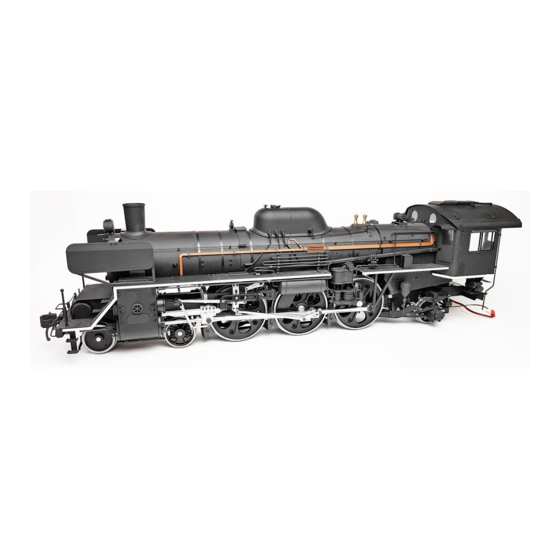
- Page 1 Build the Steam Locomotive Pack 03...
- Page 2 Editorial and design by Continuo Creative, 39-41 North Road, London N7 9DP. Published in the UK by De Agostini UK Ltd, Battersea Studios 2, 82 Silverthorne Road, London SW8 3HE. Published in the USA by De Agostini Publishing USA, Inc., 915 Broadway, Suite 609, New York, NY 10010.
- Page 3 Step by step: Stage The safety valves and Where your parts fit motion bars Motion bar Cylinder safety valve Valve guide Your parts Insert one of the cylinder safety valves into one of the cylinder covers on the rear plate, into the hole from which the screw was removed in Stage 12.
- Page 4 Check the two motion bars Position the front Round hole - front end Oval hole - rear for any burrs or flash left end of one of over from casting. the bars over the hole in the square projection on the cover.
- Page 5 Step by step: Stage The piston rods and Where your parts fit cylinder covers Front cylinder cover Piston assembly rod guide Your parts Piston assembly rod guide Apply synthetic rubber adhesive to Insert the piston rod into the hole in the the thin end of one of the piston rods.
- Page 6 Before the adhesive Apply synthetic rubber Front dries, place the assembly adhesive to the back on a flat surface. Check side of one of that the rod is vertical the front cylinder from all directions. covers, avoiding the circled hole. Screw one of the safety valves into the hole at the bottom of the Back...
- Page 7 Step by step: Stage The cylinder Where your parts fit side plates Drainage pipe Cylinder side plate Your parts Back Front On the front side of each inspection hatch, the projections at the top and bottom (outlined) are raised. Air valve wheels × 2 Tools Place a cylinder side plate, an air valve wheel, Inspection hatches ×...
- Page 8 Prepare one of the Turn the side air valve wheels and plate over and two hole covers. apply a small Position the wheel amount of instant with the projections adhesive to the at the arrowed backs of the pins. points when gluing to the side plate.
- Page 9 Before the glue The front end of dries, make sure the each drainage drainage pipes are pipe is thinner than the rear. vertical, as shown. Front Apply some synthetic rubber Fit the other drainage pipe adhesive to the to the bottom of the right three pins on one Apply some instant side plate in the same way.
- Page 10 Step by step: Stage The piston rods Where your parts fit and crossheads Piston rod Crosshead Your parts Insert a crosshead pin into one of the outer crossheads. Place a nut onto the thread of the crosshead pin. Tighten the nut. A 5.5mm socket Tools wrench will make...
- Page 11 Push the rod in as far as it will go, then wipe away any Repeat with the second rod and excess adhesive. crosshead. Keep both assemblies positioned with the rods vertical, as Apply some epoxy adhesive to one Insert the piston rod into the hole in the shown, until the glue dries.
- Page 12 Step by step: Stage The rear underframe Where your parts fit Rear underframe Your parts Tools Right rear underframe Expansion support bracket Phillips screwdriver Expansion support Soft cloth or towel 2 × 5mm screws × 13 2 × 8mm screws ×4 Left rear underframe Prepare the new parts along with the main underframe assembly.
- Page 13 The rear underframes are mostly symmetrical, the only exception being that when the underframes are laid flat, the front ends will be raised slightly, as shown here. Fit the right rear underframe Now fully tighten the Position the two underframes and between the support and main screws on each side of the Place the support...
- Page 14 Step by step: Stage Rear end beam Where your parts fit Rear end beam Rear plate and plate Your parts Half-tighten a 2 x 4mm screw into each of the indicated holes on one side of the underframe. Tools Place the rear end beam between the ends Rear end beam of the rear underframe, aligning the holes of Rear plate...
- Page 15 Align the two circled holes in the rear plate Hold the rear plate level, and secure it with Fully tighten the four with those in the end beam. two 2 × 4mm screws. screws on each side of the end of the rear underframe.
- Page 16 Step by step: Stage The motion frame Where your parts fit Motion frame Your parts Place the right and left motion Inside frame plates next to each other, as shown. The positions in the photo, left, show the inside and outside of the plates.
- Page 17 Arrange the motion Attach the left motion Rear frame components frame plate to the into the positions front plate with two Right shown here. 2 × 8mm screws. Only half-tighten the screws Holes at this point. Left Front Place the motion frame Turn the motion frame so Tighten screws Fully tighten the...
- Page 18 Step by step: Stage The equalising bars Where your parts fit Equalising bars Your parts Below the hole Hole There is no difference between the front and back of an equalising bar, but the top of it is flat while the bottom is angled. This picture shows the orientation of the equalising brackets.
- Page 19 Align the hole in Half-tighten a Tighten a the centre of one 2 × 8mm screw 2 × 3mm of the equalising into the hole screw into bars with the in the centre of each of the indicated hole in the bracket.
Need help?
Do you have a question about the Model Space C57 and is the answer not in the manual?
Questions and answers