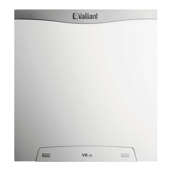
Vaillant VR 70 Installation Instructions Manual
Hide thumbs
Also See for VR 70:
- Installation instructions manual (12 pages) ,
- Operating and installation instructions (64 pages) ,
- Schematics and installation manual (44 pages)
Table of Contents

Summary of Contents for Vaillant VR 70
- Page 1 Installation instructions For the competent person Installation instructions VR 70 GB, IE Publisher/manufacturer Vaillant GmbH Berghauser Str. 40 D-42859 Remscheid Telefon 021 91 18‑0 Telefax 021 91 18‑28 10 info@vaillant.de www.vaillant.de...
-
Page 2: Table Of Contents
How it works ............5 Identification plate..........5 Checking the scope of delivery......5 Installation............6 Electrical installation........... 6 Setting the bus address ......... 7 Decommissioning..........7 Recycling and disposal........8 Customer service..........8 Technical data............8 Installation instructions VR 70 0020198787_00... -
Page 3: Safety
Any other use that is not specified in these instructions, or use beyond that specified in this document shall be considered improper 0020198787_00 VR 70 Installation instructions... - Page 4 1 Safety use. Any direct commercial or industrial use is also deemed to be improper. Caution. Improper use of any kind is prohibited. Installation instructions VR 70 0020198787_00...
-
Page 5: Notes On The Documentation
Information on the identific- Meaning Applicability of the instructions ation plate These instructions apply only to: Serial number For identification VR 70 – Article number VR 70 Product description Operating voltage Great Britain 0020184844 Power consumption Switching capacity for each... -
Page 6: Installation
Closing the product ally comes loose. Mount the front casing at the top of the wall socket. Use the fixing screw to secure the front casing. Installation instructions VR 70 0020198787_00... -
Page 7: Setting The Bus Address
Connect the eBUS line to the terminal strip in the con- Setting the bus address troller's wall socket. Address switch ▶ Assign a unique address to each VR 70 that is connec- ted, beginning with Address 1. Decommissioning Decommission the heating installation if you want to replace the product. -
Page 8: Recycling And Disposal
In this case, dispose of the batteries at a collection point for batteries. Customer service To ensure regular servicing, it is strongly recommended that arrangements are made for a Maintenance Agreement. Please contact Vaillant Service Solutions (0870 6060 777) for further details. Technical data Max. operating voltage 230 V ≤... - Page 12 0020198787_00 24.02.2015 Vaillant Ltd Nottingham Road Belper Derbyshire DE56 1JT Telephone 44 84 56 02 29 22 Vaillant Service Solutions 44 807 06 06 07 77 Spares Technical Enquiries 44 17 73 59 66 15 info@vaillant.co.uk technicalspares@groupservice.co.uk www.vaillant.co.uk © These instructions, or parts thereof, are protected by copyright and may be reproduced or distributed only with...


Need help?
Do you have a question about the VR 70 and is the answer not in the manual?
Questions and answers