Table of Contents
Advertisement
Quick Links
8JSA three-phase
synchronous motors
User's manual
Version: 1.00 (June 2019)
Model no.: MAMOT5-ENG
Translation of the original documentation
All values in this manual are current as of its creation. We reserve the right to change the contents of this manual
without notice. B&R Industrial Automation GmbH is not liable for technical or editorial errors and defects in this
manual. In addition, B&R Industrial Automation GmbH assumes no liability for damages that are directly or indirectly
attributable to the delivery, performance or use of this material. We point out that the software and hardware
designations and brand names of the respective companies used in this document are subject to general trademark,
brand or patent protection.
8JSA user's manual V1.00
1
Advertisement
Table of Contents

Related Manuals for B&R 8JSA2 Series


Summary of Contents for B&R 8JSA2 Series
- Page 1 8JSA three-phase synchronous motors User's manual Version: 1.00 (June 2019) Model no.: MAMOT5-ENG Translation of the original documentation All values in this manual are current as of its creation. We reserve the right to change the contents of this manual without notice.
-
Page 2: Table Of Contents
Table of contents Chapter 1 General information................... 5 1 Manual history..............................5 2 About this user's manual........................... 5 3 Safety................................. 5 3.1 Organization of safety notices........................5 3.2 Intended use..............................6 3.3 Reasonably foreseeable misuse........................6 3.4 General sources of danger.......................... 6 3.5 Provisions and safety guidelines........................9 3.6 Responsibilities of the operator........................9 3.7 Qualified personnel............................9 3.8 Safety notices............................... - Page 3 Table of contents 14.1 Speed-torque characteristic curves at 325 VDC DC bus voltage............45 14.2 Speed-torque characteristic curves at 560 VDC DC bus voltage............47 14.3 Speed-torque characteristic curves at 750 VDC DC bus voltage............48 14.4 Maximum shaft load..........................50 14.5 8JSA5 - Dimensions..........................51 15 8JSA6 - Technical data..........................
- Page 4 Table of contents Chapter 8 Standards, guidelines and certifications..........96 Chapter 9 Disposal.....................97 1 Safety................................97 1.1 Protective equipment..........................97 1.2 Rotor with rare earth magnets........................97 8JSA user's manual V1.00...
-
Page 5: Chapter 1 General Information
General information • Safety Chapter 1 • General information 1 Manual history Version Date Notes 1.00 2019-06-11 First edition Information: B&R makes every effort to keep user's manuals as current as possible. New versions are available in electronic form on the B&R website (www.br-automation.com). Check regularly to determine if you have the latest version. -
Page 6: Intended Use
General information • Safety 3.2 Intended use B&R motors and gear motors are components designed for installation in electrical systems or machines. They were designed, developed and manufactured for general industrial use. They are intended to be operated in covered rooms and under normal climatic conditions, which is usually the case in modern production halls. - Page 7 General information • Safety Danger! Risk of injury due to electric shock! If live parts are touched, there is immediate danger of fatal electric shock. If connections are connected or disconnected in the incorrect order or when the power is switched on, electric arcs can occur and persons and contacts can be damaged.
- Page 8 General information • Safety Danger! Danger of injury due to rotating or moving elements and loads! By rotating or moving elements, body parts can be drawn in or severed or subjected to impacts. • Do not stay in the danger zone during operation and secure it against access by unauthorized persons.
-
Page 9: Provisions And Safety Guidelines
General information • Safety 3.5 Provisions and safety guidelines To ensure proper commissioning and safe operation, be sure to observe the following: • General safety regulations • The applicable work safety regulations • National accident prevention regulations (e.g. VBG 4) for working with high-voltage systems •... -
Page 10: 8Jsa Three-Phase Synchronous Motors
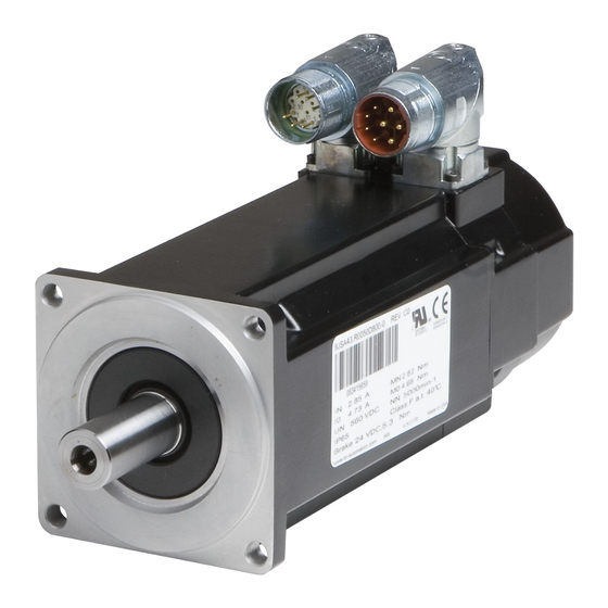
General information • 8JSA three-phase synchronous motors 4 8JSA three-phase synchronous motors B&R's 8JSA three-phase synchronous motors have been specially developed for use in high-performance appli- cations. Today, they are used to manufacture consumer goods and products in the plastics industry, packaging industry, metalworking industry, beverage and food industry and to palletize these products with handling systems. -
Page 11: Nameplate
General information • 8JSA three-phase synchronous motors 4.1 Nameplate The nameplate clearly identifies each motor. The serial number ensures traceability. The label on the motor housing includes the following information: Size 2 and 3 Size 4-7 Order code Revision xx.xxxxxxxxx-x UL-recognized component mark xx.xxxxxxxxx-x CE marking... -
Page 12: Chapter 2 Technical Data
Technical data • General description Chapter 2 • Technical data 1 General description Three-phase synchronous motors from the 8JSA series are permanent magnet, electronically commutated syn- chronous motors for applications that require excellent dynamic characteristics and positioning precision as well as compact size and reduced weight. -
Page 13: 8Jsa Order Key
Technical data • 8JSA order key 2 8JSA order key ee nnn gg - Cooling / Construction type A ... Self-cooling see "Cooling / Construction type" on page 15 Size Valid values: 2, 3, 4, 5, 6, 7 see "Size (c)" on page 15 Length Valid values: 1, 2, 3, 4, 5 see "Length (d)"... -
Page 14: Example Order 1
Technical data • 8JSA order key 2.1 Example order 1 A three-phase synchronous motor (type 8JSA44) with a nominal speed of 4000 rpm was selected for an application. The motor should also be equipped with a holding brake, a keyed shaft and a 2048-line EnDat single-turn encoder. The code (ee) for the encoder system is E6. -
Page 15: Cooling / Construction Type
Technical data • Length (d) 3 Cooling / Construction type gg - see "Order key" on page 13 8JSA Cooling type 8JSA is self-cooling and has a slim, elongated design. These motors must be attached to the machine with the mounting flange, which also serves as a cooling surface. 4 Size (c) gg - see "Order key"... -
Page 16: Motor Encoder System (Ee)
Technical data • Motor encoder system (ee) 6 Motor encoder system (ee) gg - see "Order key" on page 13 8JS three-phase synchronous motors are available with EnDat encoders as well as resolvers. The encoder system is specified as part of the model number in the form of a 2-digit code (ee). Analog and digital transfer A resolver is an analog encoder system. -
Page 17: Resolver
Technical data • Motor encoder system (ee) Motor sizes 4 - 7 Encoder type / Order code 1) 2) Operating principle Inductive Inductive EnDat protocol Functional safety Single-turn / Multi-turn Revolutions 4096 Resolution [bits single-turn / bits mul- ti-turn] 19/0 19/12 Precision ["] Switching frequency ≥... -
Page 18: Nominal Speed (Nnn)
Technical data • Motor options (ff) 7 Nominal speed (nnn) gg - see "Order key" on page 13 The nominal speed is listed as part of the model number in the form of a 3-digit code (nnn). Order code (nnn) Nominal speed n [rpm] 1800... -
Page 19: Connection Direction (Ff)
Technical data • Motor options (ff) 8.1 Connection direction (ff) 8JSA three-phase synchronous motors can be delivered with angular, axial swivel connectors. Angled built-in connector Connection direction: Angled (swivel connector) Encoder and power cable: Separated with own connections Check the angle specifications (max. 200-220°) and the feasibility with regard to your re- quirements using the CAD configurator (cad.br-automation.com). -
Page 20: Holding Brake (Ff)
Technical data • Motor options (ff) 8.3 Holding brake (ff) Operating principle The holding brake is a spring-applied brake controlled by a B&R drive system. Based on principle, this type of holding brake exhibits a minimal amount of backlash. The brake is designed as a holding brake. It not permitted to be used for operational braking! Under these condi- tions, the brake has a service life of approximately 5,000,000 cycles (opening and closing the brake is one cycle). -
Page 21: Shaft End
Technical data • Special motor options (gg) 8.4 Shaft end All 8JSA three-phase synchronous motor shafts comply with DIN 748 and are available with a smooth shaft end. Motor options (ff) - Overview (order code) see "Motor options (ff)" on page 18 Variants Smooth shaft end A smooth shaft end is used for a force-fit shaft-hub connection and guarantees a back-... -
Page 22: General Motor Data
Technical data • General motor data 10 General motor data General information Cooling type A C-UR-US listed Electrical properties Mains input voltage on servo drive 3x 400 VAC ... 3x 480 VAC ±10% Connection type speedtec circular connector from Intercontec Motor connection Size 1 Encoder connection... -
Page 23: Reduction Of Nominal Values Depending On The Motor Option
Technical data • General motor data 10.1 Reduction of nominal values depending on the motor option The nominal values are reduced depending on the motor option selected (stall torque M and nominal torque M for the motor as seen in the following table (all values in [Nm]): Motor option (ff) Motor 8JSA22.R0nnnffgg-0... -
Page 24: Formula Symbols
Technical data • General motor data 10.2 Formula symbols Term Symbol Unit Description Nominal speed Nominal speed of the motor Nominal torque The nominal torque is output by the motor (n = n ) when the nominal current is being drawn. This is possible for any length of time if the ambient conditions are correct. -
Page 25: Power Dissipation
Technical data • General motor data 10.3 Power dissipation Power from the servo motors is dissipated via the motor flange and the surface of the motor. The following factors are important to ensure optimal heat dissipation: • Thermally open installation •... -
Page 26: 8Jsa2 - Technical Data
Technical data • 8JSA2 - Technical data 11 8JSA2 - Technical data Model number 8JSA22.ee080ffgg-0 8JSA24.ee080ffgg-0 Motor Nominal speed n [rpm] 8000 Number of pole pairs Nominal torque M [Nm] 0.63 1.06 Nominal power P Nominal current I 1.04 1.67 Stall torque M [Nm] 0.84... -
Page 27: Speed-Torque Characteristic Curves At 560 Vdc Dc Bus Voltage
Technical data • 8JSA2 - Technical data 8JSA24.eennnffgg-0 (0/5.6) (2227/5.599) = 8000 rpm (0/1.41) (5638/0) 1000 2000 3000 4000 5000 6000 7000 TChar version: 0124 dT ... 100K Speed in rpm DB version: 2017 09 18 dT ... 60K dT ... 60K 11.2 Speed-torque characteristic curves at 560 VDC DC bus voltage 8JSA22.eennnffgg-0 = 8000 rpm... -
Page 28: Speed-Torque Characteristic Curves At 750 Vdc Dc Bus Voltage
Technical data • 8JSA2 - Technical data 8JSA24.eennnffgg-0 (0/5.6) (4820/5.597) = 8000 rpm (8100/1.905) (8000/2.002) (0/1.41) (8000/1.06) 1000 2000 3000 4000 5000 6000 7000 8000 9000 TChar version: 0124 dT ... 100K Speed in rpm DB version: 2017 09 18 dT ... -
Page 29: Maximum Shaft Load
Technical data • 8JSA2 - Technical data 8JSA24.eennnffgg-0 (0/5.6) (7371/5.595) (8100/4.888) = 8000 rpm (8000/4.985) (0/1.41) (8000/1.06) 1000 2000 3000 4000 5000 6000 7000 8000 9000 TChar version: 0124 dT ... 100K Speed in rpm DB version: 2017 09 18 dT ... -
Page 30: 8Jsa2 - Dimensions
Technical data • 8JSA2 - Technical data 11.5 8JSA2 - Dimensions EnDat/Resolver feedback Extension of K and K depending on the mo- tor option [mm] Encoder assignments E4, E5, E8, E9 Model number Holding brake 8JSA21.eennnffgg-0 95.4 95.4 76.1 34.1 8JSA22.eennnffgg-0 114.4 114.4... -
Page 31: 8Jsa3 - Technical Data
Technical data • 8JSA3 - Technical data 12 8JSA3 - Technical data Model number 8JSA31.ee050ffgg-0 8JSA32.ee030ffgg-0 8JSA32.ee055ffgg-0 8JSA33.ee045ffgg-0 Motor Nominal speed n [rpm] 5000 3000 5500 4500 Number of pole pairs Nominal torque M [Nm] 0.95 1.81 2.29 Nominal power P 1079 Nominal current I 1.12... - Page 32 Technical data • 8JSA3 - Technical data 8JSA32.eennnffgg-0 (1384/8.3) (0/8.2) (0/8.2) (589/8.2) = 3000 rpm = 5500 rpm (0/2) (0/2) (2562/0) (3899/0) 1000 1500 2000 2500 3000 3500 4000 4500 TChar version: 0124 dT ... 100K Speed in rpm DB version: 2017 09 18 dT ...
-
Page 33: Speed-Torque Characteristic Curves At 560 Vdc Dc Bus Voltage
Technical data • 8JSA3 - Technical data 12.2 Speed-torque characteristic curves at 560 VDC DC bus voltage 8JSA31.eennnffgg-0 (0/4.5) (3046/4.5) = 5000 rpm (5000/2.373) (0/1.15) (5000/0.95) (7340/0) 1000 2000 3000 4000 5000 6000 7000 8000 TChar version: 0124 dT ... 100K Speed in rpm DB version: 2017 09 18 dT ... -
Page 34: Speed-Torque Characteristic Curves At 750 Vdc Dc Bus Voltage
Technical data • 8JSA3 - Technical data 8JSA33.eennnffgg-0 = 4500 rpm (0/11.8) (2748/11.8) (4500/4.587) (0/2.79) (4500/2.29) (5666/0) 1000 2000 3000 4000 5000 6000 7000 TChar version: 0124 dT ... 100K Speed in rpm DB version: 2017 09 18 dT ... 60K dT ... - Page 35 Technical data • 8JSA3 - Technical data 8JSA32.eennnffgg-0 (4941/8.3) (0/8.2) (0/8.2) (2962/8.2) = 3000 rpm = 5500 rpm (3000/8.149) (5500/7.161) (8100/2.432) (0/2) (0/2) (3000/1.81) (5500/1.6) (5537/0) 1000 2000 3000 4000 5000 6000 7000 8000 9000 TChar version: 0124 dT ... 100K Speed in rpm DB version: 2017 09 18 dT ...
-
Page 36: Maximum Shaft Load
Technical data • 8JSA3 - Technical data 12.4 Maximum shaft load Note the information in section "Load capacity of the shaft end and bearing" on page 70 of chapter "Installation conditions". 1000 1500 3000 4500 6000 (Smooth shaft) rmax (Keyed shaft) rmax Distance x [mm] Maximum axial force: F... -
Page 37: 8Jsa3 - Dimensions
Technical data • 8JSA3 - Technical data 12.5 8JSA3 - Dimensions EnDat/Resolver feedback Extension of K and K depending on the mo- tor option [mm] Encoder assignments E4, E5, E8, E9 Model number Holding brake 8JSA31.eennnffgg-0 31.5 8JSA32.eennnffgg-0 31.5 8JSA33.eennnffgg-0 31.5 8JSA user's manual V1.00... -
Page 38: 8Jsa4 - Technical Data
Technical data • 8JSA4 - Technical data 13 8JSA4 - Technical data Model number 8JSA42.ee035ffgg-0 8JSA43.ee050ffgg-0 8JSA44.ee040ffgg-0 Motor Nominal speed n [rpm] 3500 5000 4000 Number of pole pairs Nominal torque M [Nm] 2.74 2.94 3.69 Nominal power P 1004 1539 1546 Nominal current I... - Page 39 Technical data • 8JSA4 - Technical data 8JSA43.eennnffgg-0 = 5000 rpm (0/18.8) (1476/18.8) (0/4.8) (3600/0) 1000 1500 2000 2500 3000 3500 4000 TChar version: 0124 dT ... 100K Speed in rpm DB version: 2017 09 18 dT ... 60K dT ... 60K 8JSA44.eennnffgg-0 = 4000 rpm (0/23.8)
-
Page 40: Speed-Torque Characteristic Curves At 560 Vdc Dc Bus Voltage
Technical data • 8JSA4 - Technical data 13.2 Speed-torque characteristic curves at 560 VDC DC bus voltage 8JSA42.eennnffgg-0 (0/13.1) (1953/13.1) = 3500 rpm (3500/5.657) (0/3.42) (3500/2.74) (4945/0) 1000 2000 3000 4000 5000 6000 TChar version: 0124 dT ... 100K Speed in rpm DB version: 2017 09 18 dT ... -
Page 41: Speed-Torque Characteristic Curves At 750 Vdc Dc Bus Voltage
Technical data • 8JSA4 - Technical data 8JSA44.eennnffgg-0 = 4000 rpm (0/23.8) (2507/23.8) (4000/11.075) (0/5.88) (4000/3.69) (5222/0) 1000 2000 3000 4000 5000 6000 TChar version: 0124 dT ... 100K Speed in rpm DB version: 2017 09 18 dT ... 60K dT ... - Page 42 Technical data • 8JSA4 - Technical data 8JSA43.eennnffgg-0 = 5000 rpm (0/18.8) (4148/18.8) (5000/14.629) (6100/10.177) (0/4.8) (5000/2.94) 1000 2000 3000 4000 5000 6000 7000 TChar version: 0124 dT ... 100K Speed in rpm DB version: 2017 09 18 dT ... 60K dT ...
-
Page 43: Maximum Shaft Load
Technical data • 8JSA4 - Technical data 13.4 Maximum shaft load Note the information in section "Load capacity of the shaft end and bearing" on page 70 of chapter "Installation conditions". 1300 1200 1100 1000 1000 1500 3000 4500 6000 (Smooth shaft) rmax (Keyed shaft) -
Page 44: 8Jsa4 - Dimensions
Technical data • 8JSA4 - Technical data 13.5 8JSA4 - Dimensions EnDat/Resolver feedback Extension of K and K depending on the mo- tor option [mm] Encoder assignments E6, E7, EA, EB Model number Holding brake 8JSA41.eennnffgg-0 118.8 136.8 96.4 33.5 8JSA42.eennnffgg-0 147.8 165.8... -
Page 45: 8Jsa5 - Technical Data
Technical data • 8JSA5 - Technical data 14 8JSA5 - Technical data Model number 8JSA51.ee045ffgg-0 8JSA52.ee045ffgg-0 8JSA54.ee028ffgg-0 8JSA54.ee050ffgg-0 Motor Nominal speed n [rpm] 4500 2750 5000 Number of pole pairs Nominal torque M [Nm] 2.89 5.02 11.17 6.92 Nominal power P 1362 2366 3217... - Page 46 Technical data • 8JSA5 - Technical data 8JSA52.eennnffgg-0 = 4500 rpm (0/29.9) (1444/29.9) (0/8.5) (3071/0) 1000 1500 2000 2500 3000 3500 TChar version: 0124 dT ... 100K Speed in rpm DB version: 2017 09 18 dT ... 60K dT ... 60K 8JSA54.eennnffgg-0 (0/54.5) (0/54.5)
-
Page 47: Speed-Torque Characteristic Curves At 560 Vdc Dc Bus Voltage
Technical data • 8JSA5 - Technical data 14.2 Speed-torque characteristic curves at 560 VDC DC bus voltage 8JSA51.eennnffgg-0 = 4500 rpm (0/15.7) (4758/15.699) (4500/15.699) (6100/11.018) (0/4.83) (4500/2.89) 1000 2000 3000 4000 5000 6000 7000 TChar version: 0124 dT ... 100K Speed in rpm DB version: 2017 09 18 dT ... -
Page 48: Speed-Torque Characteristic Curves At 750 Vdc Dc Bus Voltage
Technical data • 8JSA5 - Technical data 8JSA54.eennnffgg-0 (0/54.5) (0/54.5) (1829/54.5) (3155/53.9) = 2750 rpm = 5000 rpm (2750/23.108) (0/14.4) (0/14.4) (5000/15.413) (2750/11.17) (5000/6.92) (5487/0) (3325/0) 1000 2000 3000 4000 5000 6000 TChar version: 0124 dT ... 100K Speed in rpm DB version: 2017 09 18 dT ... - Page 49 Technical data • 8JSA5 - Technical data 8JSA52.eennnffgg-0 = 4500 rpm (0/29.9) (4057/29.9) (4500/25.628) (6100/12.562) (0/8.5) (4500/5.02) 1000 2000 3000 4000 5000 6000 7000 TChar version: 0124 dT ... 100K Speed in rpm DB version: 2017 09 18 dT ... 60K dT ...
-
Page 50: Maximum Shaft Load
Technical data • 8JSA5 - Technical data 14.4 Maximum shaft load Note the information in section "Load capacity of the shaft end and bearing" on page 70 of chapter "Installation conditions". 1300 1200 1100 1000 1000 1500 3000 4500 6000 (Smooth shaft) rmax (Keyed shaft) -
Page 51: 8Jsa5 - Dimensions
Technical data • 8JSA5 - Technical data 14.5 8JSA5 - Dimensions EnDat/Resolver feedback Extension of K and K depending on the mo- tor option [mm] Encoder assignments E6, E7, EA, EB Holding brake Model number 8JSA51.eennnffgg-0 127.5 105.3 8JSA52.eennnffgg-0 158.5 136.3 8JSA53.eennnffgg-0 189.5... -
Page 52: 8Jsa6 - Technical Data
Technical data • 8JSA6 - Technical data 15 8JSA6 - Technical data Model number 8JSA62.ee030ffgg-0 8JSA63.ee023ffgg-0 8JSA64.ee030ffgg-0 8JSA65.ee025ffgg-0 Motor Nominal speed n [rpm] 3000 2250 3000 2500 Number of pole pairs Nominal torque M [Nm] 9.14 13.61 15.4 Nominal power P 2871 3207 4838... - Page 53 Technical data • 8JSA6 - Technical data 8JSA63.eennnffgg-0 = 2250 rpm (0/59.3) (708/59.3) (0/16.8) (1665/0) 1000 1200 1400 1600 1800 TChar version: 0124 dT ... 100K Speed in rpm DB version: 2017 09 18 dT ... 60K dT ... 60K 8JSA64.eennnffgg-0 = 3000 rpm (0/76.6)
-
Page 54: Speed-Torque Characteristic Curves At 560 Vdc Dc Bus Voltage
Technical data • 8JSA6 - Technical data 8JSA65.eennnffgg-0 (0/93.2) (947/93.2) = 2500 rpm (0/25) (1933/0) 1000 1500 2000 2500 TChar version: 0124 dT ... 100K Speed in rpm DB version: 2017 09 18 dT ... 60K dT ... 60K 15.2 Speed-torque characteristic curves at 560 VDC DC bus voltage 8JSA62.eennnffgg-0 (0/41.1) (1745/41.1) - Page 55 Technical data • 8JSA6 - Technical data 8JSA63.eennnffgg-0 = 2250 rpm (0/59.3) (1390/59.3) (2250/26.312) (0/16.8) (2250/13.61) (2895/0) 1000 1500 2000 2500 3000 3500 TChar version: 0124 dT ... 100K Speed in rpm DB version: 2017 09 18 dT ... 60K dT ...
-
Page 56: Speed-Torque Characteristic Curves At 750 Vdc Dc Bus Voltage
Technical data • 8JSA6 - Technical data 8JSA65.eennnffgg-0 (0/93.2) (1782/93.2) = 2500 rpm (2500/51.474) (0/25) (2500/19) (3362/0) 1000 1500 2000 2500 3000 3500 4000 TChar version: 0124 dT ... 100K Speed in rpm DB version: 2017 09 18 dT ... 60K dT ... - Page 57 Technical data • 8JSA6 - Technical data 8JSA63.eennnffgg-0 = 2250 rpm (0/59.3) (2051/59.3) (2250/52.34) (0/16.8) (2250/13.61) (3598/0) 1000 1500 2000 2500 3000 3500 4000 TChar version: 0124 dT ... 100K Speed in rpm DB version: 2017 09 18 dT ... 60K dT ...
-
Page 58: Maximum Shaft Load
Technical data • 8JSA6 - Technical data 8JSA65.eennnffgg-0 (0/93.2) (2612/93.2) = 2500 rpm (2500/93.2) (0/25) (2500/19) (4178/0) 1000 1500 2000 2500 3000 3500 4000 4500 TChar version: 0124 dT ... 100K Speed in rpm DB version: 2017 09 18 dT ... 60K dT ... -
Page 59: 8Jsa6 - Dimensions
Technical data • 8JSA6 - Technical data 15.5 8JSA6 - Dimensions EnDat/Resolver feedback Extension of K and K depending on the mo- tor option [mm] Encoder assignments E6, E7, EA, EB Holding brake Model number 8JSA62.eennnffgg-0 153.7 172.2 130.5 47.5 8JSA63.eennnffgg-0 178.7 197.2... -
Page 60: 8Jsa7 - Technical Data
Technical data • 8JSA7 - Technical data 16 8JSA7 - Technical data Model number 8JSA72.ee020ffgg-0 8JSA73.ee024ffgg-0 8JSA74.ee018ffgg-0 Motor Nominal speed n [rpm] 2000 2400 1800 Number of pole pairs Nominal torque M [Nm] 23.4 28.2 39.3 Nominal power P 4901 7087 7408 Nominal current I... - Page 61 Technical data • 8JSA7 - Technical data 8JSA73.eennnffgg-0 (0/167.9) (731/167.9) = 2400 rpm (0/41.6) (1679/0) 1000 1200 1400 1600 1800 2000 TChar version: 0124 dT ... 100K Speed in rpm DB version: 2017 09 18 dT ... 60K dT ... 60K 8JSA74.eennnffgg-0 = 1800 rpm (0/214.6)
-
Page 62: Speed-Torque Characteristic Curves At 560 Vdc Dc Bus Voltage
Technical data • 8JSA7 - Technical data 16.2 Speed-torque characteristic curves at 560 VDC DC bus voltage 8JSA72.eennnffgg-0 = 2000 rpm (0/119.3) (1147/119.3) (2000/49.529) (0/30) (2000/23.4) (2667/0) 1000 1500 2000 2500 3000 TChar version: 0124 dT ... 100K Speed in rpm DB version: 2017 09 18 dT ... -
Page 63: Speed-Torque Characteristic Curves At 750 Vdc Dc Bus Voltage
Technical data • 8JSA7 - Technical data 8JSA74.eennnffgg-0 = 1800 rpm (0/214.6) (1061/214.6) (1800/80.482) (0/52.5) (1800/39.3) (2186/0) 1000 1500 2000 2500 TChar version: 0124 dT ... 100K Speed in rpm DB version: 2017 09 18 dT ... 60K dT ... 60K 16.3 Speed-torque characteristic curves at 750 VDC DC bus voltage 8JSA72.eennnffgg-0 = 2000 rpm... - Page 64 Technical data • 8JSA7 - Technical data 8JSA73.eennnffgg-0 (0/167.9) (1942/167.898) = 2400 rpm (2400/123.349) (0/41.6) (2400/28.2) (3629/0) 1000 1500 2000 2500 3000 3500 4000 TChar version: 0124 dT ... 100K Speed in rpm DB version: 2017 09 18 dT ... 60K dT ...
-
Page 65: Maximum Shaft Load
Technical data • 8JSA7 - Technical data 16.4 Maximum shaft load Note the information in section "Load capacity of the shaft end and bearing" on page 70 of chapter "Installation conditions". 2500 2000 1500 1000 1500 3000 1000 4500 6000 (Smooth shaft) rmax (Keyed shaft) -
Page 66: 8Jsa7 - Dimensions
Technical data • 8JSA7 - Technical data 16.5 8JSA7 - Dimensions EnDat/Resolver feedback Extension of K and K depending on the mo- tor option [mm] Encoder assignments E6, E7, EA, EB Holding brake Model number 8JSA72.eennnffgg-0 192.5 201.7 164.5 51.6 8JSA73.eennnffgg-0 226.5 235.7... -
Page 67: Chapter 3 Transport And Storage
Transport and storage Chapter 3 • Transport and storage During transport and storage, the product must be protected against undue stress (mechanical loads, temperature, moisture, corrosive atmospheres, etc.). If necessary, also protect existing electrostatically sensitive components such as the encoders in motors against electrostatic discharge (ESD). - Page 68 Transport and storage Storage Caution! Damage caused by degraded material properties. Storage for long periods of time or storage under improper conditions can cause certain materials to age prematurely, to have degraded properties and to become damaged. Damaged components can then result in further damage to property.
-
Page 69: Chapter 4 Installation Conditions
Installation conditions • Installation and cooling Chapter 4 • Installation conditions Before every commissioning procedure, the motor must be checked by qualified personnel. The check must include the proper condition in terms of mounting and installation, the installation conditions and safe operation. Operating conditions Rating class, operating mode per EN 60034-1 S1 - Continuous operation... -
Page 70: Load Capacity Of The Shaft End And Bearing
Installation conditions • Load capacity of the shaft end and bearing Caution! Personal injury and damage to property due to failure or overheating of the drive. If the maximum permissible operating temperature is exceeded, a drive defect with consequential dam- age is very probable. - Page 71 Installation conditions • Load capacity of the shaft end and bearing ..Radial force ..Axial force x.... Distance between the motor flange and the point where radial force F is applied. Figure 1: Definition of shaft load 8JSA user's manual V1.00...
-
Page 72: Chapter 5 Installation And Connection
Installation and connection • Safety Chapter 5 • Installation and connection 1 Before installation Read this user's manual completely before performing any work activities. In addition, take into account the technical documentation for all other machine components as well as the finished machine. - Page 73 Installation and connection • Safety Danger! Risk of injury due to electric shock! If live parts are touched, there is immediate danger of fatal electric shock. If connections are connected or disconnected in the incorrect order or when the power is switched on, electric arcs can occur and persons and contacts can be damaged.
- Page 74 Installation and connection • Safety Danger! Danger of injury due to rotating or moving elements and loads! By rotating or moving elements, body parts can be drawn in or severed or subjected to impacts. • Do not stay in the danger zone during operation and secure it against access by unauthorized persons.
-
Page 75: Noise Emissions
Installation and connection • Safety Warning! Risk of burns due to hot surfaces! Touching hot surfaces (e.g. motor and gearbox housings, as well as connected components), can lead to very severe burns due to the very high temperature of these parts. •... -
Page 76: Shaft End And Bearing
Installation and connection • Shaft end and bearing 3 Shaft end and bearing The motor shaft is supported on both sides with grease-lubricated grooved ball bearings. Protect the motor from damage due to excessive radial and axial forces! Under all circumstances, avoid the following loads on the front shaft end or the rear motor housing cover: •... -
Page 77: Installing In The System
Installation and connection • Installing in the system 4 Installing in the system Before working on motors, gearboxes or servo drives or in the danger zone of your machine, disconnect them completely from the power system and secure them against being switched on again by other persons or automatic systems. -
Page 78: Connecting And Disconnecting The Motor
Installation and connection • Connecting and disconnecting the motor 5 Connecting and disconnecting the motor Observe the following safety guidelines and instructions when connecting and disconnecting the motor: The protective ground conductor must be connected via the power connection or motor connector. Danger! Personal injury and damage to property due to missing ground potential! If there is no proper ground potential on the motor housing or servo drive, fault currents can lead to... -
Page 79: Cables And Connectors
Installation and connection • Connecting and disconnecting the motor Warning! Risk of burns due to hot surfaces! Touching hot surfaces (e.g. motor and gearbox housings, as well as connected components), can lead to very severe burns due to the very high temperature of these parts. •... -
Page 80: Order Of Connection
Installation and connection • Connecting and disconnecting the motor Cable clamp (A) • A = Max. 300 mm along longitudinal axis of connector • The connection must be free of force and torque. • Movement relative to the connector is not permitted! •... -
Page 81: Connecting Connectors Properly
Installation and connection • Connecting and disconnecting the motor Separate connections for motor and encoder Connecting 1. Disconnect the machine from the power system and secure it against being switched on again. 2. Connect the cable to the drive system (ACOPOS). 3. -
Page 82: Connection Type
Installation and connection • Connecting and disconnecting the motor 5.3.2 Screw terminal The screw terminal does not require a tool. During installation, make sure that the connector is screwed on straight. If strong vibrations (>4-6 g) are expected during operation, the screw connection must be secured with a vibration ring. - Page 83 Installation and connection • Connecting and disconnecting the motor 5.4.2.2 EnDat connection - Pinout EnDat 2.1 Color Description Function Blue Sense +5 V Sense output +5 V White Sense COM Sense output 0 V Encoder power supply +5 Brown/Green +5 V output / 0.25A Violet Clock input Yellow...
-
Page 84: Chapter 6 Commissioning And Operation
Commissioning and operation • Safety Chapter 6 • Commissioning and operation 1 Before commissioning and operation Read this user's manual completely before starting any commissioning activities or operation. In addition, take into account the technical documentation for all other machine components (e.g. the B&R drive system) as well as the finished machine. - Page 85 Commissioning and operation • Safety Danger! Risk of injury due to electric shock! If live parts are touched, there is immediate danger of fatal electric shock. If connections are connected or disconnected in the incorrect order or when the power is switched on, electric arcs can occur and persons and contacts can be damaged.
- Page 86 Commissioning and operation • Safety Danger! Danger of injury due to rotating or moving elements and loads! By rotating or moving elements, body parts can be drawn in or severed or subjected to impacts. • Do not stay in the danger zone during operation and secure it against access by unauthorized persons.
-
Page 87: Reversing Operation
Commissioning and operation • Safety Warning! Risk of burns due to hot surfaces! Touching hot surfaces (e.g. motor and gearbox housings, as well as connected components), can lead to very severe burns due to the very high temperature of these parts. •... -
Page 88: Verification
Commissioning and operation • Verification Danger! Personal injury and damage to property due to non-intended use of the holding brake! If the holding brake is used differently than intended, functional failures and accidents involving per- sonal injury or damage to property are possible. •... -
Page 89: To Verify During Commissioning
Commissioning and operation • Faults during operation 3.2 To verify during commissioning During commissioning, check the following: • The functionality of all the motor's components and assemblies (e.g. protective equipment, encoder, brake, cooling, gearbox, etc.) has been verified. • The operating conditions (see chapter "Installation conditions") are observed. •... - Page 90 Commissioning and operation • Faults during operation If necessary, contact B&R. For this, the following information should be provided: • Order description and serial number (see nameplate) • Type and extent of fault • Circumstances under which the fault occurred •...
-
Page 91: Chapter 7 Inspection And Maintenance
Inspection and maintenance • Safety Chapter 7 • Inspection and maintenance Various operating conditions (e.g. operating mode, temperature, speed, load, mounting orientation), can have a significant impact on the service life of lubricants, seals and bearings. Depending on the pollution degree, clean regularly on site to ensure heat is being dissipated properly, for example. The following tasks are the responsibility of the operator: •... - Page 92 Inspection and maintenance • Safety Danger! Risk of injury due to electric shock! If live parts are touched, there is immediate danger of fatal electric shock. If connections are connected or disconnected in the incorrect order or when the power is switched on, electric arcs can occur and persons and contacts can be damaged.
- Page 93 Inspection and maintenance • Safety Danger! Danger of injury due to rotating or moving elements and loads! By rotating or moving elements, body parts can be drawn in or severed or subjected to impacts. • Do not stay in the danger zone during operation and secure it against access by unauthorized persons.
-
Page 94: Motor Bearing And Holding Brake
Inspection and maintenance • Motor bearing and holding brake Warning! Risk of burns due to hot surfaces! Touching hot surfaces (e.g. motor and gearbox housings, as well as connected components), can lead to very severe burns due to the very high temperature of these parts. •... -
Page 95: Oil Seal
Inspection and maintenance • Cleaning Note: Loaded braking during an emergency stop is permitted but reduces its service life. 3 Oil seal Motors can optionally be equipped with an oil seal (form A per DIN 3760). The motors thus satisfy the requirements for IP65 protection per EN 60034-5. - Page 96 Standards, guidelines and certifications Chapter 8 • Standards, guidelines and certifications The motors are intended for use in commercial plants and subject to the following standards and guidelines: Standards EN 60034-1 Rotating electrical machines - Rating and performance EN 60034-5 Degrees of protection provided by integral design of rotating electrical machines EN 60529 Degrees of protection provided by enclosures...
- Page 97 Disposal • Safety Chapter 9 • Disposal Separation of materials To ensure that devices can be recycled in an environmentally friendly manner, it is necessary to separate out the different materials. Disposal must be carried out in accordance with applicable legal regulations. Component Disposal Note...
- Page 98 Publishing information Publishing information B&R Industrial Automation GmbH B&R Strasse 1 5142 Eggelsberg Austria Telephone: +43 7748 6586-0 Fax: +43 7748 6586-26 office@br-automation.com 8JSA user's manual V1.00...
Need help?
Do you have a question about the 8JSA2 Series and is the answer not in the manual?
Questions and answers