Table of Contents
Advertisement
Quick Links
Advertisement
Table of Contents

Summary of Contents for Motorline professional MD100
- Page 1 MD100 MD100 INSTALLER AND USER’S MANUAL v3.0 REV. 11/2019...
-
Page 2: Table Of Contents
00. CONTENT 01. SAFETY INSTRUCTIONS INDEX ATTENTION: 01. SAFETY INSTRUCTIONS This product is certified in accordance with European 02. MAGNETIC DETECTOR Community (EC) safety standards. TECHNICAL CHARACTERISTICS 03. PRE INSTALLATION This product complies with Directive 2011/65/EU of the PRECAUTIONS TO HAVE European Parliament and of the Council, of 8 June 2011, on the restriction of the use of certain hazardous substances in 04. -
Page 3: Safety Instructions
01. SAFETY INSTRUCTIONS GENERAL WARNINGS the motorized door or gate from being triggered involuntarily. • This manual contains very important safety and usage information. WARNINGS FOR TECHNICIANS very important. Read all instructions carefully before beginning the installation/usage procedures and keep this manual in a safe place •... - Page 4 01. SAFETY INSTRUCTIONS RESPONSABILITY • Attach the permanent label for the manual release as close as possible to the release mechanism. • Supplier disclaims any liability if: • Disconnect means, such as a switch or circuit breaker on the electrical •...
-
Page 5: Magnetic Detector
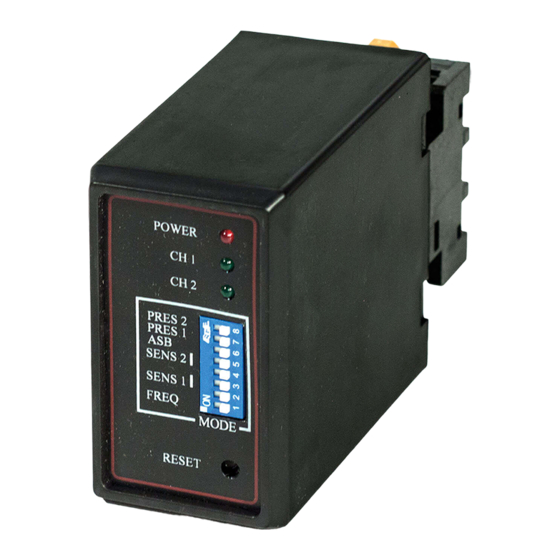
03. PRE INSTALLATION PRECAUTIONS TO HAVE TECHNICAL CHARACTERISTICS MD100 is a vehicle magnetic detector that detects the presence of large metal objects (cars, trucks, wagons) even when the vehicle is not moving. Please pay attention to the supply voltage of the equipment. -
Page 6: Installation
Fill the crack with epoxy resin or bitumen. INSERT MD100 Loosen the connector and insert a suitable plate. Retighten the connector. Attach the MD100 to the plate and remove the cover. ∅4mm MAKE CONNECTIONS Connect the cables according to the wiring diagram on the next page. -
Page 7: Connection Scheme
05. CONNECTION SCHEME 06. PROGRAMMING COMPONENT CONNECTIONS FREQUENCY ADJUSTMENT Channel 1 frequency adjustment can be achieved by Dip switch # 1 on the front panel. This depends on the geometric shape, size and number of turns of the loop. Frequency Dip switch #1 1 2 3 4 5 6 7 8 High... -
Page 8: Automatic Increase In Sensitivity 7A
06. PROGRAMMING 07. INDICATORS CONTACT RELAY MODE AUTOMATIC INCREASE IN SENSITIVITY Automatic sensitivity increase causes the sensitivity level to be maximum. This level is maintained as Status Channel 1 relay Channel 2 relay long as the car is present on the loop. When the vehicle leaves the loop and no longer detects, the sensitivity level returns to the preselected level.
Need help?
Do you have a question about the MD100 and is the answer not in the manual?
Questions and answers