Table of Contents
Advertisement
Advertisement
Table of Contents

Related Manuals for Textron Steiner 430 MAX


Summary of Contents for Textron Steiner 430 MAX
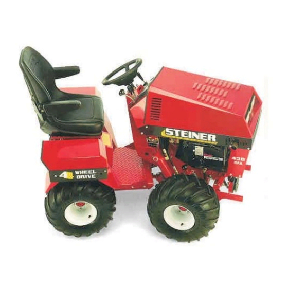
- Page 1 4 - WHEEL DRIVE TRACTOR Starting Serial No. 7001 Use this manual for 75-70004 25hp Kohler 430 Owner / Operator's Manual CAUTION Avoid injuries. Read and understand Operator’s manual before operating tractor or equipment. It contains instructions for safe operation. Form # 09-367...
- Page 2 CAUTION • READ AND UNDERSTAND OPERATORS MANUAL BEFORE OPERATING OR SERVICING. • OBEY ALL SAFETY INSTRUCTIONS. FAILURE TO DO SO MAY RESULT IN INJURY TO YOU OR OTHERS. • BE SURE MACHINE IS IN SAFE OPERATING CONDITION BEFORE USE. • INSPECT MACHINE DAILY. REPLACE ALL WORN OR DAMAGED PARTS.
-
Page 3: Table Of Contents
TABLE OF CONTENTS INTRODUCTION SECTION 1 Page Introduction....................1-1 Specifications ....................1-2 SAFETY SECTION 2 General Safety ...................2-1 Safety Practices and Training..............2-2 Safety Decals.....................2-4 PRE-START INSTRUCTIONS SECTION 3 Starting Instructions...................3-1 Fuels and Oils ....................3-2 OPERATION SECTION 4 Controls .....................4-1 Operating Precautions................4-4 Operating Instructions ................4-4 SERVICE SECTION 5 Service Schedule..................5-1... -
Page 4: Introduction
1 Description The Steiner 430 MAX is designed for the commercial user or homeowner. From the rugged industrial frame to the operator controls... the tractor is ready for demanding turf and grounds care assignments. Power steering and articulated frame, combined with a low center of gravity and high flotation tires, provide exceptional maneuverability. -
Page 5: Specifications
INTRODUCTION section 1 SPECIFICATIONS Dimensions: Overall Width _ _ _ _ _ _ 44" Overall Length _ _ _ _ _ 64" Overall Height _ _ _ _ _ 49" Wheelbase _ _ _ _ _ _ _ 38" Inside Turning Radius _ _ 46" Weight (Linamar) _ _ _ _ 1000 lbs. - Page 6 SAFETY section 2 BE ALERT! ATTENTION: This symbol identifies potential health and safety hazards. It marks safety precautions. Your safety and the safety of others is involved. SIGNAL WORD DEFINITIONS Indicates an imminently hazardous situation which, if not avoided, will result in death or WARNING serious injury.
- Page 7 SAFETY section 2 5. Check that operator’s presence controls, safety IMPORTANT switches, and shields are attached and functioning properly. Safety Practices For Commercial Turf Care Equipment III Operation I Training 1. Read the Operator’s manual and other training material. If the operator(s) or mechanic(s) can not read English it is the owner’s responsibility to Slopes major...
-
Page 8: Safety Decals
SAFETY section 2 12. Stop on level ground, lower implements, 7. Carefully release pressure from components with disengage drives, engage parking brake, and shut stored energy. off engine before leaving the operator’s position for 8. Disconnect battery or remove spark plug wire any reason including emptying the catchers or before making any repairs. - Page 9 SAFETY section 2 Location: On top of rear hydraulic motor shield. Location: On front grille. Location: On right side of front frame. And front right side of fuel tank. Location: On steering column. 09-367 2 - 4 rev 12/98...
-
Page 10: Pre-Start Instructions Section
PRE-START INSTRUCTIONS section 3 BEFORE STARTING: 1. READ SAFETY DECALS 2. Check engine and transaxle oil levels. 3. Visually check tires. 4. Visually check for loose or missing parts or bolts. 5. Fill with clean fuel. 6. Check coolant level. (Kubota) STARTING INSTRUCTIONS: 1. - Page 11 PRE-START INSTRUCTIONS section 3 SPECIFICATIONS FOR FUELS AND OILS FUEL ENGINE OIL GASOLINE: Use clean, fresh, regular or unleaded fuel. unleaded fuel results less Fill the crankcase with oil that meets API service maintenance. designation SF, SF/CC, or SF/CD. Do not mix brands or grades of oil.
-
Page 12: Controls
OPERATION section 4 CONTROLS... Left side 1. PTO Lever - Controls Power Take Off front belt drive for attachments. 2. Key Switch - Starting and ignition. 3. Throttle Lever - Throttle controls engine speed. 4. Light Switch - Lights. 5. Water Temperature Gauge - Used only on wa- ter cooled engines. - Page 13 section 4 OPERATION Controls Continued 14. Oil Light - Warning light for low engine oil pres- sure. 15. Glow plug indicator - (Indicator for diesel engine only.) Photo 4 - Indicator Lights 16. Rear Transaxle Range Selector Lever - See section 4.4 for HI - LO Range Selection Photo 5 - Controls, Rear Transaxle Selector Lever...
- Page 14 OPERATION section 4 17. Front Transaxle Range Selector Lever - See section 4.4 for HI - LO Range Selection 18. Front Hitch Release Lever - Releases quick hitch latch for attachments. Photo 6 - Front Transaxle selector lever and Front Hitch Release Lever 19.
-
Page 15: Operating Precautions
section 4 OPERATION OPERATING INSTRUCTIONS OPERATING PRECAUTIONS • 1. Read and understand this manual before Observe all Safety Decals. attempting to operate this machine. • Keep all Shields in place. 2. Check all fluid levels before starting unit. 3. Become familiar with all controls and their •... - Page 16 OPERATION section 4 OPERATING ON SLOPES EXTRA CARE WHEN WORKING THE ULTIMATE SLOPES. The operator must be experienced with RESPONSIBILITY FOR SAFE the Steiner tractor and it's unique operational OPERATION ON SLOPES responses. Be alert to dips and rises which change the general slope.
- Page 17 section 4 OPERATION HIGH - LOW RANGE SELECTION Do not attempt to select ranges on slopes or when the unit is traveling. Select ranges only on level surfaces. A locking device has been installed on the gear range selector levers. The units are shipped with the transaxle gear range selector in HIGH (2) range.
- Page 18 OPERATION section 4 AUXILIARY HYDRAULICS The auxiliary valve and quick couplers are standard equipment. Keep dust covers in place when couplers are not in use. Float position is provided for those attachments which require float. FRONT LIFT The front lift control valve is equipped with a detent float position.
- Page 19 section 4 OPERATION PTO BELT ADJUSTMENT It is necessary to check the PTO belt adjustment 3. Disengage the PTO and adjust the idler slide assembly by turning the belt release catch handle A. Each time a new attachment is installed. clockwise to tighten belt and counter clockwise to B.
- Page 20 SERVICE section 5 SERVICE CHART Read safety decals. Check fuel level. Check engine oil level. Check transaxle oil level. Check air cleaner. Check coolant level (Kubota). Visual inspection of: Bolts and fittings for signs of loosening. Accumulation of dirt or foreign matter around engine restricting engine cooling.
-
Page 21: Capacities
section 5 SERVICE CAPACITIES CHART CAPACITY OF: QUANTITY Engine Oil (Linamar) 1.8 U.S. Quarts (1.7 liter) Engine Oil (Kohler) 2.1 U.S. Quarts (2 liter) Engine Oil (Kubota Gas) 3 U.S. Quarts (2.9 liter) Engine Oil (Kubota Diesel) 3 U.S. Quarts (2.9 liter) Engine Coolant (Kubota Gas) 3 U.S. -
Page 22: Engine
SERVICE section 5 Engine Oil and Filter Change Procedure ENGINE 1. Run engine until engine is warm for complete Engine Oil Specifications and draining. Recommendations 2. Remove oil drain plug (Linamar and Kohler).Open drain cock (Kubota). 3. Remove oil filter and wipe filter base clean. Fill the crankcase with oil that meets API service 4. - Page 23 section 5 SERVICE • Do not pressure wash a hot or running engine. Air Filters • • Keep radiators clean. - Do not use high Install filters properly, do not over tighten and pressure air or washers to clean. Use only low deform element.
-
Page 24: Hydraulic System
SERVICE section 5 HYDRAULIC SYSTEM TRANSAXLE OIL CHANGE PROCEDURE 1. Keep system filled with proper fluid. Change oil and filter at any time contamination is • Check only at transaxle dip stick. Daily suspected. Approximately 3 gallons of approved • hydraulic oil are needed to change oil. - Page 25 section 5 SERVICE Forward - Reverse Lever Tension Adjustment THE USE OF ANY OIL OTHER THAN STEINER Tension is adjusted by tightening the spring-loaded TR AN S -H Y DRAU L IC O IL TR C 6 4 4 0 friction washers on the Forward - Reverse lever.
- Page 26 SERVICE section 5 PARKING BRAKE ADJUSTMENT FRAME 1. Check for loose or missing fasteners after first 10 The parking brake is a dry disc type located on the hours. - Every 100 hours thereafter. rear transaxle. As the friction pads wear it may be •...
- Page 27 section 5 SERVICE Throttle Adjustment WHEELS & TIRES Tension adjustment is made by simply tightening • Use only factory recommended wheels and the spring loaded friction washers on the throttle tires. lever. High and low idle speeds are obtained by •...
-
Page 28: Adjustments
SERVICE section 5 5. Adjustments PTO and Belts (Must be made with an attachment on the tractor) • Every time attachments are changed. STOP ENGINE! DO NOT ATTEMPT TO INSTALL See Section 4, page 4-8 for additional BELTS OR MAKE BELT ADJUSTMENTS WITH instructions. -
Page 29: Belt Chart
section 5 SERVICE 430 BELT CHART Model Description Belt Number Engine drive pulley to Double Idler 81-B039 Attachment Drive Belts Rotary Mowers 81-A040 BM425 Boom Mower 81-A040 CS312 Chipper / Shredder 81-B041 LD300 Loader 81-A026 MC444 Tree Farm Mower 81-A040 PB100 Power Blower 81-A040... -
Page 30: Trouble Shooting Chart
SERVICE section 5 TROUBLE SHOOTING CHART TROUBLE SHOOTING CHART SYMPTOM: Engine will not turn over SYMPTOM: Power steering slow and/or front lift will not lift Possible Cause Remedy Possible Cause Remedy Forward - Reverse Adjust neutral linkage. (See Oil level too low in Check transaxle oil level and control lever not in page 5-6) - Page 31 section 5 SERVICE TROUBLE SHOOTING CHART SYMPTOM: Tractor will not move with engine running and Forward - Reverse control lever in forward or reverse position. Possible Cause Remedy Parking brake set. Release parking brake. Oil level too low in Check transaxle oil level and transaxles.
-
Page 32: Assembly Instructions
ASSEMBLY INSTRUCTIONS section 7 Assembly Instructions for 430 Tractor: 1. Remove unit and all parts from crate. 2. Install the wheels with valve stems facing out- ward and traction bar tread facing in the proper direction. There are two right wheels and two left wheels Tighten wheel nuts to 85 ft. -
Page 33: Warranty
STATEMENT OF LIMITED WARRANTY STEINER TURF EQUIPMENT INC. warrants its line of equipment to be free from defects in material and factory workmanship for a period of 12 months. This statement does not limit engine warranties in which the engine manufacturers carry extended time periods beyond the 12 months. - Page 34 WARNING The engine exhaust from this product contains chemicals known to the State of California to cause cancer, birth defects or other reproductive harm. CALIFORNIA Proposition 65 Warning Diesel engine exhaust and some of its constituents are known to the State of California to cause cancer, birth defects and other reproductive harm.
Need help?
Do you have a question about the Steiner 430 MAX and is the answer not in the manual?
Questions and answers