
Related Manuals for HYDAC FILTER SYSTEMS OLF-5 Series


Summary of Contents for HYDAC FILTER SYSTEMS OLF-5 Series
- Page 1 OLF-5 / OLF-10 OffLine Filter Installation and Maintenance Instructions English (translation of original instructions) Document No. : 3433222d Follow these instructions for proper and safe use. Keep for future reference.
- Page 2 The contact data of the person authorized with the documentation is: Günter Harge c/o HYDAC International GmbH, Industriegebiet, 66280 Sulzbach / Saar Germany Telephone: +49 6897 509 1511 Telefax: +49 6897 509 1394 E-mail: guenter.harge@hydac.com Date of printing: 1/19/2021 © HYDAC FILTER SYSTEMS GmbH 2020 Subject to technical modifications.
-
Page 3: Table Of Contents
HYDAC FILTER SYSTEMS GMBH Table of Contents Table of Contents General ........................ 6 Target group of the manual ................ 6 Illustrations in the manual................ 7 1.2.1 Illustration on the title page .............. 7 1.2.2 Representation of requirements............ 8 1.2.3 Representation of procedural instructions ......... 8 1.2.4... - Page 4 Table of Contents HYDAC FILTER SYSTEMS GMBH 3.6.4.1 OLF-5/4-S…BM components.......... 42 Transportation/storage ................... 43 Mounting/installing .................... 44 Fastening/mounting the filter unit .............. 44 Avoiding siphoning .................. 46 Observing/calculating pressure loss............. 48 Measuring or displaying the back pressure / differential pressure .... 50 Connecting the (IN) suction port.............. 51 Connecting the pressure port (OUT) ............ 52...
- Page 5 HYDAC FILTER SYSTEMS GMBH Table of Contents A.3.1 Differential pressure indicator, visual – VM x B.x...... 86 A.3.2 Differential pressure indicator, visual – VM x BM.x...... 88 A.3.3 Differential pressure gauge, electric (VM x C.x) ...... 89 A.3.4 Differential pressure gauge, electric (VM x D.x /-L-xx) .... 91 Glossary .........................
-
Page 6: General
1 | General HYDAC FILTER SYSTEMS GMBH 1 General Before you use this product for the first time, read this manual at least up to the chapter "Operation". If you would like to carry out maintenance or troubleshooting, you can find the proce- dure in the respective chapters. -
Page 7: Illustrations In The Manual
HYDAC FILTER SYSTEMS GMBH General | 1 1.2 Illustrations in the manual You will find illustrations in this manual. You can find details re- garding these in the following chapters. 1.2.1 Illustration on the title page You will find the following information on the title page of this... -
Page 8: Representation Of Requirements
1 | General HYDAC FILTER SYSTEMS GMBH Please note that you can directly access information through the directories. However, this does not release you from the obligation to read this manual fully before commissioning. The document no. with the index (4) is meant for identifying and reordering the manual. -
Page 9: Representation Of Intermediate Results/Results
HYDAC FILTER SYSTEMS GMBH General | 1 Procedural instructions with a random sequence Procedural instructions that have a random sequence are listed as bullet points (-). An example of a procedural instruction with a random se- quence: – Clean the display. -
Page 10: Representation Of Warning/General Safety Information
1 | General HYDAC FILTER SYSTEMS GMBH 1.2.5 Representation of warning/general safety information All the warning / general safety information in this manual are highlighted with pictograms and signal words. The pictogram and the signal word give you information of the risk level of the danger. -
Page 11: Signal Words And Their Meaning In The General Safety Information
HYDAC FILTER SYSTEMS GMBH General | 1 1.2.6 Signal words and their meaning in the general safety information In these instructions you will find the following signal words: DANGER DANGER – The signal word indicates a hazardous situation with a high level of risk, which, if not avoided, will result lethal or serious injury. -
Page 12: Supplementary Symbols
1 | General HYDAC FILTER SYSTEMS GMBH 1.3 Supplementary symbols You will find the following symbols in the manual as additional details: Tip for handling the product Required tools 1.4 Exclusion of liability/warranty For the warranty provided by us, please refer to the Terms of Delivery. -
Page 13: Notes On Copyright
HYDAC FILTER SYSTEMS GMBH General | 1 1.5 Notes on copyright All copyrights for this manual lies with the manufacturer. No part of this manual may be reproduced in any form or pro- cessed, duplicated or distributed using electronic systems with- out the written consent of the manufacturer. -
Page 14: Safety Information
2 | Safety information HYDAC FILTER SYSTEMS GMBH 2 Safety information The product is designed as safe. In spite of that, there is dan- ger in some actions that can only be avoided by using the right procedures. These correct procedures and points, which must be followed, are described in this manual. - Page 15 HYDAC FILTER SYSTEMS GMBH Safety information | 2 Used GHS symbols These symbols can be found for all safety and warning instruc- tions in this manual which indicate particular dangers to per- sons, property or the environment. Hazardous to the environment...
- Page 16 2 | Safety information HYDAC FILTER SYSTEMS GMBH able to assess and perform the work assigned to them, they are also able to recognize potential dangers. 16 / 100 MoWa OLF-5 3433222d en-us print...
-
Page 17: Danger Notifications
HYDAC FILTER SYSTEMS GMBH Safety information | 2 2.2 Danger notifications The following residual risks can occur in the various life phases: Life phase – in all the life phases. The following risks could arise during all Life phases: Environmentally tip... -
Page 18: Observing Regulatory Information
2 | Safety information HYDAC FILTER SYSTEMS GMBH WARNING The hydraulic system is under operating pressure Danger of bodily injury u The hydraulic system must be depressurized before per- forming any work on it. Life phase - Commissioning / Operation... -
Page 19: Observing Environmental Precautions
HYDAC FILTER SYSTEMS GMBH Safety information | 2 – Country-specific regulations, organization-specific regula- tions – Occupational safety rules 2.4 Observing environmental precautions Take all measures to protect the environment. Ensure that no operating medium is released into the environment (soil or wa- ter). -
Page 20: Filter Unit/Filter Housing Over-View
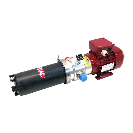
3 | Filter unit/filter housing over-view HYDAC FILTER SYSTEMS GMBH 3 Filter unit/filter housing over-view The filter units of the OLF-5 and OLF-10 series are used for the fine filtration of hydraulic oils in bypass flow. The series has many versions e.g. with or without the motor-pump unit, ele-... -
Page 21: Proper/Designated Use
HYDAC FILTER SYSTEMS GMBH Filter unit/filter housing over-view | 3 3.1 Proper/designated use Use the filter/filter unit only for the application described in the following: The filter/filter unit is designed for the fine filtration of lubricat- ing and hydraulic oils in bypass flow. -
Page 22: Improper Use Or Use Deviating From Intended Use
3 | Filter unit/filter housing over-view HYDAC FILTER SYSTEMS GMBH 3.2 Improper use or use deviating from intended use DANGER Danger due to unintended use Bodily injury and damage to property u Never operate the filter unit in potentially explosive atmos- pheres. -
Page 23: Checking The Scope Of Delivery
HYDAC FILTER SYSTEMS GMBH Filter unit/filter housing over-view | 3 3.3 Checking the scope of delivery The filter unit/filter is delivered packed and ready for use. Please check the filter unit for possible damage before com- missioning. Immediately report any damage in transit to the forwarding agent or the HYDAC department in charge. -
Page 24: Decoding The Type Label
3 | Filter unit/filter housing over-view HYDAC FILTER SYSTEMS GMBH 3.4 Decoding the type label For identification details of the filter housing, see the name plate. Fig. 4: Decoding model code Item Description (1) - Filter unit nameplate (2) - Filter unit model code... - Page 25 HYDAC FILTER SYSTEMS GMBH Filter unit/filter housing over-view | 3 Voltage/Grid - Voltage/power supply Frequency - Frequency Current - Current consumption P max - Operating pressure, maximum Flow rate - Flow rate Weight - Empty weight MoWa OLF-5 3433222d en-us print...
-
Page 26: Model Code
3 | Filter unit/filter housing over-view HYDAC FILTER SYSTEMS GMBH 3.4.1 Model code The filter unit/filter housing is defined by the following model code: OLF - 5/xx - S - xxx-x - NxXMxxx - xx Basic Type OLF = OffLine Filter... -
Page 27: Tab. 3 Over-View - Electric Motors, Power/Supply Voltage
HYDAC FILTER SYSTEMS GMBH Filter unit/filter housing over-view | 3 OLF-5 OLF-5/4 OLF-5/15 5 l/min 4 l/min 15 l/min 120-N 120 W, 3x400 V, 50 Hz 120-M 120 W, 1x230 V, 50 Hz 120-K 120 W, 1x120 V, 60 Hz 370-N 370 W, 3x400 V, 50 Hz 370 W, 3x440 V … 480 V, 60 Hz 370-M 370 W, 1x230 V, 50 Hz 370-K 370 W, 1x120 V, 60 Hz... -
Page 28: Tab. 5 Over-View - Filter Elements N10Xmxxx
3 | Filter unit/filter housing over-view HYDAC FILTER SYSTEMS GMBH OLF-10 OLF-10/4 OLF-10/15 5 l/min 4 l/min 15 l/min N10DM001 Dimicron , Filtration rating, 1 µm (absolute) N10DM002 Dimicron, Filtration rating, 2 µm (absolute) N10DM005 Dimicron, Filtration rating, 5 µm (absolute) N10DM010 Dimicron, Filtration rating, 10 µm (absolute) N10DM020 Dimicron, Filtration rating, 20 µm (absolute) -
Page 29: Tab. 6 Overview - Filter Cartridges (Spin-On)
HYDAC FILTER SYSTEMS GMBH Filter unit/filter housing over-view | 3 OLF-5 OLF-5/4 OLF-5/15 5 l/min 4 l/min 15 l/min M180B020 Filter cartridge (Spin-On), Filter rating, 20 µm (absolute) Without filter element/filter cartridge (Spin-On) Tab. 6: Overview – Filter cartridges (Spin-On) – Not for the Toploader version, (X) selection is possible, (-) -
Page 30: Technical Data
3 | Filter unit/filter housing over-view HYDAC FILTER SYSTEMS GMBH 3.5 Technical Data The technical data of the filter unit is as follows: Bypass opening pressure ≈ 3.5 bar for the filter element Permissible fluid contamina- < 12 NAS according to ISO4406 tion Class 23/21/18 Flow rate and OLF-5-…... -
Page 31: Tab. 8 Technical Data
HYDAC FILTER SYSTEMS GMBH Filter unit/filter housing over-view | 3 Emission sound pressure < 70 db(A) level L Design service life If the service and maintenance intervals are followed, the design service life of the unit is not lim- ited. Tab. 8: Technical data *) When the viscosity is high, the flow rate can be significantly lower. -
Page 32: Dimensions / Hydraulic Diagram
3 | Filter unit/filter housing over-view HYDAC FILTER SYSTEMS GMBH 3.6 Dimensions / hydraulic diagram In this chapter, you will find the drawings with the dimensions and the hydraulic diagram of the different versions of the filter units/filter housings. 3.6.1 Drawing OLF-5-S-…... - Page 33 HYDAC FILTER SYSTEMS GMBH Filter unit/filter housing over-view | 3 All dimensions in mm. Item Description Fluid inlet Fluid outlet Draining/draining fluid DRAIN Clogging indicator Required space for removing the filter element Room required for cooling the electric motor MoWa OLF-5 3433222d en-us print...
-
Page 34: Components Olf-5-S
3 | Filter unit/filter housing over-view HYDAC FILTER SYSTEMS GMBH 3.6.1.1 Components OLF-5-S… The filter unit has the following components: Fig. 7: OLF-5-S… components Pos. Description Fluid inlet Fluid outlet Draining/draining fluid DRAIN Clogging indicator Electric motor Ventilator hood Terminal box... -
Page 35: Drawing Olf-5/15-S
HYDAC FILTER SYSTEMS GMBH Filter unit/filter housing over-view | 3 3.6.2 Drawing OLF-5/15-S-… The filtration unit has the following dimensions: Fig. 8: Drawing OLF-5-15-S-xxx-BM… All dimensions in mm. MoWa OLF-5 3433222d en-us print 35 / 100... - Page 36 3 | Filter unit/filter housing over-view HYDAC FILTER SYSTEMS GMBH Item Description Fluid inlet Fluid outlet Draining/draining fluid DRAIN Ventilation / bleeding BLEED Clogging indicator Required space for removing the filter element Room required for cooling the electric motor 36 / 100...
-
Page 37: Olf-5/15-S
HYDAC FILTER SYSTEMS GMBH Filter unit/filter housing over-view | 3 3.6.2.1 OLF-5/15-S…BM components The filter unit has the following components: Fig. 9: OLF-5/15-S…BM components Item Description Fluid inlet Fluid outlet Draining/draining fluid DRAIN Clogging indicator Electric motor Ventilator hood Terminal box... -
Page 38: Drawing Olf-5/4-Sp
3 | Filter unit/filter housing over-view HYDAC FILTER SYSTEMS GMBH 3.6.3 Drawing OLF-5/4-SP… The filtration unit has the following dimensions: Fig. 10: Drawing OLF-5/4-SP All dimensions in mm. 38 / 100 MoWa OLF-5 3433222d en-us print... - Page 39 HYDAC FILTER SYSTEMS GMBH Filter unit/filter housing over-view | 3 Item Description Fluid inlet Fluid outlet Draining/draining fluid DRAIN Clogging indicator Required space for removing the filter element Room required for cooling the electric motor MoWa OLF-5 3433222d en-us print...
-
Page 40: Olf-5/4-Sp
3 | Filter unit/filter housing over-view HYDAC FILTER SYSTEMS GMBH 3.6.3.1 OLF-5/4-SP…component The filter unit has the following components: Fig. 11: OLF-5/4-SP… components Item Description Fluid inlet Fluid outlet Clogging indicator Electric motor Ventilator hood Terminal box Mounting base/electric motor base... -
Page 41: Drawing Olf-5/4-S
HYDAC FILTER SYSTEMS GMBH Filter unit/filter housing over-view | 3 3.6.4 Drawing OLF-5/4-S… All dimensions in mm. Item Description Fluid inlet Fluid outlet Draining/draining fluid DRAIN Clogging indicator Required space for removing the filter element Room required for cooling the electric motor... -
Page 42: Olf-5/4-S
3 | Filter unit/filter housing over-view HYDAC FILTER SYSTEMS GMBH 3.6.4.1 OLF-5/4-S…BM components The filter unit has the following components: Fig. 12: OLF-5/4-S…BM components Item Description Fluid inlet Fluid outlet Draining/draining fluid DRAIN Clogging indicator Electric motor Ventilator hood Terminal box... -
Page 43: Transportation/Storage
HYDAC FILTER SYSTEMS GMBH Transportation/storage | 4 4 Transportation/storage Fully empty the filter unit/filter housing before transporting it or putting it into storage. Remove the used filter element/filter car- tridge and clean the inside of the filter housing. NOTICE Do not grip the filter unit/filter housing at the clogging indicator The clogging indicator will be damaged/destroyed. -
Page 44: Mounting/Installing
5 | Mounting/installing HYDAC FILTER SYSTEMS GMBH 5 Mounting/installing The following provides information on how to install and con- nect the filter unit/filter housing, hydraulically and electrically. 5.1 Fastening/mounting the filter unit The filter unit must be mounted vertically. Fix the filtration unit by means of four suitable screws, with the mounting base or the base on the electric motor, depending on the version. -
Page 45: Fig. 14 Assembly With A Foot On Electric Motor
HYDAC FILTER SYSTEMS GMBH Mounting/installing | 5 Fig. 14: Assembly with a foot on electric motor The dimensions, connections and circuit diagrams for the re- spective version can be found in the "Annex" chapter. If the oil level in the hydraulic system is higher than the filter housing, install additional shut-off devices at the inlet (IN)/outlet (OUT). -
Page 46: Avoiding Siphoning
5 | Mounting/installing HYDAC FILTER SYSTEMS GMBH 5.2 Avoiding siphoning If there is a height difference ΔH between the suction side and pressure side container side / system, the low lying line can develop a suction effect and trigger the siphoning effect be- tween the communicating containers / systems. - Page 47 HYDAC FILTER SYSTEMS GMBH Mounting/installing | 5 After the filter unit is switched off, the height difference/pri- mary pressure can cause flow to occur both in the feed direc- tion and against the feed direction and the fluid can leak un- controllably.
-
Page 48: Observing/Calculating Pressure Loss
5 | Mounting/installing HYDAC FILTER SYSTEMS GMBH 5.3 Observing/calculating pressure loss The pressure loss in a hydraulic line depends upon: – Flow – Kinematic viscosity – Pipe dimensions – Fluid density The pressure loss can be estimated as follows for mineral oil- based hydraulic oils: Fig. 16: Pressure loss formula... - Page 49 HYDAC FILTER SYSTEMS GMBH Mounting/installing | 5 – Ensure that the connecting lines (suction side / pressure side) do not transfer any voltage or cause vibrations on the unit. Use hoses or compensators if necessary. MoWa OLF-5 3433222d en-us print...
-
Page 50: Measuring Or Displaying The Back Pressure / Differential Pressure
5 | Mounting/installing HYDAC FILTER SYSTEMS GMBH 5.4 Measuring or displaying the back pressure / differential pressure If pressure measurements are carried out in a hydraulic sys- tem, the type of measurement such as the back pressure or differential pressure and also the measurement point are cru- cial, as shown below. -
Page 51: Connecting The (In) Suction Port
HYDAC FILTER SYSTEMS GMBH Mounting/installing | 5 5.5 Connecting the (IN) suction port Use a connector that is suitable for the port. The size of the connection and the type of the threads can be found in the "Technical data" chapter Note the following when connecting the filter unit: 1. -
Page 52: Connecting The Pressure Port (Out)
5 | Mounting/installing HYDAC FILTER SYSTEMS GMBH 5.6 Connecting the pressure port (OUT) Use a connector that is suitable for the port. The size of the connection and the type of the threads can be found in the "Technical data" chapter... -
Page 53: Check Direction Of Rotation
HYDAC FILTER SYSTEMS GMBH Mounting/installing | 5 Fig. 18: Star-delta connection Star connection Delta connection 5.7.1 Check direction of rotation Check the direction of rotation on the electric motor by switch- ing it on briefly (manual operation). An arrow on the fan shroud / pump shows the correct direction of rotation. -
Page 54: Connecting The Electrical Clogging Indicator
5 | Mounting/installing HYDAC FILTER SYSTEMS GMBH NOTICE Incorrect phase sequence / direction of rotation of the electric motor The pump is damaged / The pump is not working. u Note the direction of rotation marked on the fan shroud / pump. - Page 55 HYDAC FILTER SYSTEMS GMBH Mounting/installing | 5 NOTICE Pressure port / Outlet OUT closed The filter unit/filter housing will be damaged/destroyed u Make sure that the pressure port is always open during operation. OLF-5/4 / OLF-10/4 In case of the filter unit OLF-5/4 / OLF-10/4, observe: If the pump is not pre-filled and has an operating viscosity > 200 mm²/s, then the unit reaches the maximum flow rate of...
-
Page 56: Checking The Installation
5 | Mounting/installing HYDAC FILTER SYSTEMS GMBH 5.10 Checking the installation Check all the electric/hydraulic connections, screwed connec- tions and components for firm seating. After commissioning, check all the functions and for leaks. 56 / 100 MoWa OLF-5 3433222d en-us print... -
Page 57: Operation
HYDAC FILTER SYSTEMS GMBH Operation | 6 6 Operation To monitor the service life of the filter element/filter cartridge during operation, the filter unit/filter housing is fitted with a clogging indicator (back pressure/differential pressure, optical or electric). Visually check the optical clogging indicator daily. See chapter Observing the optical clogging indicator (optional) [} 57]... -
Page 58: Rectifying Malfunctions
7 | Rectifying malfunctions HYDAC FILTER SYSTEMS GMBH 7 Rectifying malfunctions The following errors may occur during handling or operation of the filter unit/filter housing: Malfunction Cause(s) Rectification No flow The unit pumps Make sure that in the incorrect the pump pumps flow direction. -
Page 59: Tab. 9 Error/Cause/Rectification
HYDAC FILTER SYSTEMS GMBH Rectifying malfunctions | 7 Malfunction Cause(s) Rectification the circulation of the fluid within the pump (pres- sure relief valve opened) and normal pump op- eration has then started. Leakage at the The drain plug at Tighten the nuts... -
Page 60: Performing Maintenance
8 | Performing Maintenance HYDAC FILTER SYSTEMS GMBH 8 Performing Maintenance In this chapter, you will find the description of the required maintenance activities and the qualifications of the staff needed to carry out these tasks. WARNING The hydraulic system is under operating pressure... -
Page 61: Maintenance Table
HYDAC FILTER SYSTEMS GMBH Performing Maintenance | 8 See also 2 Changing the filter cartridge - Spin-On [} 70] 8.1 Maintenance table Additional information Observing the op- tical clogging indi- cator (optional) Change the filter element - DIMI- CRON Changing the fil-... -
Page 62: Resetting The Vm X Bm.x Visual Clogging Indicator
8 | Performing Maintenance HYDAC FILTER SYSTEMS GMBH 8.2 Resetting the VM x BM.x visual clogging indicator The VM x BM.x visual clogging indicator has a manual reset. Reset the clogging indicator by hand after every filter element replacement as shown below. Fig. 20: Resetting the VM x BM.x visual clogging indicator Step Description 1. -
Page 63: Change The Filter Element - Dimicron
HYDAC FILTER SYSTEMS GMBH Performing Maintenance | 8 8.3 Change the filter element - DIMICRON The procedure for changing the filter element DIMICRON is given in this chapter. 1x Allen wrench = 5 mm 1x Allen wrench = 6 mm Proceed as follows for changing the DIMICRON filter element: 1. - Page 64 8 | Performing Maintenance HYDAC FILTER SYSTEMS GMBH 3. Loosen the housing clamps (1) on the filter housing and remove them in a downwards direction (2). Use an Allen key ( = 5 mm) (1). 4. Pull the filter bowl including filter element downwards.
- Page 65 HYDAC FILTER SYSTEMS GMBH Performing Maintenance | 8 5. Remove (2) the filter element by lightly turning (1) from the filter bowl. 6. Clean the inside of the filter bowl of dirt and deposits. MoWa OLF-5 3433222d en-us print 65 / 100...
- Page 66 8 | Performing Maintenance HYDAC FILTER SYSTEMS GMBH 7. Check the O-ring on the filter bowl for damage. If required, replace it. Coat the O-rings on the filter bowl lightly with the operat- ing medium. 8. Moisten the O-rings on the new filter element with the operating medium.
- Page 67 HYDAC FILTER SYSTEMS GMBH Performing Maintenance | 8 9. Turning it slightly, press the new filter element down into the mount on the filter bowl. MoWa OLF-5 3433222d en-us print 67 / 100...
- Page 68 8 | Performing Maintenance HYDAC FILTER SYSTEMS GMBH 10. Push the filter bowl with the filter element up into the mount on the filter head. 11. Push the housing clamp (1) from the bottom over the fil- ter bowl to the top over bead on the filter bowl/filter head.
- Page 69 HYDAC FILTER SYSTEMS GMBH Performing Maintenance | 8 O The replacement of the filter element is complete. After commissioning, check the filter unit for leaks. MoWa OLF-5 3433222d en-us print 69 / 100...
-
Page 70: Changing The Filter Cartridge - Spin-On
8 | Performing Maintenance HYDAC FILTER SYSTEMS GMBH 8.4 Changing the filter cartridge - Spin-On The procedure for changing the Spin-On filter cartridge is given in this chapter. 1x strap wrench Proceed as follows for changing the Spin-On filter cartridge: 1. -
Page 71: Fig. 21 Spin-On Filter Cartridge
HYDAC FILTER SYSTEMS GMBH Performing Maintenance | 8 7. For the filter cartridge 0160 MA 0xx BN, remove the old sealing ring (1) to the filter element in the connector head and replace it with the new sealing ring. The sealing ring (2) has already been fitted on the filter cartridge 0160 MG 010 P. -
Page 72: Changing The Filter Element - Toploader
8 | Performing Maintenance HYDAC FILTER SYSTEMS GMBH 8.5 Changing the filter element - Toploader In this chapter, you will find the procedure for changing the fil- ter element. 1x Allen wrench = 5 mm 1x Allen wrench = 6 mm The following steps relate to a Toploader filter unit/filter hous- ing. - Page 73 HYDAC FILTER SYSTEMS GMBH Performing Maintenance | 8 motor. After emptying the housing, screw the drain plug Drain in again. 5. Loosen the housing clamps (1) on the filter housing with an Allen wrench ( = 5 mm). Remove the screw head (2) and take the housing clamp off to the top (3).
- Page 74 8 | Performing Maintenance HYDAC FILTER SYSTEMS GMBH 8. Remove the filter element from the filter bowl cover by rotating it clockwise by 90° and dispose of it in an envi- ronmentally friendly manner. 9. Clean the inside of the filter housing of dirt and deposits.
- Page 75 HYDAC FILTER SYSTEMS GMBH Performing Maintenance | 8 13. Place the filter element with the filter bowl cover and the dirt catch tray in the filter housing. Check the O-ring on the cover for being seated cor- rectly. 14. Place the tensioning clamp around the filter housing and filter lid (1).
-
Page 76: A Appendix
A | Appendix HYDAC FILTER SYSTEMS GMBH A Appendix A.1 Finding spare parts/accessories Use only original spare parts for a long and defect-free life cy- cle of the product. When ordering spare parts and accessories make sure to always indicate the exact model code and the se- rial number. - Page 77 HYDAC FILTER SYSTEMS GMBH Appendix | A Item Designation Part no. 2.11 Repair kit OLF-5/4, consisting of: 3052460 vane pump, - 6x O-ring, - 4x screws 2.11 Repair kit OLF-5/4, consisting of: 3075885 vane pump, - 6x O-ring, - 4x screws 2.11 Repair kit OLF-5/15, consisting of:...
- Page 78 A | Appendix HYDAC FILTER SYSTEMS GMBH Item Designation Part no. 4.00 Filter element 10 µm N10DM010 3539238 DIMICRON 4.00 Filter element 20 µm N5DM020 3023508 DIMICRON 4.00 Filter element 20 µm N10DM020 3539242 DIMICRON 4.00 Filter element 2 µm N5AM002 349677 AQUAMICRON 4.00 Filter element 2 µm...
- Page 79 HYDAC FILTER SYSTEMS GMBH Appendix | A Item Designation Part no. 4.01 Spin-On / Filter cartridge 10 µm, 0160 MG 010 P 249005 paper Empty cartridge for circulation pump- 0160 MA 300082 Item Designation Part no. HYDAC label 625925 "Direction of rotation of electric motor"...
-
Page 80: Spare Parts - Toploader T / Tv
A | Appendix HYDAC FILTER SYSTEMS GMBH A.1.1 Spare parts - Toploader T / TV The following spare parts are available for the Toploader T / TV version: Item Qty Designation Part no. 1.11 1 Drain screw with seal ring G1/4 617095 1.11 1... -
Page 81: Drawing Of Spare Part Olf-5
HYDAC FILTER SYSTEMS GMBH Appendix | A A.1.2 Drawing of spare part OLF-5... The following drawing shows the spare parts of the OLF-5…: Fig. 22: Spare parts OLF-5-S-... 1204630 MoWa OLF-5 3433222d en-us print 81 / 100... -
Page 82: Drawing Of Spare Part Olf-5/4
A | Appendix HYDAC FILTER SYSTEMS GMBH A.1.3 Drawing of spare part OLF-5/4... The following drawing shows the spare parts of OLF-5/4…: Fig. 23: Spare parts OLF-5/4 - 3041370 82 / 100 MoWa OLF-5 3433222d en-us print... -
Page 83: Drawing Of Spare Part Olf-5/Xx-T
HYDAC FILTER SYSTEMS GMBH Appendix | A A.1.4 Drawing of spare part OLF-5/xx-T-... Toploader The following drawing shows the spare parts of OLF-5/xx-T-…: Fig. 24: Spare parts OLF-5/xx-T - 3244069 MoWa OLF-5 3433222d en-us print 83 / 100... -
Page 84: Accessories - Tank Connection Kit Olf-5-Tak
A | Appendix HYDAC FILTER SYSTEMS GMBH A.1.5 Accessories - Tank Connection Kit OLF-5-TAK The Tank Connection Kit TAK is designed for the easy and quick retrofitting on an OLF filter unit on existing hydraulic sys- tems. This can be used on all hydraulic systems with a breather filter according to the connection diagram DIN 24557/... -
Page 85: Contacting Customer Service
HYDAC FILTER SYSTEMS GMBH Appendix | A A.2 Contacting Customer Service Contact data such as the telephone numbers, e-mail and mail- ing addresses for the Hotline, product support, , , service part- ners for maintenance, repair and spare parts can be found, al- ways updated, on our homepagewww.hydac.com. -
Page 86: Clogging Indicators - Technical Data
A | Appendix HYDAC FILTER SYSTEMS GMBH A.3 Clogging indicators - technical data Listed below are the technical data pertaining to the optional, optical or electrical clogging indicators suitable for the installa- tion in the filter housing / filter unit. -
Page 87: Tab. 13: Differential Pressure Indicator -Visual Vm X B.x
HYDAC FILTER SYSTEMS GMBH Appendix | A Permissible operating over- ≤ 210 bar pressure Permitted temperature range -30 … +100°C Connector threads G ½ Installation space required According to HN 28-22 Maximum tightening torque 33 Nm Tab. 13: Differential pressure indicator -visual VM x B.x MoWa OLF-5 3433222d en-us print... -
Page 88: Differential Pressure Indicator, Visual - Vm X Bm.x
A | Appendix HYDAC FILTER SYSTEMS GMBH A.3.2 Differential pressure indicator, visual – VM x BM.x The optical differential pressure gauge reacts to the increasing pressure difference at the increasing contamination level of the filter element. 88 / 100 MoWa OLF-5 3433222d en-us print... -
Page 89: Differential Pressure Gauge, Electric (Vm X C.x)
HYDAC FILTER SYSTEMS GMBH Appendix | A A.3.3 Differential pressure gauge, electric (VM x C.x) The electric clogging indicator reacts to the increasing pres- sure difference at the increasing contamination level of the fil- ter element. Fig. 27: Differential pressure indicator, electrical VM x C.x... -
Page 90: Tab. 14: Differential Pressure Indicator, Electrical Vm X C.x
A | Appendix HYDAC FILTER SYSTEMS GMBH Response pressure and indi- VM 2 C.x = 2 bar -10% cation range respectively VM 3 C.x = 3 bar -10% VM 5 C.x = 5 bar -10% Permissible operating over- ≤ 210 bar pressure Permitted temperature range -30 … +100°C Connector threads G ½ Installation space required According to HN 28-22 Maximum tightening torque 33 Nm... -
Page 91: Differential Pressure Gauge, Electric (Vm X D.x /-L-Xx)
HYDAC FILTER SYSTEMS GMBH Appendix | A A.3.4 Differential pressure gauge, electric (VM x D.x /-L- The electric clogging indicator reacts to the increasing pres- sure difference at the increasing contamination level of the fil- ter element. Fig. 28: Differential pressure indicator, electrical VM x D.x /-Lxx... -
Page 92: Tab. 15 Differential Pressure Indicator, Electrical Vm X D.x / -Lxx
A | Appendix HYDAC FILTER SYSTEMS GMBH Response pressure and indi- VM 2 D.x = 2 bar -10% cation range respectively VM 3 D.x = 3 bar -10% VM 5 D.x = 5 bar -10% Permissible operating over- ≤ 210 bar pressure Permitted temperature range -30 … +100°C Connector threads G ½ Installation space required According to HN 28-22 Maximum tightening torque 33 Nm... - Page 93 HYDAC FILTER SYSTEMS GMBH Table of Illustrations Table of Illustrations Overview / labeling of the title page ............Fig. 1 Fire protection class B ................Fig. 2 Minimum distance for fire fighting............. Fig. 3 Decoding model code................Fig. 4 Model Code ....................
- Page 94 Table of Illustrations HYDAC FILTER SYSTEMS GMBH OLF-5 TAK ....................Fig. 25 Differential pressure indicator - visual VM x B.x ........Fig. 26 Differential pressure indicator, electrical VM x C.x ........Fig. 27 Differential pressure indicator, electrical VM x D.x /-Lxx ......Fig. 28 94 / 100 MoWa OLF-5 3433222d en-us print...
- Page 95 HYDAC FILTER SYSTEMS GMBH Index of Tables Index of Tables Tab. 1 Target group ..................... Tab. 2 Scope of delivery ..................Tab. 3 Over-view - Electric motors, power/supply voltage ........Tab. 4 Over-view – Filter elements N5xMxxx ............Tab. 5 Over-view –...
-
Page 96: Glossary
Glossary HYDAC FILTER SYSTEMS GMBH Glossary cording to ASTM D 1418) repre- AQUAMICRON sents an entire group of rubbers, The filter elements of the AQUAMI- which have, as a common charac- CRON series are characterized by teristic, viniledine difluoride as one their high dust holding capacity of of its monomers. - Page 97 HYDAC FILTER SYSTEMS GMBH Glossary Toploader Nitrile Butadiene Rubber, abbrevia- tion NBR, is a copolymer made of acrylonitrile and 1,3 butadiene and is a synthetic rubber. Vulcanates of the rubber have a figh resistance against mineral oils, greases and hydrocarbons. (Source: Wikipedia)
-
Page 98: Index
Index HYDAC FILTER SYSTEMS GMBH Index Back pressure vs. Differential pressure exclusion of liability 12 50 Branches 85 Hotline 85 HYDAC Service calculating pressure loss 48 Germany 85 Clogging indicator Worldwide 85 Differential pressure indicator 87, 90, 92 Connecting electrically Imprint 2... - Page 99 HYDAC FILTER SYSTEMS GMBH Index Terms and Conditions 12 Terms of Delivery 12 Warranty 12 MoWa OLF-5 3433222d en-us print 99 / 100...
- Page 100 www.hydac.com...
Need help?
Do you have a question about the OLF-5 Series and is the answer not in the manual?
Questions and answers