Table of Contents
Advertisement
Quick Links
Advertisement
Table of Contents

Related Manuals for Leutert DPI


Summary of Contents for Leutert DPI
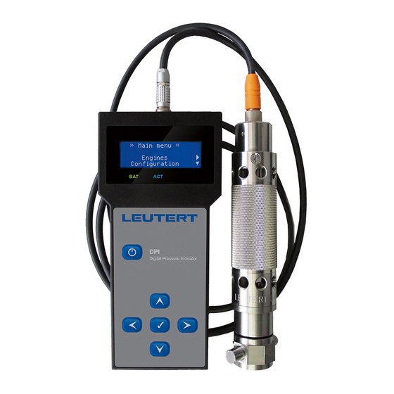
- Page 1 Digital Pressure Indicator DPI Operating Instructions Cylinder pressure monitoring The DPI Digital Pressure Indicator measures dynamic pressures. It is designed to analyze the internal combustion curve of large two and four stroke diesel engines. The measurement is performed via an...
-
Page 2: Table Of Contents
Technical data ..............8 Software ..................9 2.4.1 Description ..............9 2.4.2 Requirements for the PC ..........9 Prepare the DPI system for use ............10 Software installation ............... 10 Prepare the handheld device for the measurement ....12 3.2.1 Enter motor parameters ..........12 3.2.2 Transfer motor parameters to the handheld device .. - Page 3 Digital Pressure Indicator DPI - Bedienungsanleitung General The operating instructions serve to ensure that the product is used properly, effectively and safely. Please read all instructions and warnings carefully. Follow all safety precautions to avoid personal injury or property damage during the workflow.
-
Page 4: Safety Instructions
Digital Pressure Indicator DPI - Bedienungsanleitung Safety instructions The DPI may only be operated by trained personnel with the utmost cau- tion and in compliance with the safety regulations for measuring large die- sel and gas engines. DANGER Wear protective glasses during the measurement as hot gas or par- ticles come out of the engine and could injure you. -
Page 5: Product Description
DPI range and replaces all mechanical indicators. In order to be able to measure pressure profiles with the DPI each cylinder of the engine must be equipped with a standard indicator valve. By means of the Thompson adapter the DPI pressure sensor is temporarily mounted to the corresponding indicator valve. -
Page 6: Handheld Device
All representations and mathematical calculations in the DPI software are based on this data. The saved measurement data can be transferred to a PC / laptop by the DPI software to be visualized, evaluated or to be sent electronically. The measurement data evaluation using Windows-based software gives the ability to make complex diagnostic statements about the quality of the combustion processes. -
Page 7: Technical Data
Digital Pressure Indicator DPI - Bedienungsanleitung Shoulder strap Battery compartment for 4 x 1.5 V batteries Type label with CE marking Plastic housing 2.2.2 Technical data Storage capacity 50 engines with up to 24 cylinders each Interface USB 2.0 Power supply rechargeable standard AA NiMH batteries 1.2 V / 2000 mAh... -
Page 8: Pressure Sensor
Digital Pressure Indicator DPI - Bedienungsanleitung Pressure sensor 2.3.1 Design The DPI is supplied with a pressure sensor and connection cable. By the armored cable with plug the sensor is connected with the DPI hand-held device. The pressure sensor is suitable for temporary measurements on indicator valves only (gas pressure measurements on internal combustion engines). -
Page 9: Software
2.4.1 Description After measuring the engine the measuring values saved in the handheld device are transferred to the PC and can be displayed with the DPI soft- ware and evaluated in detail. To analyze the engine data different visu- alization modes are available (pressure diagram, PV diagram, bar graphs, tabular information). -
Page 10: Requirements For The Pc
Link to the manufacturer’s homepage 2.4.2 Requirements for the PC In order to be able to run the DPI software, your PC should meet the fol- lowing requirements: – A free USB port for data transfer between the handheld device –... -
Page 11: Software Installation
The software is stored in the handheld device’s memory upon delivery and must be copied and installed on the PC before use. Connect the DPI handheld device with a Windows PC using the sup- plied USB cable. The DPI automatically turns on and is recognized by the computer as a drive. - Page 12 Windows start menu and Desktop icon for the DPI software. If a previous version of the DPI software is already set up on your PC, you can update it. You will receive updates e.g. electronically..
-
Page 13: Prepare The Handheld Device For The Measurement
At fi rst use of the device you have to enter the engine parameters once for each engine. NOTICE Pay attention to correct entries so that the DPI gives you correct measurement results. Start the DPI software on the PC. Open the command [Open Data- base] in the menu [File]. - Page 14 The DPI is able to measure the TDC based on the pressure curve showing the course of combustion. This is the basis of the power calculation.
- Page 15 Connect the handheld device to the PC by means of the USB ca- ble. The handheld device switches on automatically and the battery charging process begins. A green LED symbol in the status bar of the DPI software indicates that the handheld device is connected to the PC. NOTICE If the handheld device is connected to the PC or the battery charger via USB button operation is not possible.
- Page 16 Digital Pressure Indicator DPI - Bedienungsanleitung Mark the desired engine and click on [To Handheld]. After success- fully transferring the engine parameters to the connected hand-held device the new engine appears in the list. The handheld device is now ready for the measurement.
-
Page 17: Set Date And Time Of The Handheld Device
The date format is month / day / year, the time is displayed in hours:Minutes:seconds. The date / time setting of the handheld device is done in the DPI software by synchronization with the PC settings, provided the PC is set up correctly. - Page 18 Put on protective gloves before indicating because the surface tem- perature of the indicator valve and the sensor can get very high during the indication process. Do not operate the DPI handheld device and the pressure sensor above the allowed pressure and temperature ranges. NOTICE Ensure that the load and the speed is as constant as possible during the measurement in order to get comparable results.
- Page 19 Ti m e l ef t : 0 0 : 4 8 menu. C a n c el NOTICE: Do not turn off the DPI before the measurement is terminated otherwise you would have to wait for the pres- sure sensor to warm up again before each measurement.
- Page 20 Digital Pressure Indicator DPI - Bedienungsanleitung The number of measuring cycles can be adjusted with the arrow M e a s u r e e n gi n e keys . Confi rm the value by A U X E n gi n e 1...
- Page 21 The handheld device must be switched on again for further opera- tions and the last edited menu must be called up again. Unplug the sensor cable from the DPI handheld device. The connection will be detached by pulling the knurled collar away from the handheld device, it should not be unscrewed.
-
Page 22: Display Measurement Results
Transferring data from the handheld device to the PC For analysis and interpretation of the recorded cylinder pressure curve use the DPI software belonging to the system. For this purpose it is necessary to transfer the saved measurement data from the DPI handheld device to the PC. - Page 23 Select the measurement to be imported by clicking on the Check- box. The following options are activated: [Import measurements] imports the data set into the DPI software. If the checkbox (Delete measurements from handheld after import] is marked with a cross the data set will be automatically deleted from the handheld device.
- Page 24 Digital Pressure Indicator DPI - Bedienungsanleitung Click on [Import measurement]. The ’Select ship’ window appears. Select the target directory into which the data record is to be im- ported and confirm with [OK]. The following message shows how many cylinder measurements are included in the imported data set.
-
Page 25: Analyzing Measurement Data With The Dpi Software
Various display modes are available for analyzing the measured values which are described in the following sections. Start the DPI software on the PC. Open in the menu (File] the Com- mand [Open Database]. Mark the data set to be opened in the list and click on OK]. -
Page 26: Pressure Plot
Digital Pressure Indicator DPI - Bedienungsanleitung 5.2.1 Pressure Plot The curve progression shown in the [Pressure Plot] display mode shows the cylinder pressure [bar] for each cylinder measured at the indicator valve depending on the crankshaft angle [° CA]. Select from the right window area the cylinders to be displayed: –... - Page 27 Digital Pressure Indicator DPI - Bedienungsanleitung In the left window the following display options are available: – Multiple cylinder: selection of all cylinders – All cycles: display of all measured cycles of a cylinder – Min / max cycles: shows the minimum and the maximum cycle of a cylinder –...
- Page 28 Digital Pressure Indicator DPI - Bedienungsanleitung Some important pressure values to be read from the cylinder pressure curve are plotted in the graphic above. Peak pressure Shows the maximum pressure value of the measurement curve, also known as ignition pressure.
- Page 29 Digital Pressure Indicator DPI - Bedienungsanleitung [Pressure plot] shows the cylinder pressure at the respective indicator valve depending on the crankshaft angle, at the top with activated first deriva- tive. Axis for the cylinder pressure, scaling in bar This axis is automatically adjusted to the max. cylinder pressure of the current measurement.
-
Page 30: Tdc Correction
Digital Pressure Indicator DPI - Bedienungsanleitung 5.2.2 TDC Correction In the display mode [TDC Correction] the position of the top dead center can be determined which is necessary for the performance calculation. The cylinder to be displayed is selected in the right window are. - Page 31 Digital Pressure Indicator DPI - Bedienungsanleitung Optionally the TDC can also be determined using software or it can be determined manually. To correct the top dead center TDC there are various opportunities under „Correction:“: – [Auto All Cyl.] – [AutoCorr.Cyl.01] –...
-
Page 32: Pv Plot
Digital Pressure Indicator DPI - Bedienungsanleitung 5.2.3 PV Plot The display mode [PV Plot] illustrates the cylinder pressure in relation to the volume curve. The cylinders to be displayed are selected in the right window area. Available buttons: Toggle Crosshair - switch on / off horizontal line for reading the pressure values... - Page 33 Digital Pressure Indicator DPI - Bedienungsanleitung The PV diagram [PV Plot] shows the course of the cylinder pressure bet- ween top dead center (TDC) and bottom dead center (BDC) during a wor- king cycle. Axis for the pressure in bar axis for volume change from BDC to TDC The inner area represents the “gain of work”.
-
Page 34: Bar Graph
Digital Pressure Indicator DPI - Bedienungsanleitung 5.2.4 Bar Graph In the [Bar Graph] mode the selected measurement data is displayed in form of a bar graph. This view allows you to easily compare the individual cylinders with each other. The bar chart below shows a sample data set that shows the maximum of the combustion pressures for all cylinders with automatic scaling. - Page 35 Digital Pressure Indicator DPI - Bedienungsanleitung Available buttons: Toggle Grid - switch grid on / off Export to pdf - open the current view for printing or saving as a pdf file Toggle Crosshair - switch on / off horizontal line for reading the pressure values...
-
Page 36: Data Info
The table [Data Info] shows the measuring data determined for each cylin- der in numerical order. All presentations and mathematical calculations of the DPI software are based on these measurements. – Date, Time: Date and time of the measurement – Average cycles: number of measured cycles (number of averages) –... -
Page 37: Raw Data
Digital Pressure Indicator DPI - Bedienungsanleitung Available buttons: Export to Excel - Save and open the DataInfo table as an Excel file Export to pdf - open the current view for printing or saving as a pdf file 5.2.6 Raw Data... - Page 38 You start this function in the DPI software with the menu command [File] and [Export to file / email]. If you want to send the data record which is currently opened in the DPI software, this is already marked in the list. Otherwise select the record which you would like to send by email in the window above.
- Page 39 Digital Pressure Indicator DPI - Bedienungsanleitung Friedrich Leutert GmbH & Co. KG...
-
Page 40: Organize Measurement Data In The Handheld Device
Organize measurement data in the handheld device View data records on the handheld device While the measured value is being recorded you can see on the DPI display some of the determined data such as speed, peak and differential pressure. -
Page 41: Delete Data Records In The Handheld Device
Digital Pressure Indicator DPI - Bedienungsanleitung 6.2 Delete data records in the handheld device During the measurement, the DPI saves the measured values as data re- cords which can be assigned to each individual cylinder. If you start a new measurement, this data is overwritten. -
Page 42: Maintenance
Maintenance Maintenance of the pressure sensor The DPI handheld device requires little maintenance. Make sure that the device and the associated pressure sensor is returned to the manufacturer after approx. 100 operating hours or after 3 years to check the calibration data. - Page 43 Digital Pressure Indicator DPI - Bedienungsanleitung Any remaining cleaning agent may be removed with clear water by repeating steps 3 and 4. If the sensor is heavily stained repeat the cleaning procedure. 7.3 Charge the batteries of the handheld device...
-
Page 44: Changing Batteries
Make sure that you have already downloaded and saved the mea- surement data to the PC or that you no longer need the data. If the battery is to be replaced or removed from the DPI, please proceed as follows: Use a fl at-blade screwdriver to screw off the cover of the battery compartment. - Page 45 Digital Pressure Indicator DPI - Bedienungsanleitung Adjusting the contrast and the backlight of the handheld device. Press the button for approx. 1 second to switch on the handheld » M ai n m e n u « device. The main menu appears after the start screen. Use the but-...
- Page 46 This document including all of its parts is protected by copyright. Any du- plication or utilization outside of the copyright law is not permitted wi- thout explicit permission from Friedrich Leutert GmbH & Co. KG and may be subject to prosecution. This applies in particular to duplications of any kind, translations and incorporation into electronic systems.
Need help?
Do you have a question about the DPI and is the answer not in the manual?
Questions and answers