Advertisement
Quick Links
Advertisement

Related Manuals for Diamondback 1260sc Studio Cycle


Summary of Contents for Diamondback 1260sc Studio Cycle
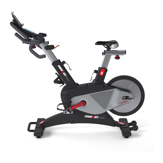
- Page 1 1260Sc Studio Cycle Owners Manual...
- Page 2 Although current at the time of this printing, specifications for this model may have changed in our continuing effort for improvement. Diamondback Fitness reserves the right to modify and improve the specifications of its products without prior notice. Diamondback Fitness...
-
Page 3: Safety Instructions And Warnings
Safety Instructions & Warnings • Every piece of Diamondback Fitness equipment Place the unit in an area that will meet minimum clearance requirements: is built for maximum safety and meets or front & sides = 24 inches (61 cm) exceeds all applicable domestic and international rear = 12 inches (30.5 cm) - Page 4 M3: M4 X 16 SCREW H1: M5 X 12 SCREW A44: M6 X 10 SCREW TOOLS: Please don’t use power tools for any part of the assembly. #13 #14 6 MM 5 MM 4 MM 3 MM 2.5 MM #15 #16 Diamondback Fitness...
- Page 5 Attach the Front and Rear Stabilizers s l o : s t A : Main Frame B4 : M10x55 Screw B : Front Stabilizer B5 : M10 Washer C : Rear Stabilizer Attach the rear stabilizer (C) onto the main frame (A) using screws (B4) and washers (B5) as shown.
- Page 6 Sliding the handlebars (E) to the front and install the screw(A44) into the second hole position. Install the plastic end cap ( A45) to the end of the slide assembly as shown. Finally, tighten the adjustment knob from the first step to finish the assembly. Diamondback Fitness...
- Page 7 Attach the Console Tools: 5 mm hex key Parts: D : Console Tube A44 : M6x10 Screw L : Console L8 : End Cap Attach the console tube ( D) using 2 screws (A44). Tighten one screw into the first hole position and move onto the second screw.
- Page 8 Attach the bottle holder to the main frame (A). Locate the 2 screws (H1) in water bottle holder bag. Use the provided 2.5 mm hex key and firmly tighten the screws to the holes in the main frame as shown. Diamondback Fitness...
- Page 9 Attach the Saddle and Pedals Tools: #13 #14 #15 #17 Parts: G : Saddle K2 : Right Pedal K1 : Left Pedal Attach the saddle. Slide the saddle down onto the seat post and tighten the nuts on both sides equally until firmly secure using the provided tool.
- Page 10 Move the lever lever. Pull up to release the up to increase the lever, make the adjustments resistance. Press the and firmly press the lever lever down to decrease down to secure. the resistance. Diamondback Fitness...
-
Page 11: Troubleshooting
Positioning a small spray bottle and towel near not being tracked accurately. the unit will help ensure that your Diamondback Fitness equipment looks new for many years. 1. Make sure the resistance lever is at the lowest position. - Page 12 Improper assembly the same duration as the express warranty can be avoided if the unit is assembled by herein. Diamondback Fitness shall not be liable an authorized technician. Damage due to for any incidental or consequential damages.
- Page 16 For the most up to date info about using your console and our latest support videos, please visit www.diamondbackfitness.com If you have any questions please contact our support team at support@diamondbackfitness.com.
Need help?
Do you have a question about the 1260sc Studio Cycle and is the answer not in the manual?
Questions and answers