Table of Contents
Advertisement
Advertisement
Table of Contents

Related Manuals for Yardworks 100666


Summary of Contents for Yardworks 100666
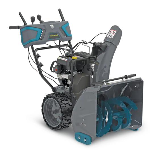
- Page 1 Snowblower model number 060-1314-4 | contact us: 1.866.523.5218 IMPORTANT: Please read this manual carefully before operating this snowblower and save it for reference. WARNING: Machine is without engine oil. Properly fill engine oil prior to use to prevent engine damage.
- Page 2 TAble Of CONTeNTS model no. | contact us: 1.866.523.5218 060-1314-4 SAFETY INSTRUCTIONS SAFETY SYMBOLS OPERATION SYMBOLS SPECIFICATIONS ASSEMBLY OPERATION STARTING THE ENGINE CONTROLS MAINTENANCE FIG. A – SNOWBLOWER PARTS DIAGRAM FIG. A – PARTS LIST – SNOWBLOWER FIG. B – ENGINE DIAGRAM FIG.
- Page 3 model no. | contact us: 1.866.523.5218 060-1314-4 SAfeTy DefINITIONS allow adults to operate the equipment without proper instruction. The purpose of safety symbols is to attract your attention to possible dangers. The Thrown objects can cause serious – safety symbols, and their explanations, injury.
- Page 4 model no. | contact us: 1.866.523.5218 060-1314-4 Let engine and machine adjust to Do not over fill fuel tank. Keep fuel – – outdoor temperatures before starting to level at least ½" (1.27 cm) below clear snow. bottom of filler neck to provide space for fuel expansion.
- Page 5 model no. | contact us: 1.866.523.5218 060-1314-4 OPeRATION Do not clear snow across the face of – slopes. Exercise extreme caution when Do not put hands or feet near or – changing direction on slopes. Do not under rotating parts. Keep clear of the attempt to clear steep slopes.
- Page 6 model no. model no. | contact us: 1.866.523.5218 | contact us: 1.866.523.5218 060-1314-4 060-1314-4 Replace worn or damaged parts for To clear the chute: – safety. Use only genuine replacement SHUT THE ENGINE OFF! – parts and accessories. Wait 10 seconds to be sure the –...
- Page 7 model no. | contact us: 1.866.523.5218 060-1314-4 Some of the following symbols may be used on this product. Please study them and learn their meaning. Proper interpretation of these symbols will allow you to more safely operate the product. Symbol Meaning Read Operator’s Manual.
- Page 8 model no. model no. | contact us: 1.866.523.5218 | contact us: 1.866.523.5218 060-1314-4 060-1314-4 Symbol Meaning Thrown Objects. This machine may pick up and throw objects which can cause serious personal injury. Always Use Chute Tool. Never use your hands to clear a clogged chute assembly.
- Page 9 OPeRATION SyMbOlS model no. | contact us: 1.866.523.5218 060-1314-4 Some of the following symbols may be used on this product. Please study them and learn their meaning. Proper interpretation of these symbols will allow you to more safely operate the product. Symbol Meaning engine Start.
- Page 10 model no. model no. | contact us: 1.866.523.5218 | contact us: 1.866.523.5218 060-1314-4 060-1314-4 Symbol Meaning Cold Prime. To start a cold engine, prime 3-5 times. Warm Prime. To start a warm engine, DO NOT prime. Recoil Start. Pull the recoil starter grip to start manually. Choke: Off.
- Page 11 model no. | contact us: 1.866.523.5218 060-1314-4 SNOWblOWeR Stages Speed Control 6 forward/2 reverse Clearing Width 24" (61 cm) Clearing Depth 23" (58.4 cm) Impeller Diameter 12" (30.5 cm) Wheel Diameter 15" (38 cm) 14" (35.6 cm) Auger Diameter eNGINe brand Champion Power Equipment Displacement...
- Page 12 model no. | contact us: 1.866.523.5218 060-1314-4 SNOWblOWeR eNGINe A. Discharge Chute Rotation Lever A. Key (Safety Lock Out) B. Auger Control Lever B. Primer Bulb C. Speed Control Lever C. Throttle Lever D. Shear Pin Storage D. Choke Lever E.
- Page 13 model no. | contact us: 1.866.523.5218 060-1314-4...
- Page 14 ASSeMbly model no. model no. | contact us: 1.866.523.5218 | contact us: 1.866.523.5218 060-1314-4 060-1314-4 UNPACKING 1. Set the shipping carton on a solid, flat surface. 2. Remove everything loose from the carton. 3. Cut down the bottom carton to allow a flat surface area to install the assembly parts without scratching parts or cutting tires.
- Page 15 model no. | contact us: 1.866.523.5218 060-1314-4 HANDle 1. Attach the lower handle (1-1) onto the unit body with 4 self-tapping bolts (1-2) using included tool or your own 13mm wrench (Fig. 1). Figure 1 2. Connect the upper and lower handle with bolts (2-1), washers (2-2) and locking knobs (2-3) (Fig.
- Page 16 model no. | contact us: 1.866.523.5218 060-1314-4 4. Put the snow discharge chute cable wire form on the snow discharge support using the washer (4-1) and nut (4-2). Securely tighten the assembly (Fig. 4) using included tool or your own 16mm wrench.
- Page 17 model no. | contact us: 1.866.523.5218 060-1314-4 CHeCK/ADD eNGINe OIl Recommended Engine Oil Type Capacity of engine oil: 16.9 fl. oz. (0.5 l) Use 0W-30, but in some cases, depending 0W-30 5W-30 on weather, 5W-30 will work. See chart for oil type recommendations.
- Page 18 model no. | contact us: 1.866.523.5218 060-1314-4 ADD fUel fuel tank capacity: 88 fl. oz. (2.6 l) Use clean, fresh, regular unleaded gasoline with a minimum octane rating of 85 and an ethanol content of less than 10% by volume. SAfe HANDlING Of GASOlINe To avoid severe injury or property damage use high levels of care while handling gasoline.
- Page 19 model no. | contact us: 1.866.523.5218 060-1314-4 9. Never store the machine or fuel container inside where there is an open flame, spark or pilot light (e.g., furnace, water heater, space heater, clothes dryer etc.). 10. Allow machine to cool at least 5 minutes before storing. 11.
- Page 20 OPeRATION model no. model no. | contact us: 1.866.523.5218 | contact us: 1.866.523.5218 060-1314-4 060-1314-4 GeNeRAl SAfeTy 1. Read the operating and service instruction manual carefully. Be thoroughly familiar with the controls and the proper use of the equipment. Know how to stop the unit and disengage the controls quickly.
- Page 21 model no. | contact us: 1.866.523.5218 060-1314-4 OPeRATION 1. Do not put hands or feet near or under rotating parts. Keep clear of the discharge opening at all times. 2. Exercise extreme caution when operating on or crossing gravel drives, walks, or roads. Stay alert for hidden hazards or traffic.
- Page 22 model no. | contact us: 1.866.523.5218 060-1314-4 18. Take all possible precautions when leaving the machine unattended. Stop the engine and remove the safety key. 19. Keep all nuts, bolts and screws tight to be sure the equipment is in safe working condition.
- Page 23 model no. | contact us: 1.866.523.5218 060-1314-4 befORe OPeRATION CHeCK THe GeNeRAl CONDITION: Look around and underneath the engine for signs of oil or gasoline leaks. – Remove any excessive dirt or debris, especially around the muffler and recoil starter. –...
- Page 24 STARTING THe eNGINe model no. model no. | contact us: 1.866.523.5218 | contact us: 1.866.523.5218 060-1314-4 060-1314-4 1. Make sure the engine key (safety lock out) is inserted into the keyhole. 2. To start a cold engine: (Fig. 10). 2a. Move the throttle lever (10-1) to full speed.
- Page 25 model no. | contact us: 1.866.523.5218 060-1314-4 4. Stand back and to the right of the unit, pull the starter grip lightly until you feel resistance then pull briskly. Return the starter grip gently (Fig. 12). Figure 12 5. Alternatively, for electric start, plug in the supplied electrical cord into the starter.
- Page 26 model no. model no. | contact us: 1.866.523.5218 | contact us: 1.866.523.5218 060-1314-4 060-1314-4 OPeRATION AT HIGH AlTITUDe The density of air at high altitude is lower than at sea level. Engine power is reduced as the air mass and air-fuel ratio decrease. Engine power will be reduced approximately 3 ½% for every 1000' (304 m) of elevation above sea level.
- Page 27 CONTROlS model no. | contact us: 1.866.523.5218 060-1314-4 Self-DRIVe CONTROl leVeR. Located on the left-side (from behind the snowblower). When the snowblower has been put into gear, pushing this lever towards the handle engages the wheels. Releasing the self-drive control lever causes the machine to stop moving. SPeeD CONTROl leVeR.
- Page 28 model no. | contact us: 1.866.523.5218 060-1314-4 AUGeR CONTROl leVeR. Located on the right side (from behind the snowblower). Pushing this lever towards the handle causes the auger and impeller to activate. Releasing the auger control lever causes the auger to stop moving. Discharge chute deflector lever controls the deflector up or down.
- Page 29 model no. | contact us: 1.866.523.5218 060-1314-4 ADJUSTING THe Self-PROPelleD DRIVe SySTeM: 1. Release the self-drive control lever to bring the snowblower to a stop. 2. Move the speed-control lever to the gear (either forward or reverse) that you require. 3.
- Page 30 model no. model no. | contact us: 1.866.523.5218 | contact us: 1.866.523.5218 060-1314-4 060-1314-4 CHANGe DISCHARGe DIReCTION: 1. Move the discharge chute rotation lever either left or right. CHANGe DISCHARGe HeIGHT: 1. Discharge chute deflector lever controls the deflector up or down. ADJUSTING THe SNOW SHOeS Tilt the snowblower auger back and place a spacer under the shave plate below the –...
- Page 31 MAINTeNANCe model no. | contact us: 1.866.523.5218 060-1314-4 lUbRICATION No parts inside the gearbox are to be lubricated. All bearings and bushings are permanently lubricated and require no maintenance. Lubricating these parts will only result in the grease getting on to the friction wheel and disc drive plate, which could damage the rubber clad friction wheel.
- Page 32 model no. | contact us: 1.866.523.5218 060-1314-4 ReGUlAR SeRVICe PeRIODS Perform at every indicated month or operating hour interval, whichever comes first. every every 3 every 6 every year Item Service each Use month months or months or or 150 hrs. or 20 hrs.
- Page 33 model no. | contact us: 1.866.523.5218 060-1314-4 This page intentionally left blank...
- Page 34 model no. | contact us: 1.866.523.5218 060-1314-4...
- Page 35 model no. | contact us: 1.866.523.5218 060-1314-4 Item Part Number Description Qty. Figure E Auger Assembly 30133020025000 Flange Triangle Self-tapping Screw, M10 × 18, White Zinc 23012000105000A Quick Clip, T=1 mm, Black 2301300006A Wheel Shaft Washer, T=2, 16.2 × 36, Black 31013020015000 Thin Flat Key, B4 ×...
- Page 36 model no. | contact us: 1.866.523.5218 060-1314-4...
- Page 37 model no. | contact us: 1.866.523.5218 060-1314-4 Item Part Number Description Qty. 30913040085000 Hexagon Bolt, M8 × 35, Blue White Zinc A26800800202 Spring Washer, 8, Black Zinc 23032000335000A Thickened Big Washer, Ø8.2 × Ø30 × 3.7, White Zinc 31013010065000 Flat Key, B4.7 × 4.7 × 70, Black 23033000415000A Small Belt Pulley, Ø69.5 ×...
- Page 38 model no. | contact us: 1.866.523.5218 060-1314-4...
- Page 39 model no. | contact us: 1.866.523.5218 060-1314-4 Item Part Number Description Qty. 11310-Z1S0110-0B00 Crankcase Subassembly 11011-Z1S0210-0000 Oil Drain Tube, 165 × 16, Blue White Zinc 90408-Z010110-0000 Washer, Ø10 × Ø15.8 × 1.5 11007-Z010110-0000 Drain Plug Bolt, M10 × 1.25 × 15, Blue White Zinc 90682-Z1S0110-0001 Oil Seal, Ø25 ×...
- Page 40 model no. | contact us: 1.866.523.5218 060-1314-4 Item Part Number Description Qty. 30010-Z010110-0000 Spark Plug, F6RTC 12131-Z530320-0000 Cylinder Head Gasket 90502-1114-00 Pin, 11 × 14 12121-Z810120-0000 Exhaust Valve 12111-Z810110-0000 Inlet Valve 14071-Z440110-0000 Valve Rod 14081-Z040110-0000 Valve Lifter 90207-Z330120-0000 Stud, M6 × 105, Blue White Zinc 90203-Z010110-0000 Stud, M8 ×...
- Page 41 model no. | contact us: 1.866.523.5218 060-1314-4 Item Part Number Description Qty. 19304-Z1S0110-0000 Cylinder Body Shroud, Blue White Zinc 19340-Z050120-0000 Lower Shield, Blue White Zinc 90204-Z520110-0000 Stud, M6 × 92.8 90007-0612-A1 Hexagon Flange Bolt, M6 × 12, Blue White Zinc 28200-Z1S0210-H600 Recoil Starter Assembly 90001-0608-01...
- Page 42 model no. | contact us: 1.866.523.5218 060-1314-4 Item Part Number Description Qty. 35540-Z330110-0002 Stop Engine Switch Subassembly 18001-Z010110-0000 Exhaust Outlet Gasket 18100-Z1S0110-0000 Muffler Assembly 90303-0800-31 Hexagon Flange Nut, M8, Blue White Zinc 18140-Z1S0310-HL02 Scald Resistant Cover 90001-0616-01 Hexagon Flange Nut, M6 × 16, Blue White Zinc CMP-XSQ-002 Muffler Assembly Kit 16620-Z1S0110-HL03...
- Page 43 model no. | contact us: 1.866.523.5218 060-1314-4 This page intentionally left blank...
- Page 44 model no. | contact us: 1.866.523.5218 060-1314-4...
- Page 45 model no. | contact us: 1.866.523.5218 060-1314-4 Item Part Number Description Qty. 23033000385000A Housing Connecting Shaft, 10 × 320, Black 30313090015000 Hexagon Locking Nut, M12, White Zinc 30512040015000 Flat Washer, 12, d14 × D24 × t2.6, Blue White Zinc 23038000125000C Extension Spring, Ø8.5 × 44.9, 65Mn 23035000395000A Friction Disc Bracket, T=2.5, 279 ×...
- Page 46 model no. | contact us: 1.866.523.5218 060-1314-4 Item Part Number Description Qty. 23013000195000A Wheel Shaft Bushing Assembly, 25.4 × 195, 45# 23013000105000A GT Differential Mechanism 2303300037A Wheel Shaft, 25.4 × 624 30913050015000 Hexagon Flange Bolt, M6 × 12, Blue White Zinc 31119010015000 Chain, 085-1-32 23065000015000A Sprocket Shaft Welded Assembly...
- Page 47 model no. | contact us: 1.866.523.5218 060-1314-4 This page intentionally left blank...
- Page 48 model no. | contact us: 1.866.523.5218 060-1314-4...
- Page 49 model no. | contact us: 1.866.523.5218 060-1314-4 Item Part Number Description Qty. 30913070185000 Hexagon Flange Bolt, M8 × 20, Blue White Zinc 23091000060001A Spherical Bearing Sheath, Black 30693010055000 Outer Spherical Ball Bearing, 47 × 20 × 31 2309400003A Spherical Bearing Support, SMF5040 23093000195000B B Pin, White Zinc 23053000245000A...
- Page 50 model no. | contact us: 1.866.523.5218 060-1314-4 Item Part Number Description Qty. 23032000335000A Thickened Big Washer, Ø8.2 × Ø30 × 3.7, White Zinc 30913040115000 Hexagon Bolt, M8 × 25, Blue White Zinc 30933010015000 Small Carriage Bolt, M8 × 40, Blue White Zinc 23034000555000A Sheath, Large Tension Wheel, 20 ×...
- Page 51 model no. | contact us: 1.866.523.5218 060-1314-4 This page intentionally left blank...
- Page 52 model no. | contact us: 1.866.523.5218 060-1314-4...
- Page 53 model no. | contact us: 1.866.523.5218 060-1314-4 Item Part Number Description Qty. 23075000210027A Chute Assembly, 453 × 167 × 137, Cool Gray A26809000301 Self-plugging Rivet, 4 × 10 × 8.08 23076000105000A Chute Rubber 23092000205000A Hinge, 85 × 22, White Zinc 23075000020027A Discharge Chute Deflector 23068000185000A Pressing Spring, Ø1.5 23073000145000A Positioning Rod, Ø8, White Zinc...
- Page 54 model no. | contact us: 1.866.523.5218 060-1314-4...
- Page 55 model no. | contact us: 1.866.523.5218 060-1314-4 Item Part Number Description Qty. 30113010265000 Self-tapping Screw, ST4.2 × 8, Black Zinc 23041000090243A Right Decorative Ring, ABS750SW 23041000060027A Light Panel 2308900011A LED Light Assembly, Right 30113010255000 Self-tapping Screw, ST4.2 × 16, Black Zinc 2304100022A Badge, Chrome 2308900010A...
- Page 56 model no. | contact us: 1.866.523.5218 060-1314-4 Item Part Number Description Qty. 23066000145000A Trigger Isolation Gasket, 16 × 13.2 × 19.2, Black 30913070135000 Hexagon Flange Bolt, M6 × 55, Blue White Zinc 30423010095000 Shaft Elastic Circlip, 6, Black 23068000295000A Self-locking Tension Spring, 1 × 28, White Zinc 23061000480301A Handle Support Unit 30313090035000...
- Page 57 model no. | contact us: 1.866.523.5218 060-1314-4 This page intentionally left blank...
- Page 58 model no. | contact us: 1.866.523.5218 060-1314-4...
- Page 59 model no. | contact us: 1.866.523.5218 060-1314-4 This page intentionally left blank...
- Page 60 TROUbleSHOOTING model no. | contact us: 1.866.523.5218 060-1314-4 PRObleM POSSIble CAUSe ReMeDy Repeat start attempts with throttle choke Engine flooded. OFF. Engine fails to start. Water in fuel. Drain tank and refill with fresh fuel. Check carefully the start procedure Other.
- Page 61 060-1314-4 4-yeAR lIMITeD WARRANTy For Four YEARS from the date of purchase within Canada, YARDWORKS CANADA will, at its option, repair or replace for the original purchaser, free of charge, any part or parts found to be defective in material or workmanship.
- Page 62 Made in China Imported by Trileaf Distribution Toronto, Canada M4S 2B8 YARDWORKS CANADA will not be liable for incidental or consequential loss or damage.
- Page 63 model no. | contact us: 1.866.523.5218 060-1314-4 This page intentionally left blank...
- Page 64 CHAMPION POWER EQUIPMENT, INC. (CPE), UNITED STATES ENVIRONMENT PROTECTION AGENCY (U.S. EPA) EMISSION CONTROL SYSTEM WARRANTY Your Champion Power Equipment (CPE) engine complies with U.S. EPA emissions regulations. YOUR WARRANTY RIGHTS AND OBLIGATIONS: The US EPA and CPE are pleased to explain the Federal Emission Control Systems Warranty on your 2019 small off-road engine (SORE) and engine powered equipment.
- Page 65 EMISSION CONTROL SYSTEM WARRANTY The following are specific provisions relative to your Emission Control System (ECS) Warranty Coverage. APPLICABILITY: This warranty shall apply to 1997 and later model year small off-road engines (SORE). The ECS Warranty Period shall begin on the date the new engine or equipment is delivered to its original, end-use purchaser, and shall continue for 24 consecutive months thereafter.
- Page 66 3i. Any CPE Authorized and approved emission-related replacement part may be used in the performance of any ECS Warranty maintenance or repair and will be provided without charge to the owner. Such use shall not reduce CPE’s warranty obligation. 3j. Unapproved add-on or modified parts may not be used to modify or repair a CPE engine. Such use voids this ECS Warranty and shall be sufficient grounds for disallowing an ECS Warranty claim.
Need help?
Do you have a question about the 100666 and is the answer not in the manual?
Questions and answers