Table of Contents
Advertisement
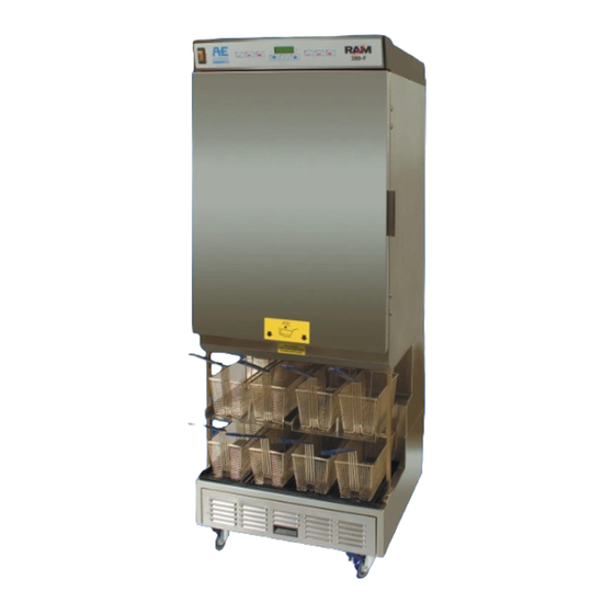
2 8 0 - F
Frozen Fry Dispenser
Equipment Manual
English (Rev H)
P/N 293511
Manufactured By
Automated Equipment LLC
5140 Moundview Drive
Red Wing, MN 55066 U.S.A.
For Warranty Service & Technical Support
:
US & Canada call: 1 (800) 248-2724
International call: 1 (651) 385-2273
Sales Fax: 1 (651) 385-2166
Service Fax: 1 (651) 385-2172
http://www.autoequipllc.com
Business Hours:
Monday - Friday: 8:00 AM to 5:00 PM CST
(excluding. holidays)
After hours, your call will be handled by a voice mail
paging service. The on-call technician will be paged and
will return your call.
Table of Contents
Introduction .............................................................................................................................................1
Unpacking & Installation ........................................................................................................................1
Intended Use ...........................................................................................................................................1
Specifications..........................................................................................................................................1
Warranty ..................................................................................................................................................2
Service Information ................................................................................................................................3
Equipment Safety....................................................................................................................................4
Dispenser Assembly (Models prior to s/n 28FR0802B0249)...............................................................6
Dispenser Assembly (Models after and including s/n 28FR0802B0249) ...........................................9
Disassembly, Defrost & Cleaning........................................................................................................12
Dispenser Startup .................................................................................................................................13
Operation ...............................................................................................................................................14
Daily Opening and Closing ..................................................................................................................15
User Function Menu Structure ............................................................................................................18
Manager Function Menu Structure......................................................................................................19
Diagnostic Function Menu Structure ..................................................................................................20
Error Detection......................................................................................................................................23
Troubleshooting....................................................................................................................................24
Calibrations and Adjustments .............................................................................................................27
Part Identification..................................................................................................................................30
Refrigeration System............................................................................................................................40
Electrical Diagram - Two Temperature Probe Configuration ...........................................................44
Electrical Diagram - Single Temperature Probe Configuration .......................................................45
Copyright © 2011
Automated Equipment LLC
All rights reserved.
Advertisement
Table of Contents

Related Manuals for AUTOMATED EQUIPMENT RAM 280-F

Summary of Contents for AUTOMATED EQUIPMENT RAM 280-F
-
Page 1: Table Of Contents
Frozen Fry Dispenser Equipment Manual English (Rev H) P/N 293511 Manufactured By Automated Equipment LLC 5140 Moundview Drive Red Wing, MN 55066 U.S.A. For Warranty Service & Technical Support US & Canada call: 1 (800) 248-2724 International call: 1 (651) 385-2273... - Page 2 This manual is copyrighted with all rights reserved. Under the copyright laws, this manual may not be copied, in whole or part, without the written consent of Automated Equipment LLC. Product names mentioned herein are for identification purposes only, and may be trademarks and/or registered trademarks of their respective companies.
-
Page 3: Introduction
Model if not installed and used in accordance with Manufacturing instruction manual, cause Facility interference to radio communications. Year Month Revision Level Sequence 00183 00294 Number Copyright © 2011 Automated Equipment LLC All rights reserved. -
Page 4: Warranty
RAM™ 280-F Frozen Fry Dispenser Warranty The terms "we", “us”, “our” or “factory” hereinafter refer to Automated Equipment LLC. We warrant the purchased product to be free from manufacturing defects in material and workmanship under normal use and conditions for the period and component specified below. -
Page 5: Service Information
All shipping charges are F.O.B. factory, and are subject to change without notice. Prices will be those in effect at the time of shipment. Automated Equipment LLC. reserves the right to make suitable substitutions in materials, depending upon their availability. -
Page 6: Equipment Safety
If the power cord is damaged, it must be replaced by the manufacturer, or its service agent, or a similarly qualified person in order to avoid a hazard. Copyright © 2011 Automated Equipment LLC All rights reserved. - Page 7 Label is located on Top Cover and Rear Access Panels. INDICATES HAZARDOUS VOLTAGE WITHIN Label is located near Power Cord inlet. CAUTION, RISK OF ELECTRIC SHOCK. DISCONNECT POWER BEFORE SERVICING UNIT. Copyright © 2011 Automated Equipment LLC All rights reserved.
-
Page 8: Dispenser Assembly (Models Prior To S/N 28Fr0802B0249)
Install the left and right Accumulator Doors by first inserting the rear of the doors onto the Accumulator Motor Shafts, then slide the Chucks forward and rotate the chucks clockwise until finger-tight. Install the left and right Accumulator Housings over the Accumulator Doors. Copyright © 2011 Automated Equipment LLC All rights reserved. - Page 9 Once the Accumulator Housings and Hopper Assemblies are in place, close the Cabinet Door. Assemble Basket Tray and Drip Tray to lower dispensing area. Basket Trays are not universal to the left and right positions. Copyright © 2011 Automated Equipment LLC All rights reserved.
- Page 10 RAM™ 280-F Frozen Fry Dispenser Using the Hash-brown Rack The RAM 280-F cabinet can be used to store frozen hash-browns while serving breakfast. To use the cabinet for hash-brown storage, properly assemble the dispenser (pages 6-11), then install the hash- brown rack accessory as shown in the diagram below.
-
Page 11: Dispenser Assembly (Models After And Including S/N 28Fr0802B0249)
(Accumulator Doors are hidden for clarity in Right Hand view). Accumulator Housing Assembly Install the left and right Accumulator Housings over the Accumulator Doors. Copyright © 2011 Automated Equipment LLC All rights reserved. - Page 12 Once the Accumulator Housings and Hopper Assemblies are in place, close the Cabinet Door. Assemble Basket Tray and Drip Tray to lower dispensing area. Basket Trays are not universal to the left and right positions. Copyright © 2011 Automated Equipment LLC All rights reserved.
- Page 13 RAM™ 280-F Frozen Fry Dispenser Using the Hash-brown Rack The RAM 280-F cabinet can be used to store frozen hash-browns while serving breakfast. To use the cabinet for hash-brown storage, properly assemble the dispenser (pages 9-11), then install the hash- brown rack accessory as shown in the diagram below.
-
Page 14: Disassembly, Defrost & Cleaning
Remove left and right Basket Guide assemblies from the Dispenser by lifting up on the front of the guide until it unlatches, then pull outward and upward. Remove Drip Tray by lifting, tilting and sliding forward. Copyright © 2011 Automated Equipment LLC All rights reserved. -
Page 15: Dispenser Startup
• Press the Enter Button to select the desired function. • Basket Size Buttons also function as numbers: (e.g. Left Small=1, Left Medium=2, Left Large=3, Right Small=4, Right Medium=5, Right Large=6) Copyright © 2011 Automated Equipment LLC All rights reserved. -
Page 16: Operation
Hopper wall opposite the Diverter. 6. This crisscross loading method assures an even distribution of fry lengths in the Hopper and the Baskets. 7. Repeat until each hopper is full. Copyright © 2011 Automated Equipment LLC All rights reserved. -
Page 17: Daily Opening And Closing
4 minutes. The weight selection will remain in the medium setting until the operator elects to change it. Copyright © 2011 Automated Equipment LLC All rights reserved. - Page 18 RAM 280-F Frozen Fry Dispenser. Copyright © 2011 Automated Equipment LLC All rights reserved.
- Page 19 Then press the Enter button. Note: The Basket Size Buttons also function as number buttons: (e.g. the left medium basket button is number 2, and the right large basket button is number 6.) Copyright © 2011 Automated Equipment LLC All rights reserved.
-
Page 20: User Function Menu Structure
*Service Password to access both the Manager Menu and Diagnostic Menu: 22463† †Note: Using the Service Password to access the Manager Function menu will erase the manager’s password (if set) and restore it to default (no password). Copyright © 2011 Automated Equipment LLC All rights reserved. -
Page 21: Manager Function Menu Structure
Service Password to access both the Manager Menu and Diagnostic Menu: 22463 Note: Using the Service Password to access the Manager Function menu will erase the manager’s password (if set) and restore it to default (no password). Copyright © 2011 Automated Equipment LLC All rights reserved. -
Page 22: Diagnostic Function Menu Structure
Control Probe Offset to 15°F(-3°C to 8°C). Up arrow will increase in 1° increments. Down arrow will decrease in 1° increments. Enter button will save the new setting and exit to D01 Copyright © 2011 Automated Equipment LLC All rights reserved. - Page 23 Note: Volatile Setting “[ on” (“ on ]”) Down arrow turns off the scale for selected side. “[ OFF” (“ OFF ]”) Enter button executes selection, exits function and returns to D01 Copyright © 2011 Automated Equipment LLC All rights reserved.
- Page 24 Service Password to access both the Manager Menu and Diagnostic Menu: 22463 Note: Using the Service Password to access the Manager Function menu will erase the manager’s password (if set) and restore it to default (no password). Copyright © 2011 Automated Equipment LLC All rights reserved.
-
Page 25: Error Detection
Enter Button. These errors are reset from the Diagnostic Menu using Diagnostic Function D08. Call our Technical Support Hot Line for assistance with these errors. Copyright © 2011 Automated Equipment LLC All rights reserved. -
Page 26: Troubleshooting
(i.e. fries jammed underneath). Verify the shaft collars are not rubbing the back wall of the cabinet. If no obstruction is found calibrate the scale. (Page Copyright © 2011 Automated Equipment LLC All rights reserved. - Page 27 US & Canada: 1 (800) 248-2724 International: 1 (651) 385-2273 After hours, your call will be handled by a voice mail paging service. The on call technician will be paged and will return your call. Copyright © 2011 Automated Equipment LLC All rights reserved.
- Page 28 R Basket Sensor lit: The right basket sensor has detected a basket. The example displayed left indicates the following inputs/outputs are on: Left Drum Motor Left Home Sensor Refrigeration Power Compressor Right Acc Motor Example Right Basket Sensor Copyright © 2011 Automated Equipment LLC All rights reserved.
-
Page 29: Calibrations And Adjustments
RAM™ 280-F Frozen Fry Dispenser Calibrations and Adjustments Scale Calibration The RAM 280-F Frozen Fry Dispenser will 9) Close the cabinet door. maintain and dispense fries from two hoppers. The dispenser will return to normal operation Each side has a scale which weighs and... - Page 30 Note: The Basket Size Buttons also function as the Enter Button. number buttons: (e.g. the left medium basket button is number 2, and the right large basket button is number 6.) Copyright © 2011 Automated Equipment LLC All rights reserved.
- Page 31 RAM™ 280-F Frozen Fry Dispenser Temperature Probe Calibration The RAM 280-F Frozen Fry Dispenser has If the difference between the display and the used different temperature control thermometer is greater than 2º, an adjustment configurations, one using a single probe and should be made.
-
Page 32: Part Identification
Screw, Hex-Head 5/16-18x3/4” 216595 Caster, Rear 200774 Screw, Hex-Head 5/16-18x3/4” 291050 Basket, Fry, Black Handle 294008 Case of 8 Fry Baskets 202523 Handle, Filter Drawer 294410 Label Kit Dispenser Cabinet Assembly (Front View) Copyright © 2011 Automated Equipment LLC All rights reserved. - Page 33 Screw, Hex-Hd Cap 5/16-18x3/4” 202523 Handle, Snap In 294410 Label Kit Dispenser Cabinet (rear view) For models prior to s/n 28FR0710A00153 Lower Back Panel For models after and including s/n 28FR0710A00153 Copyright © 2011 Automated Equipment LLC All rights reserved.
- Page 34 Door Accumulator LH (Units after and including sn 28FR0802B00249) 293737 Door, Accumulator, RH ( Units prior to sn 28FR0802B0249) 294391 Door Accumulator RH (Units after and including sn 28FR0802B00249) 293376 Door, Flap Copyright © 2011 Automated Equipment LLC All rights reserved.
- Page 35 293650 Gasket, Hopper Support Bar 293720 Screw, Flat-head, slotted, SS #10-32x 1” 293260 Hopper Support Pad, Center 294407 Door Switch 293720 Screw, Flat-head, slotted, SS #10-32x 1” 294408 Door Switch Harness Copyright © 2011 Automated Equipment LLC All rights reserved.
- Page 36 Drip Pan Assembly w/ tape 293731 Spacer, Nylon, ¼”x#8x3/8” 293934 Basket Sensor 293415 Accumulator Heater Wire Domestic 293707 Gasket, Sensor Window 294261 Accumulator Heater Wire Int. 220V (not pictured) 294593 Sensor Window Kit Copyright © 2011 Automated Equipment LLC All rights reserved.
- Page 37 Bracket, Spring Base 293154 Accumulator Toggle 213262 Screw, Socket-head cap, M6x1x16mm 213549 Screw, socket, flat-head, ¼”-20x⅝” 204761 Nut, Nylon lock, Hex, 18-8 SS, 5/16-18 203259 Bearing, Sleeve, ¼”ID x 5/16”OD x ¼” Copyright © 2011 Automated Equipment LLC All rights reserved.
- Page 38 291308 Screw, Trusshead, Phillips, #8-32x1¼” 293879 Coupler Nut, Accumulator Door 290519 Circuit Board, NCWS 293596 Collar, Accumulator shaft, UHMW 292252 Standoff, Nylon, Unthreaded, 0.75”L 213549 FH Cap Screw, Socket, ZP, ¼-20x5/8”L Copyright © 2011 Automated Equipment LLC All rights reserved.
- Page 39 (293908, previous page) and replace with items 17 & 18 shown here, the old style NCWS base (item 12) and Accumulator housings (Item 5 on page 32) also need to be upgraded. Copyright © 2011 Automated Equipment LLC All rights reserved.
- Page 40 AC Power Harness (Power Supply to Control Board) Terminal Block) 293411 Motor Control Harness Domestic 120V 293333 Cabinet Door Heater Wire-Domestic 120V 294011 Motor Control Harness International 220V 294262 Cabinet Door Heater Wire International 220V Copyright © 2011 Automated Equipment LLC All rights reserved.
- Page 41 Right Accum Motor +24VDC (A7) Not used Not used Right Accum Motor (A8) Right Basket Sensor (S1) Refrigeration Control Probe PART # DESCRIPTION 293807 Display Board 293902 Ribbon Cable, Display Board (not pictured) Copyright © 2011 Automated Equipment LLC All rights reserved.
-
Page 42: Refrigeration System
RAM™ 280-F Frozen Fry Dispenser Refrigeration System General Operation Required Maintenance The RAM 280-F employs a cold wall system. Daily: Through the refrigeration process, heat is • Shut off, clean, defrost and inspect cabinet. transferred to the condensing unit at the bottom... - Page 43 290529 Nut ZP 4-40 (not pictured) 293415 Heater Wire, Accum. (Dom. 120V) 294261 Heater Wire, Accum. (Int. 220V) (not pictured) 293734 Feedback Relay (Dom.120V) 293974 Feedback Relay (Int. 240V) (not pictured) Copyright © 2011 Automated Equipment LLC All rights reserved.
- Page 44 294723 -240V 50HZ 1/2HR / Rev. D Differential setpoint: 5°F (3°C) Control probe offset: 0°F (0°C) High Pressure switch trips at 425 psi (2890 kPa) resets at 325 psi (2210 kPa) Compressor Start Component Wiring Copyright © 2011 Automated Equipment LLC All rights reserved.
- Page 45 RAM™ 280-F Frozen Fry Dispenser Refrigeration Circuit Copyright © 2011 Automated Equipment LLC All rights reserved.
-
Page 46: Electrical Diagram - Two Temperature Probe Configuration
RAM™ 280-F Frozen Fry Dispenser Electrical Diagram – Two Temperature Probe Configuration Note: Door switch only applies to revision C dispensers and later. Copyright © 2011 Automated Equipment LLC All rights reserved. -
Page 47: Electrical Diagram - Single Temperature Probe Configuration
RAM™ 280-F Frozen Fry Dispenser Electrical Diagram – Single Temperature Probe Configuration Copyright © 2011 Automated Equipment LLC All rights reserved. - Page 48 RAM™ 280-F Frozen Fry Dispenser Notes: Copyright © 2011 Automated Equipment LLC All rights reserved.
Need help?
Do you have a question about the RAM 280-F and is the answer not in the manual?
Questions and answers