Advertisement
"EZ UP" ALIGNMENT HINGE
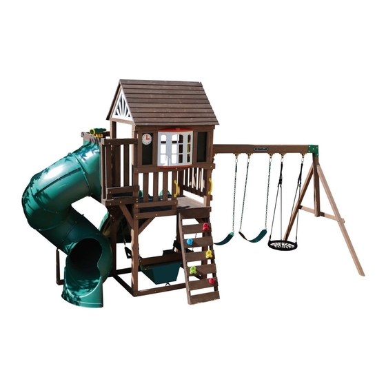
This swing set features the KidKraft "EZ UP" alignment hinge for
quick and easy fort frame assembly in Step 2 - 7.
The living hinge is not required for swing set structural integrity.
Complete the swing set build by following the instruction manual
steps, guidelines, and all other proper maintenance and care to
achieve a safe and quality product.
Advertisement

Related Manuals for KidKraft PORTLAND SWING SET


Summary of Contents for KidKraft PORTLAND SWING SET
- Page 1 “EZ UP” ALIGNMENT HINGE This swing set features the KidKraft “EZ UP” alignment hinge for quick and easy fort frame assembly in Step 2 - 7. The living hinge is not required for swing set structural integrity. Complete the swing set build by following the instruction manual steps, guidelines, and all other proper maintenance and care to achieve a safe and quality product.
-
Page 2: Table Of Contents
KidKraft, Inc. KidKraft Netherlands BV Keys to Assembly Success . . . . . . . . . . . . . . . . . . . . pg . 7... -
Page 3: Warnings And Safe Play Instructions
Warnings and Safe Play Instructions CONTINUOUS ADULT SUPERVISION REQUIRED. Most serious injuries and deaths on playground equipment have occurred while children were unsupervised! Our products are designed to meet mandatory and voluntary safety standards. Complying with all warnings and recommendations in these instructions will reduce the risk of serious or fatal injury to children using this play system. -
Page 4: Protective Surfacing Guidelines
Protective Surfacing - Reducing Risk of Serious Head Injury From Falls One of the most important things you can do to reduce the likelihood of serious head injuries is to install shock-absorbing protective surfacing under and around your play equipment. The protective surfacing should be applied to a depth that is suitable for the equipment height in accordance with ASTM F1292. -
Page 5: Instructions For Proper Maintenance
Instructions for Proper Maintenance Your KidKraft Play System is designed and constructed of quality materials with your child’s safety in mind. As with all outdoor products used by children, it will weather and wear. To maximize the enjoyment, safety and life of your Play Set, it is important that you, the owner, properly maintain it. -
Page 6: About Our Wood - Limited Warranty
About Our Wood KidKraft Premium Play Systems uses only premium playset lumber, ensuring the safest product for your children’s use. Although we take great care in selecting the best quality lumber available, wood is still a product of nature and susceptible to weathering which can change the appearance of your set. - Page 7 KidKraft Limited Warranty MISSING OR DAMAGED PARTS: KidKraft will replace any parts within 90 days from date of purchase found to be missing from or damaged in the original packaging. See Fig.1 Fig. 1 Product Age (All Parts) Consumer Pays...
-
Page 8: Keys To Assembly Success
Keys to Assembly Success Tools Required • Tape Measure • #1 Phillips, #2 Robertson • Open End Wrench • 3/16”(5mm) Hex Key • Carpenters Level and Screwdriver 1/2” (13mm) & 9/16”(14 mm) • 8’ (2.4m) Step Ladder • Carpenters Square •... -
Page 9: Part Id
Part Identification (Reduced Part Size) - BOX 1 1x - 9686 - 31.8 x 76.2 x 1251.0mm - 3839686 1 1/4" X 3" X 49 1/4" 1x - 9687 - 31.8 x 63.5 x 660.4mm - 3839687 1 1/4" X 2 1/2" X 26" 1x - 9688 - 25.4 x 76.2 x 635 mm - 3839688 1"... - Page 10 Part Identification (Reduced Part Size) - BOX 1 2x - 9718 - 15.9 x 133.4 x 482.6mm - 3589718 5/8" X 5 1/4" X 19" 2x - 9720 - 50.8 x 76.2 x 2063.9mm - 3839720 2" X 3" X 81 1/4" 1x - 8965 - 31.8 x 76.2 x 514.4 mm - 3838965 1 1/4"...
- Page 11 Part Identification (Reduced Part Size) - BOX 1 1x - 9297 - 108 x 914 x 2336.6mm - 37839297 4-1/4" X 36" X 92" 39839403 37839296 39839402 39839402 If you need to order parts, please order below part # 37839296 - Open Panel - 1pc - 52213230 9327884 39839402 - Swing Arm -1pc...
- Page 12 Part Identification (Reduced Part Size) - BOX 2 2x - 9700 - 31.8 x 76.2 x 876.3 mm - 3589700 1 1/4" X 3" X 34 1/2" 1x - 9706 - 15.9 x 114.3 x 977.9 mm - 3589706 5/8" X 4 1/2" X 38 1/2" 2x - 9707 - 15.9 x 114.3 x 977.9 mm - 3589707 5/8"...
- Page 13 Part Identification (Reduced Part Size) - BOX 2 8x - 9731 - 31.8 x 63.5 x 381 mm - 3839731 1 1/4" X 2 1/2" X 15" 2x - 9732 - 31.8 x 76.2 x 530 mm - 3839732 1 1/4" X 3" X 20 7/8" 1x - 9735 - 31.8 x 31.8 x 914.4 mm - 3839735 1 1/4"...
- Page 14 Part Identification (Reduced Part Size) Part Identification (Reduced Part Size) Part Identification (Reduced Part Size) - BOX 2 1x - 9295 - 108 x 914 x 2336.6 - 37839295 4 1/4" X 36" X 92" 37839294 39839403 39839402 39839402 If you need to order parts, please order below part # 37839294 - SW Panel - 1pc 39839402 - Swing Arm -1pc 9327884...
- Page 15 Hardware Identification (Actual Size) 5x - FW0 - 3/16" - (51103100) 36x - LW2 - 5/16" - (51303300) 34x - TN1 - 1/4" (54503200) 4.8mm 6.4mm 7.9mm 39x - FW1 - 1/4" - (51103200) 6.4mm 24x - LW1 - 1/4" - (51303200) 6.4mm 42x - TN2 - 5/16"...
- Page 16 Hardware Identification (Actual Size) " 49x - PB1 - 1/4 x 3/4 - (53413203) 5/16 x 1-3/8" 10x - WB2 - - (53613316) 6.4 x 19.1mm 7.9 x 25.4mm " 11x - PB6 - 1/4 x 1 - (53413210) 6.4 x 25.4mm 5/16 x 2-3/8"...
- Page 17 Part Identification (Reduced Part Size) 1x - (3200718)(7pk) 1x - (3310123) 7x - (9290318)(1pk) 1x - (3320353) 1x - (3310122) 1x - (9320374) 1x - (3329190)(5pk) 1x - (3200106)(4pk) 1x - (3320161) 2x - (9320130) 1x - (3320255) 2x - (3320704) 1x - (9200168) 9x - (3310121) 1x - (3200145)(2pk)
- Page 18 Part Identification (Reduced Part Size) 1x - (3720002) - (3720001) 1x - (5799192) 8x - (3799194) 24x - (3799193) 1x - (3759190)
-
Page 19: Step-By-Step Instructions
Before you discard your cartons fill out the form below. • The carton I.D. stamp is located on the end of each carton. The tracking number is located on the KidKraft ID Plaque (9320374). • Please retain this information for future reference. You will need this information if you contact the Consumer Relations Department. - Page 20 Step 2 9295 Wood Parts Hardware 108 x 914 x 2336.8mm (4-1/4” x 36” x 92”) 9295...
- Page 21 Step 3 9295 Preassembled on the post 9295 Preassembled on the post Preassembled on the post...
- Page 22 Step 4 9295 3200132 3200132 3200132 Hardware Other Parts #8 x 22.2mm (#8 x 7/8”) 3200132...
- Page 23 Step 5 9297 Preassembled on the post 9297 Preassembled on the post Preassembled on the post Wood Parts 108 x 914 x 2336.8mm (4-1/4” x 36” x 92”) 9297...
- Page 24 Step 6 3200132 3200132 9297 3200132 Hardware Other Parts #8 x 22.2mm (#8 x 7/8”) 3200132...
- Page 25 Step 7 9297 9295 Hardware 7.9mm x 35 mm (5/16 x 1-3/8”)(FW2, LW2, TN2)
- Page 26 22" 558.8 AI-4 Step 8 WL5 X 6(FW2) Pre-drill each hole using a 3/16” drill bit. 22" AI-4 558.8 22" WL5 X 6(FW2) 558.8 9686 22" 558.8 9685 9686 Flush 9685 9685 Flush 9685 Wood Parts Hardware 31.8 x 76.2 x 1219.2 mm (1-1/4” x 3” x 48”) 6.4mm x 63.5 mm (1/4 x 2-1/2”)(FW2) 9685 31.8 x 76.2 x 1251.0 mm (1-1/4”...
- Page 27 Step 9 9690 WB10 WB10 9690 WB10 9690 WB10 9690 1 1/2” WB10 Drill 1/8” WB10 Through hole Frame Only 6” 6” 15.8mm 5/8” 9690 Wood Parts Hardware 38.1 x 38.1 x 1062.8 mm (1-1/2” x 1-1/2” x 41-13/16”) 7.9mm x 66.6 mm (5/16 x 2-5/8”)(FW2, TN2) WB10 9690 #8 x 64mm (#8 x 2-1/2”)
- Page 28 AI-6a Step 10 S20 X 4 AI-6a S20 X 4 9693 9693 9693 Wood Parts Hardware 15.9 x 114.3 x 882.6 mm (5/8” x 4 1/2” x 34 3/4”) #8 x 35mm (#8 x 1-3/8”) 9693...
- Page 29 Step 11 9693 9715 9693 9715 9693 9693 Wood Parts Hardware 31.8 x 76.2 x 1154.6 mm (1-1/4” X 3” X 45 7/16”) #8 x 35mm (#8 x 1-3/8”) 9715 #8 x 76.2mm (#8 x 3”)
- Page 30 Step 12 9692 9692 9692 Wood Parts Hardware 15.9 x 114.3 x 882.6 mm (5/8” X 4 1/2” X 34 3/4”) 48 x #8 x 35mm (#8 x 1-3/8”) 9692...
- Page 31 Step 13 AI-8 S11 X 4 Center Top (9721) 9721 Wood Parts Hardware 31.8 x 31.8 x 1064.8 mm (1-1/4” x 1-1/4” x 41-15/16”) #8 x 50.8mm (#8 x 2”) 9721...
- Page 32 Step 14 9689 AI-9 WB7 X 8(FW2,TN2) 9689 9689 9689 9689 Wood Parts Hardware 76.2 x 76.2 x 186.6 mm (3” x 3” x 7-3/8”) 7.9mm x 76.2mm (5/16 x3”)(FW2, TN2 ) 9689...
- Page 33 AI-10 Step 15 x 2 S4 X 16(2PCS) 9695 9694 9694 9695 Wood Parts Hardware 31.8 x 63.5 x 421.0 mm (1-1/4” x 2-1/2” x 16-9/16”) 16 x #8 x 76.2mm (#8 x 3”) 9694 31.8 x 31.8 x 285.9 mm (1-1/4” x 1-1/4” x 11-1/4”) 9695...
- Page 34 Step 16 AI-11 Notice hole S3 X 12 orientation 9691 AI-11 9691 S3 X 12 50.8mm 2” 50.8mm 2” 9691 Wood Parts Hardware 31.8 x 63.5 x 1219.2 mm (1-1/4” x 2-1/2” x 48”) 12 x #8 x 64mm (#8 x 2-1/2”) 9691...
- Page 35 AI-12 H3 X 2(FW1 , LW1 , TN1) Step 17 WL5 X 1(FW2) AI-12 H3 X 2(FW1 , LW1 , TN1) WL5 X 1(FW2) 9688 AI-12 H3 X 2(FW1 , LW1 , TN1) 9687 WL5 X 1(FW2) 9688 9687 9687 Pre-drill each hole using a 3/16”...
- Page 36 Step 18 AI-13 S37 X 3 9201570 Hardware Other Parts 9201570 #7 x 15.87mm (#7 x 5/8”)
- Page 37 Step 19 Making sure that they are square Flush Flush 9714 9714 T-nuts previously installed in Step 2 Hardware Wood Parts 31.8 x 133.4 x 914.4 mm (1-1/4” x 5-1/4” x 36”) 6.4mm x 108mm (1/4 x 4-1/4”)(FW1, LW1, TN1) 9714 6.4mm x 108mm (1/4 x 4-1/4”)(FW1, LW1)
- Page 38 Step 20 Pre-drill each hole using a 3/16” drill bit for WL5. Pre-drill hole using the 1/8” drill bit (2) Flush 9735 9696 9735 9696 25.4mm 1” 9696 85.7mm 3-3/8” Hardware Wood Parts 6.4mm x 63.5 mm (1/4 x 2-1/2”)(FW2) 31.8 x 31.8 x 914.4 mm (1-1/ 4”...
- Page 39 Step 21 AI-16 S20 X 20 Center the first board 63.5 mm 2-1/2” 9697 9697 9697 9697 9697 9697 9697 9697 9697 9697 beveled edge faces out 9697 beveled edge faces out Wood Parts Hardware 15.9 x 76.2 x 549.0 mm (5/8” x 3” x 21-5/8”) 9697 20 x #8 x 35mm (#8 x 1-3/8”)
- Page 40 Step 22 Center the first board 70 mm 2-3/4” 9697 beveled edge faces out 9697 9697 9697 Wood Parts Hardware 15.9 x 76.2 x 549.0 mm (5/8” x 3” x 21-5/8”) 12 x #8 x 35mm (#8 x 1-3/8”) 9697...
- Page 41 AI-18 Step 23 WL5 X 16(FW2) Pre-drill each hole using a 3/16” drill bit. 9731 9731 9731 9731 Wood Parts Hardware 31.8 x 63.5 x 381.0 mm (1-1/4” x 2-1/2” x 15”) 16 x 6.4mm x 63.5 mm (1/4 x 2-1/2”)(FW2) 9731...
- Page 42 S0 X 12 Step 24 AI-19 S0 X 12 3320704 3320704 Hardware Other Parts 2 x 3320704 12 x #8 x 22.2mm (#8 x 7/8”)
- Page 43 Step 25 AI-20 AI-20 S0 X 14 S0 X 14 S37 X 8 S37 X 8 3320341 3320341 3320341 Hardware Other Parts 1 x 3320341 #7 x 15.87mm (#7 x 5/8”) #8 x 22.2mm (#8 x 7/8”)
- Page 44 Step 26 3320341 Hardware #8 x 22.2mm (#8 x 7/8”)
- Page 45 Step 27 Hardware #7 x 15.87mm (#7 x 5/8”) #8 x 22.2mm (#8 x 7/8”)
- Page 46 Step 28 2 X 2 eded for t step* 9297 9297 Hardware...
- Page 47 Step 29 9704 Flush 9704 143 mm 5-5/8” 9704 Wood Parts Hardware 31.8 x 76.2 x 759.9 mm (1-1/4” x 3” x 29-15/16”) #10 x 101.6mm (#10 x 4”) 9704...
- Page 48 Step 30 *Note: TN2's installed on step 21 **Note: I used G21 in the model because G4 was too long. FW2 LW2 9698 9745 Wood Parts Hardware 31.8 x 76.2 x 457.2 mm (1-1/4” x 3” x 18”) 7.9mm x 95 mm (5/16 x 3-3/4”) ( LW2,FW2) 9698 31.8 x 76.2 x 457.2 mm (1-1/4”...
- Page 49 Step 31 2(FW1, TN1) X 2(FW2) Pre-drill each hole using a 3/16” drill bit. AI-23 H2 X 2(FW1, TN1) 9732 WL5 X 2(FW2) 9732 9732 Wood Parts Hardware 6.4mm x 63.5 mm (1/4 x 2-1/2”)(FW2) 31.8 x 76.2 x 530.0 mm (1-1/4” x 3” x 20 7/8”) 9732 6.4mm x 50.8mm (1/4 x 2”)(FW1, LW1, TN1)
- Page 50 Step 32 AI-25 G21 X2 the rail that is 1" shorter goes against the chalk clock AI-25 G21 X2 the rail that is 1" shorter goes against the chalk clock frame Shorter Rail goes against Chalk Clock frame. 9746 9709 Wood Parts Hardware 7.9mm x 95 mm (5/16 x 3-3/4”) ( LW2, FW2 , TN2)
- Page 51 Step 33 Install TN2 (will be used in Step 35) 2-1/2" Hex) in the cad model** 9700 9700 9700 Wood Parts Hardware 31.8 x 76.2 x 876.3 mm (1-1/4” x 3” x 34-1/2”) 6.4mm x 50.8 mm (1/4 x 2”) (LW1,FW1,TN1) 9700 7.9 mm (5/16”)
- Page 52 AI-27 WB2 X 4(FW2, LW2, TN2) Step 34 9701 9702 9702 9701 Wood Parts Hardware 31.8 x 76.2 x 977.9 mm (1-1/4” x 3” x 38-1/2”) 7.9mm x 35 mm (5/16 x 1-3/8”)(FW2, LW2, TN2) 9701 31.8 x 76.2 x 876.3 mm (1-1/4” x 3” x 34-1/2”) 9702...
- Page 53 Step 35 AI-28 G4 X 4(FW2, LW2, TN2) Hardware 7.9mm x 101.6mm (5/16 x 4”)(LW2,FW2)
- Page 54 AI-29 Step 36 S4 X 4 9705 Wood Parts Hardware #8 x 76.2mm (#8 x 3”) 31.8 x 63.5 x 424.4 mm (1-1/4” x 2 1/2” x 16-11/16”) 9705...
- Page 55 S20 X 24 Step 37 9708 9707 9707 9706 Wood Parts Hardware 15.9 x 114.3 x 977.9 mm (5/8” x 4-1/2” x 38-1/2”) 9706 24 x #8 x 35mm (#8 x 1-3/8”) 15.9 x 114.3 x 977.9 mm (5/8” x 4-1/2” x 38-1/2”) 9707 15.9 x 109.0 x 977.9 mm (5/8”...
- Page 56 Step 38 9699 9746 Wood Parts Hardware 6.4mm x 50.8 mm (1/4 x 2”) (LW1,FW1,TN1) 31.8 x 76.2 x 457.2 mm (1-1/4” x 3” x 18”) 9746 31.8 x 76.2 x 457.2 mm (1-1/4” x 3” x 18”) 9699 7.9mm x 95 mm (5/16 x 3-3/4”) ( LW2, FW2 , TN2) #8 x 76.2mm (#8 x 3”)
- Page 57 Step 39 50.8 mm 2” 9703 9703 9703 9703 9703 9703 Wood Parts Hardware 15.9 x 76.2 x 715.1 mm (5/8” x 3” x 28-1/8”) 16 x #8 x 35mm (#8 x 1-3/8”) 9703...
- Page 58 AI-31 Step 40 S20 X 12 9711 9711 9711 Wood Parts Hardware 15.9 x 76.2 x 914.4 mm (5/8” x 3” x 36”) 13 x #8 x 35mm (#8 x 1-3/8”) 9711...
- Page 59 AI-31.5 Step 41 9710 Wood Parts Hardware 31.8 x 31.8 x 650.0 mm (1-1/4” X 1 1/4” X 25-9/16”) #8 x 76.2mm (#8 x 3”) 9710...
- Page 60 Step 42 x 2 choose the image you like best, they are the same 9713 9713 9712 Wood Parts Hardware 31.8 x 50.8 x 1079.5 mm (1-1/4” x 2” x 42-1/2”) #8 x 64mm (#8 x 2-1/2”) 9712 31.8 x 50.8 x 691.1 mm (1-1/4” x 2” x 27-3/16”) 9713 #8 x 76.2mm (#8 x 3”)
- Page 61 Step 43 x 2 choose the image you like best, they are the same 9330518 Hardware Other Parts 2 x 9330518 18 x #8 x 22.2mm (#8 x 7/8”)
- Page 62 Step 44 AI-34 S0 X 6 9292 9293 9292 3200132 9293 9292 3200132 3200132 3200132 9293 Note! Install 3200132 bracket flush to outside edge. Wood Parts Hardware Other Parts 28.6 x 1270 x 801.7 mm (1-1/8” x 50” x 31-13/16”) #8 x 22.2mm (#8 x 7/8”) 9292 3200132...
- Page 63 S11 X 8 gable flush to inside edge on both sides Step 45 gable flush to inside edge on both sides gable flush to inside edge on both sides Gables should be flush to inside edges on both sides 9713 9713 Hardware #8 x 50.8mm (#8 x 2”)
- Page 64 AI-36 H12 X 4(FW1, LW1, TN1) Step 46 AI-36 H12 X 4(FW1, LW1, TN1) Align both holes before inserting bolt. Hardware 6.4mm x 76.2 mm (1/4 x 3”) (FW1, LW1, TN1)
- Page 65 Step 47 IMPORTANT! Follow hole pattern 9718 9717 9716 Do not attach Put aside until Step 50 Center first board and evenly space remaining 9718 9717 9717 9717 9717 9717 9718 9716 AI-38 9716 S20 X 4 AI-38 S20 X 4 9719 Hardware Wood Parts...
- Page 66 Step 48 Note: Make sure all hardware is used to properly secure each rock. 3329190 AI-39 PB2 X 5(FWO,LW1,BN1) S10 X 5 3329190 Hardware Other Parts 7.9mm x 32 mm (5/16 x 1-1/4”) (FW0,LW1,BN1) 3329190 #8 x 25.4 mm (#8 x 1”)
- Page 67 AI-40 S20 X 2 Step 49 AI-40 S20 X 2 AI-40 S20 X 2 9719 9719 9719 Hardware #8 x 35mm (#8 x 1-3/8”)
- Page 68 AI-40b S7 X 4 AI-40b S7 X 4 Step 50 9718 9718 Hardware #12 x 50.8mm (#12 x 2”)
- Page 69 Step 51 3320240 3320240 (203mm) 8” Pre-drill each hole using a 1/8” drill bit. Hardware Other Parts 3320240 6.4mm x 35mm (1/4 x 1-3/8”)(FW1)
- Page 70 Step 52 x 4 3310121 3310121 Hardware Other Parts 32 x 6.3mm x 19 mm (1/4 x 3/4”) (LN1) 3310121...
- Page 71 Step 53 3310122 3310123 Hardware Other Parts 6.3mm x 19 mm (1/4 x 3/4”) (LN1) 3310122 3310123...
- Page 72 Step 54 3310124 3310121 Hardware Other Parts 3310124 6.3mm x 19 mm (1/4 x 3/4”) (LN1) 3310121...
- Page 73 Step 55 Pre-drill each hole using a 1/8” drill bit. Making sure the pre-drilled holes are a minimum of 1” deep. Hardware 10 x #12 x 25.4mm (#12 x 1”) #12 x 50.8mm (#12 x 2”)
- Page 74 Step 56 Quadrex Driver Note: Keep all bolts loose until further step. Use Quadrex Driver as a guide pin for each hole before inserting bolt. Align each elbow using the molded arrows. Use special driver provided in locations where the curve of the elbow are difficult to reach with a standard driver.
- Page 75 Step 57 x 3 Quadrex Driver Note: Keep all bolts loose until further step. Use Quadrex Driver as a guide pin for each hole before inserting bolt. Use special driver provided in locations where the curve of the elbow are difficult to reach with a standard driver.
- Page 76 Step 58 Use a 7/16” open end wrench to hold nut and then tighten bolt with Quadrex Driver. 3310124 3310121 3310132 3310121 3310132 Hardware Other Parts 6.4mm x 19 mm (1/4 x 3/4”) (LN1) 3310132...
- Page 77 Step 59 Tighten all slide bolts before the clamp rings go on in the next step. 54902200 54902200 53453202 53453202 54902200 53453202 53453202 54902200 53453202 54902200 Align each elbow using the molded arrows. 53453202 54902200 Other Parts 54902200 1/4” x 12.7mm 53453202...
- Page 78 Step 60 Warning. Do not over tighten the clamp rings. 9300130 9300130 After the clamp rings are attached to the elbows, fasten them end to end 9300130 with two pan bolts and lock nuts 9300130 9300130 9300130 9300130 Note: For ease of assembly bottom set of clamp rings can be rotated 90...
- Page 79 Step 61 Remove PB1 (1/4 x 3/4” Pan Bolt), The bolt (PB1) will no longer be needed, but keep the lock nut (LN1) 9200168 Note: Flat end down Install PB6 (1/4 x 1” Pan Bolt with flat washer (FW1) Hardware Other Parts 6.4mm x 25.4 mm (1/4 x 1”) (FW1) 9200168...
- Page 80 Step 62 Hardware #12 x 25.4mm (#12 x 1”)
- Page 81 Step 63 8965 9722 Hardware Wood Parts 6.4mm x 108mm (1/4 x 4-1/4”)(FW1, LW1, TN1) 31.8 x 76.2 x 514.4 mm (1-1/4” x 3” x 20-1/4”) 8965 31.8 x 76.2 x 857.3 mm (1-1/4” x 3” x 33-3/4”) 9722 #8 x 64mm (#8 x 2-1/2”)
- Page 82 Step 64 9200157 53452209 9200157 54902200 9200156 9200156 Hardware Other Parts #7 x 15.87mm (#7 x 5/8”) 54902200 9200157 #12 x 25.4mm (#12 x 1”) 1/4 x 14.5mm 9200156 53452209 #8 x 64mm (#8 x 2-1/2”)
- Page 83 Step 65 MOVE FORT TO FINAL LOCATION PRIOR TO STAKING FINAL LOCATION MUST BE LEVEL GROUND Warning! To prevent tipping and avoid potential injury, stakes must be driven 13”(330mm) into ground. Digging or driving stakes can be dangerous if you do not check first for under- 9290318 ground wiring, cables or gas lines.
- Page 84 AI-42 Step 66 WB8 X 1(FW2,TN2) 3320255 Hardware Other Parts 3320255 7.9mm x 60.3 mm (5/16 x 2-3/8”)(FW2, TN2)
- Page 85 Step 67 3320161 Hardware Other Parts 3320161 #8 x 35mm (#8 x 1-3/8”)
- Page 86 Step 68 Notice hole orientation 3720002 3799194 Other Parts 3799194 3720002...
- Page 87 Step 69 3720002...
- Page 88 Step 70 9729 9729 9730 Notice hole orientation 3799193 Other Parts Wood Parts 3799193 23.8 x 101.6 x 584.8 mm (15/16” x 4” x 23”) 9729 23.8 x 101.6 x 584.8 mm (15/16” x 4” x 23”) 9730...
- Page 89 Step 71 9727 9728 9728 9727 3799193 Wood Parts Other Parts 23.8 x 82.6 x 584.8 mm (15/16” x 3-1/4” x 23”) 3799193 9727 23.8 x 82.6 x 500.2 mm (15/16” x 3-1/4” x 19-11/16”) 9728...
- Page 90 Step 72 9726 9725 3799193 Wood Parts Other Parts 23.8 x 82.6 x 761.2 mm (15/16” x 3-1/4” x 30”) 3799193 9725 23.8 x 82.6 x 592.3 mm (15/16” x 3-1/4” x 23-5/16”) 9726...
- Page 91 Step 73 9723 3799193 9723 Wood Parts Other Parts 23.8 x 82.6 x 896.1 mm (15/16” x 3-1/4” x 35-1/4”) 3799193 9723...
- Page 92 Step 74 3799193 9724 9724 Wood Parts Other Parts 23.8 x 82.6 x 584.8 mm (15/16” x 3-1/4” x 23”) 3799193 9724...
- Page 93 Step 75 3759190 Other Parts 3759190...
- Page 94 Step 76...
- Page 95 Step 77 9725 25.4 mm 25.4 mm 1” 1” 9725 25.4 mm 25.4 mm 1” 1” 9729 9730 9729 Hardware #7 x 15.87mm (#7 x 5/8”)
- Page 96 Step 78 9729 63.5 mm 230 mm 230 mm 63.5 mm 2-1/2” 9” 9” 2-1/2” Hardware #7 x 15.87mm (#7 x 5/8”)
- Page 97 Step 79 9729 63.5 mm 230 mm 230 mm 63.5 mm 2-1/2” 9” 9” 2-1/2” Hardware #7 x 15.87mm (#7 x 5/8”)
- Page 98 Step 80 3200106 Hidden 3200106 3200106 Hidden 3200106 3200106 Hardware Other Parts 3200106 6.4mm x 38.1mm (1/4 x 1-1/2”)(FW1, TN1)
- Page 99 Step 81 Tighten Threaded Quick Link Quick Link using adjustable wrench 3720002 Caution: Threaded Quick Links must be installed with the gate completely down covering the threads and tighten as instructed. 3720002 Quick Link Tighten Threaded Link Threaded Quick Links attach using adjustable wrench to chat swing and the fort.
- Page 100 Step 82 3720002...
- Page 101 S7 X 6 Step 83 Note: Pre-drill all holes using a 1/8” drill bit before installing the S7 screws. 7310149 7310149 Hardware Other Parts #12 x 50.8mm (#12 x 2”) 7310149...
- Page 102 Step 84 Notice Angle Orientation 3201950 2614 Wood Parts Hardware Other Parts 76.2 x 133.4 x 2235.2 mm (3” x 5-1/4” x 88”) 3201950 12 x 7.9mm x 139.7 mm (5/16 x 5-1/2”) ( LN2, 2 x FW2) 2614...
- Page 103 Step 85 IT IS IMPORTANT THAT THIS BOLT IS ATTACHED. IT WILL MINIMIZE CHECKING OF WOOD. Caution: The Spring Loaded Quick Link must be attached to the Heavy Duty Swing Hanger in the closed position. Hardware 7.9mm x 76.2mm (5/16 x3”)( FW2 , TN2 )
- Page 104 Step 86 3320353 3200145 3200145 Hardware Other Parts 7.9mm x 95 mm (5/16 x 3-3/4”) ( LN2, 2 x FW2) 3200145 3320353 #6 x 25.4mm (#6 x 1”)
- Page 105 Step 87 Notice Angle Orientation 9720 2615 9720 Wood Parts Hardware 50.8 x 76.2 x 2063.9 mm (2” x 3” x 81-1/4”) 9720 7.9mm x 139.7 mm (5/16 x 5-1/2”) ( LW2,FW2,TN2) 76.2 x 76.2 x 1294.3 mm (3” x 3” x 50-15/16”) 2615...
- Page 106 Step 88 IT IS IMPORTANT THAT THESE BOLTS ARE ATTACHED. THEY WILL MINIMIZE CHECKING OF WOOD. 2616 2616 Wood Parts Hardware 23.8 x 82.6 x 1181.1mm (15/16” x 3-1/4” x 46-1/2”) 7.9mm x 101.6mm (5/16 x 4”)(LW2,FW2,TN2) 2616 7.9mm x 76.2mm (5/16 x3”)( LW2,FW2,TN2)
- Page 107 Step 89 9200243 G21 G21 9200244 Hardware Other Parts 9200243 7.9mm x 95 mm (5/16 x 3-3/4”) ( LN2, 2 x FW2) 9200244...
- Page 108 Step 90 Hardware 7.9mm x 50.8 mm (5/16 x2”) ( LN2, 2 x FW2)
- Page 109 Step 91 x 2 3200172 3200172 3201950 3201950 Caution: Threaded Quick Links must be installed with the gate completely down covering the 9320130 threads and tighten as instructed. 3200172 3201950 Quick Link Threaded Quick Links Tighten Threaded Quick attach to seat. Link using adjustable wrench Other Parts...
- Page 110 Step 92 3201950 3201950 3200172...
- Page 111 Step 93 3201950 3201950 3720001 3720001 Other Parts 3720001...
- Page 112 Step 94 Adjust swing ropes as needed to ensure that swing is level.
- Page 113 Step 95 Warning! To prevent tipping and avoid potential injury, stakes must be driven 13”(330mm) into ground. Digging or driving stakes can be dangerous if you do not check first for under-ground wiring, cables or gas lines. 9290318 13” In Ground (330mm) SEE FRONT COVER FOR...
- Page 114 POUR LES ENFANTS DE 3 À 10 ANS D'ÂGE; limite de 110 Livres par enfant. Nombre maximum d’ utilisateurs, installation et d'utilisation; d'autres informations sont disponibles sur: www.KidKraft.com Contact us at: KidKraft Dallas, TX 75244 USA 1-800-933-0771 Tracking Number: Numèro de Suivi:...
- Page 115 NOTES...
- Page 116 Would you recommend the purchase of our products to friends and family? Comments: MAIL TO: Fill out your registration card online at KidKraft https://prdregistration.kidkraft.com/ 4630 Olin Road Dallas, TX 75244 United States KidKraft would like to say Thank You for Attention: Customer Service your time and feedback.
Need help?
Do you have a question about the PORTLAND SWING SET and is the answer not in the manual?
Questions and answers