Table of Contents
Advertisement
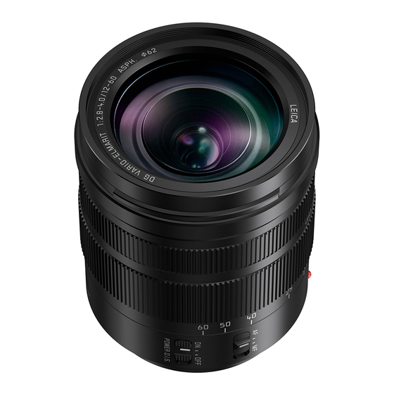
Interchangeable Lens for Digital Camera
H-ES12060PP
Model No.
H-ES12060E
H-ES12060GK
© Panasonic Corporation 2017 Unauthorized copying and distribution is a violation of law.
file:///C|/U...emp/Rar$EXa0.019/viewing/SGML_VIEW_DATA/ALL/H-ES12060PP/SVC/DSC1702007CE/doc/DSC1702007CE_cvr.xml[11/12/2018 10:33:20 AM]
ORDER NO.DSC1702007CE
B26
Advertisement
Table of Contents

Related Manuals for Panasonic H-ES12060PP


Summary of Contents for Panasonic H-ES12060PP
- Page 1 ORDER NO.DSC1702007CE Interchangeable Lens for Digital Camera H-ES12060PP Model No. H-ES12060E H-ES12060GK © Panasonic Corporation 2017 Unauthorized copying and distribution is a violation of law. file:///C|/U...emp/Rar$EXa0.019/viewing/SGML_VIEW_DATA/ALL/H-ES12060PP/SVC/DSC1702007CE/doc/DSC1702007CE_cvr.xml[11/12/2018 10:33:20 AM]...
-
Page 2: Safety Precautions
1 Safety Precautions 1.1 Information for Your Safety file:///C|/Users/n.shetabi/AppData/Local/Temp/Rar$EXa0.019/viewing/SGML_VIEW_DATA/ALL/H-ES12060PP/SVC/DSC1702007CE/doc/DSC1702007CE_01.xml[11/12/2018 10:35:19 AM]... -
Page 3: Cautions For Use
1.2 Cautions for use file:///C|/Users/n.shetabi/AppData/Local/Temp/Rar$EXa0.019/viewing/SGML_VIEW_DATA/ALL/H-ES12060PP/SVC/DSC1702007CE/doc/DSC1702007CE_01.xml[11/12/2018 10:35:19 AM]... - Page 4 file:///C|/Users/n.shetabi/AppData/Local/Temp/Rar$EXa0.019/viewing/SGML_VIEW_DATA/ALL/H-ES12060PP/SVC/DSC1702007CE/doc/DSC1702007CE_01.xml[11/12/2018 10:35:19 AM]...
-
Page 5: Service Navigation
2. Once "LENS MAIN UNIT" (Ref. 220) is confrmed as defective, place order "LENS Unit" (Ref. 200) and replace SHADING FRAME (Ref. 210), to maintain Serial number of owner's original lens. Fig. 1-1 3. No adjustment is required when replacing the part mentioned on Fig.1-1. But, when tighten the concerned screws,apply proper torque file:///C|/U...emp/Rar$EXa0.019/viewing/SGML_VIEW_DATA/ALL/H-ES12060PP/SVC/DSC1702007CE/doc/DSC1702007CE_02.xml[11/12/2018 10:36:27 AM]... - Page 6 "6. Disassembly and Assembly Instruction" section. file:///C|/U...emp/Rar$EXa0.019/viewing/SGML_VIEW_DATA/ALL/H-ES12060PP/SVC/DSC1702007CE/doc/DSC1702007CE_02.xml[11/12/2018 10:36:27 AM]...
- Page 7 3 Specifcations 3.1 Specifcations (Rated) file:///C|/U...emp/Rar$EXa0.019/viewing/SGML_VIEW_DATA/ALL/H-ES12060PP/SVC/DSC1702007CE/doc/DSC1702007CE_03.xml[11/12/2018 10:38:02 AM]...
- Page 8 3.2 Accessories file:///C|/U...emp/Rar$EXa0.019/viewing/SGML_VIEW_DATA/ALL/H-ES12060PP/SVC/DSC1702007CE/doc/DSC1702007CE_03.xml[11/12/2018 10:38:02 AM]...
-
Page 9: Location Of Controls And Components
4 Location of Controls and Components file:///C|/U...emp/Rar$EXa0.019/viewing/SGML_VIEW_DATA/ALL/H-ES12060PP/SVC/DSC1702007CE/doc/DSC1702007CE_04.xml[11/12/2018 10:38:55 AM]... - Page 10 file:///C|/U...emp/Rar$EXa0.019/viewing/SGML_VIEW_DATA/ALL/H-ES12060PP/SVC/DSC1702007CE/doc/DSC1702007CE_04.xml[11/12/2018 10:38:55 AM]...
-
Page 11: Service Fixture And Tools
The repair quality is considered, and it is recommended working in the environment of satisfed clean level less than class 10,000 (Federal Standard 209D). [NOTE] Work in the environment of satisfed clean level less than class 10,000 (Federal Standard 209D) for cleaning the inside of the lens. file:///C|/U...emp/Rar$EXa0.019/viewing/SGML_VIEW_DATA/ALL/H-ES12060PP/SVC/DSC1702007CE/doc/DSC1702007CE_05.xml[11/12/2018 10:42:29 AM]... -
Page 12: Disassembly Flow Chart
1. When installing the screws, be sure to use the torque driver (RFKZ0542) and tighten the screws with specifed torque, mentioned on the following. Caution Keep covering the lens unit with Lens caps (front & rear), other than necessary cases. 6.2 Disassembly Flow Chart 6.3 Disassembly Procedure file:///C|/U...emp/Rar$EXa0.019/viewing/SGML_VIEW_DATA/ALL/H-ES12060PP/SVC/DSC1702007CE/doc/DSC1702007CE_06.xml[11/12/2018 10:43:46 AM]... - Page 13 6.3.2 Removal of the Filter Ring 1. Remove 3 screws (A) and the Filter Ring. 6.3.3 Removal of the Shading Frame 1. Remove 2 screws (B) and the Shading Frame. 6.3.4 Removal of the L Mount Unit file:///C|/U...emp/Rar$EXa0.019/viewing/SGML_VIEW_DATA/ALL/H-ES12060PP/SVC/DSC1702007CE/doc/DSC1702007CE_06.xml[11/12/2018 10:43:46 AM]...
- Page 14 2. Disconnect the Connector of the Lens P.C.B.. 3. Remove 3 screws (E) and the Rear Frame Unit. 6.3.6 Removal of the Lens P.C.B. Unit and the L Mount Contact Unit 1. Disconnect the 4 Connectors of the Lens P.C.B.. file:///C|/U...emp/Rar$EXa0.019/viewing/SGML_VIEW_DATA/ALL/H-ES12060PP/SVC/DSC1702007CE/doc/DSC1702007CE_06.xml[11/12/2018 10:43:46 AM]...
- Page 15 2. Remove 2 screws (F) and the Lens P.C.B. with the L Mount Contact Unit. 3. Remove the L Mount Connect Unit from Lens P.C.B.. 6.3.7 Removal of the Rear Frame Earth Spring 1. Remove screw (G) and the Rear Frame Earth Sprig. file:///C|/U...emp/Rar$EXa0.019/viewing/SGML_VIEW_DATA/ALL/H-ES12060PP/SVC/DSC1702007CE/doc/DSC1702007CE_06.xml[11/12/2018 10:43:46 AM]...
-
Page 16: Assembly Flow Chart
6.3.8 Removal of the Zoom Drive Pin and the Zoom Ring Unit 1. Remove screw (H) and the Zoom Drive Pin. 2. Remove the Zoom Ring Unit. 6.4 Assembly Flow Chart file:///C|/U...emp/Rar$EXa0.019/viewing/SGML_VIEW_DATA/ALL/H-ES12060PP/SVC/DSC1702007CE/doc/DSC1702007CE_06.xml[11/12/2018 10:43:46 AM]... -
Page 17: Assembly Procedure
1. Install the Zoom Ring Unit and the Zoom Drive Pin. 2. Tighten screw (H) by using the torque driver with specifed torque. 6.5.2 Installation of the Rear Frame Earth Spring 1. Install the Rear Frame Earth Spring. file:///C|/U...emp/Rar$EXa0.019/viewing/SGML_VIEW_DATA/ALL/H-ES12060PP/SVC/DSC1702007CE/doc/DSC1702007CE_06.xml[11/12/2018 10:43:46 AM]... - Page 18 6.5.3 Installation of the L Mount Contact Unit and the Lens P.C.B. 1. Connect FPC of the Mount Connect Unit to connector. 2. Installation the Main P.C.B. with the Mount Contact Unit. 3. Tighten 2 screws (F) by using the torque driver with specifed torque. file:///C|/U...emp/Rar$EXa0.019/viewing/SGML_VIEW_DATA/ALL/H-ES12060PP/SVC/DSC1702007CE/doc/DSC1702007CE_06.xml[11/12/2018 10:43:46 AM]...
- Page 19 6.5.4 Installation of the Rear Frame Unit and the Dustproof Rubber 1. Install the Rear Frame Unit and the Dustproof Rubber. 2. Tighten 3 screws (E) in numerical order by using the torque driver with specifed torque. file:///C|/U...emp/Rar$EXa0.019/viewing/SGML_VIEW_DATA/ALL/H-ES12060PP/SVC/DSC1702007CE/doc/DSC1702007CE_06.xml[11/12/2018 10:43:46 AM]...
- Page 20 2. Tighten screw (C) and 3 screws (D) in numerical order by using the torque driver with specifed torque. 6.5.6 Installation of the Shading Frame 1. Install the Shading Frame. 2. Tighten 2 screws (B) in numerical order by using the torque driver with specifed torque. file:///C|/U...emp/Rar$EXa0.019/viewing/SGML_VIEW_DATA/ALL/H-ES12060PP/SVC/DSC1702007CE/doc/DSC1702007CE_06.xml[11/12/2018 10:43:46 AM]...
- Page 21 Use new one, do not use the one which is removed. Double-stick tape sticks to the Decoring Unit of the repair part. Remove the old double-stick tape from the Filter Ring. 2. After installing the Decoring Unit, use a soft cloth to ress it into place. file:///C|/U...emp/Rar$EXa0.019/viewing/SGML_VIEW_DATA/ALL/H-ES12060PP/SVC/DSC1702007CE/doc/DSC1702007CE_06.xml[11/12/2018 10:43:46 AM]...
- Page 22 file:///C|/U...emp/Rar$EXa0.019/viewing/SGML_VIEW_DATA/ALL/H-ES12060PP/SVC/DSC1702007CE/doc/DSC1702007CE_06.xml[11/12/2018 10:43:46 AM]...
-
Page 23: Maintenance
1. Blow off the dust on the Lens glass surface with the Blower, gently. (Do not blow strongly.) 2. Wipe out the dirt on the Lens glass surface with Lens Cleaning Kit (VFK1900BK) if necessary. (Consult the instruction sheet which is included in the Lens Cleaning Kit in details.) file:///C|/U...emp/Rar$EXa0.019/viewing/SGML_VIEW_DATA/ALL/H-ES12060PP/SVC/DSC1702007CE/doc/DSC1702007CE_07.xml[11/12/2018 10:45:30 AM]... -
Page 24: Exploded View And Replacement Parts List
Please click the radio button for "Diagrams II / Parts List" on the menu bar in XML Service Manual. If you want to print, please click the icon button for "Print" on the icon bar and select the item. file:///C|/U...emp/Rar$EXa0.019/viewing/SGML_VIEW_DATA/ALL/H-ES12060PP/SVC/DSC1702007CE/doc/DSC1702007CE_08.xml[11/12/2018 10:47:11 AM]... - Page 25 Print Parts List Model No. : H-ES12060PP/E/GK Frame and Casing Section Model No. : H-ES12060PP/E/GK Packing Parts and Accessories file:///C|/U...al/Temp/Rar$EXa0.608/viewing/SGML_VIEW_DATA/ALL/H-ES12060PP/SVC/DSC1702007CE/mec2/en/html/print_all.htm[11/12/2018 2:38:41 PM]...
- Page 26 Print Parts List Model No. : H-ES12060PP/E/GK Parts List Ref. Change Safety Part No. Part Name & Description Q'ty Remarks SYF0083 LENS CAP VFC4605-B LENS REAR CAP VPF1475 LENS BAG 1ZE4Z260Z LENS HOOD OPERATING INSTRUCTIONS (ENGLISH/CA file:///C|/U...al/Temp/Rar$EXa0.608/viewing/SGML_VIEW_DATA/ALL/H-ES12060PP/SVC/DSC1702007CE/mec2/en/html/print_all.htm[11/12/2018 2:38:41 PM]...
- Page 27 SCREW B205 VHD2011 SCREW B206 VHD2073 SCREW B207 VHD2073 SCREW B208 VHD2296 SCREW B209 VHD2296 SCREW B210 VHD2296 SCREW B211 VHD2299 SCREW B212 VHD2299 SCREW B213 VHD2299 SCREW B214 VHD2298 SCREW B215 VHD2246 SCREW B216 VHD2246 SCREW file:///C|/U...al/Temp/Rar$EXa0.608/viewing/SGML_VIEW_DATA/ALL/H-ES12060PP/SVC/DSC1702007CE/mec2/en/html/print_all.htm[11/12/2018 2:38:41 PM]...