Table of Contents
Advertisement
Quick Links
Advertisement
Table of Contents

Related Manuals for SATO CT4-LX


Summary of Contents for SATO CT4-LX
- Page 1 FX3-LX...
-
Page 2: Table Of Contents
Table of Contents Table of Contents Before You Start......................8 About This Manual..........................8 Safety Precautions..........................9 Precautions for Installation and Handling..................14 Select a Safe Location........................14 Power Supply..........................15 Printing............................16 Regulatory Approval......................... 17 Environmentally Hazardous Materials....................20 Copyrights............................21 Limitation of Liability......................... 22 Trademarks............................ - Page 3 Getting Started......................73 Installation Space..........................73 Front View........................... 73 Side View.............................74 Bottom View..........................75 Powering On/Off the Product......................76 Connecting the AC Adapter and the Power Cord..............76 Powering On the Product......................77 Powering Off the Product......................79 Initial Setup (Startup Guide)......................81 Startup Guide Flow........................
- Page 4 Table of Contents Conditions That Trigger Ribbon Near End (Thermal Transfer Only)........161 Various Settings of the Product................162 The [SETTINGS] Menu........................162 [Printing] Menu.......................... 163 [Media Type].........................163 [Label Length]........................163 [Label Width]........................164 [Auto Measure]........................164 [Printing Mode]........................165 [Ribbon Near End]....................... 165 [Speed]..........................
- Page 5 [Profiles]..........................269 [Service]..........................270 [Factory]..........................271 [Wi-Fi Site Survey]....................... 271 [Install Certificates]....................... 271 [Delete Certificates]......................272 [Clone]..........................272 [AutoClone Setting]......................273 [Startup Guide]........................274 [Information] Menu........................275 [Help]............................ 275 [Build Version]........................278 [Applications]........................278 [Installation Log]........................278 [Print Module]........................279 [Sensor Module]........................279 [FPGA Version]........................279 [Counters]..........................
- Page 6 Replacing the Print Head......................445 Replacing the Platen Roller...................... 448 Replacing the Optional Linerless Platen Roller................ 450 Operating the Notification Screen of the SOS (SATO Online Services) On-Demand Mode (SOS users only)............................452 SOS (SATO Online Services) Application (SOS users only)............454...
- Page 7 When You Are in Trouble..................455 When an Error Message Appears....................455 Appearance of Error Messages and Operating Procedure When SOS (SATO Online Services) Is Enabled (SOS users only)......................513 Contact Information for When You Are in Trouble.................514 Product Specifications...................515 Hardware............................
-
Page 8: Before You Start
About This Manual Thank you for purchasing the SATO CT4-LX (hereafter referred to as "the product"). This manual supplies basic information on how to operate the CT4-LX. Read the manual carefully to understand each function of the CT4-LX before operation. -
Page 9: Safety Precautions
Safety Precautions This topic describes how to use the product safely. Be sure to read the following information carefully before using the product. Pictographic Symbols This operator manual and the product labels use a variety of pictographic symbols. These symbols emphasize the safe and correct use of the product and to prevent injury to others and property damage. - Page 10 If the product or AC adapter is dropped or breaks, immediately power off the product, unplug the power cord from the outlet, and contact your SATO reseller or technical support. Using the product in one of these conditions could result in a fire or electric shock.
- Page 11 Do not operate with wet hands • Do not disassemble or modify the product or the AC adapter. Doing so could result in a fire or electric shock. Ask your SATO reseller or technical support to conduct internal inspections, adjustments, and repairs.
- Page 12 Safety Precautions Do not disassemble the product and the AC adapter • Do not use cleaning fluids other than the ones supplied with the product or recommended by us. • The cleaning fluid is to be strictly kept away from the fire. Never apply heat or place it in the fire.
- Page 13 • To replace the print head, follow the procedure in the Operator Manual. If the Operator Manual does not contain this procedure, avoid trying to replace it on your own terms, and contact your SATO reseller or technical support. •...
-
Page 14: Precautions For Installation And Handling
Select a Safe Location Precautions for Installation and Handling Select a Safe Location Product operations can be affected by the product's environment. Refer to the following instructions regarding how to install and handle the product. Install the product on a surface that is flat and level. Installing the product on a surface that is tilted, and not flat, may reduce the print quality. -
Page 15: Power Supply
Power Supply Product operations can be affected by the product's environment. Refer to the following instructions regarding how to install and handle the product. The product requires an AC power supply. Be sure to connect the product to an AC power supply. Supply a stable source of electricity to the product. -
Page 16: Printing
(the print speed, the print darkness, etc.). Please sufficiently test the product in your usage environment, and use it with the optimal combination. If anything is unclear, or if you have any questions, contact your SATO sales representative or reseller. -
Page 17: Regulatory Approval
Regulatory Approval FCC Warning You are cautioned that changes or modifications not expressly approved by the party responsible for compliance could void your authority to operate the equipment. This device complies with Part 15 of the FCC Rules. Operation is subject to the following two conditions: (1) this device may not cause harmful interference, and (2) this device must accept any interference received, including interference that may cause undesired operation. - Page 18 Regulatory Approval installed and operated keeping the radiator at least 20 cm or more away from person’s body (excluding extremities: hands, wrists, feet and ankles). Le présent appareil est conforme aux CNR d’Industrie Canada applicables aux appareils radio exempts de licence. L’exploitation est autorisée aux deux conditions suivantes : •...
- Page 19 Disposal of Old Electrical & Electronic Equipment (Applicable in the European Union and other European countries with separate collection systems) A product marked with this symbol on itself or on its packaging shall not be treated as household waste. Instead it shall be handed over to an appropriate collection point for the recycling of electrical and electronic equipment in accordance with local regulations.
-
Page 20: Environmentally Hazardous Materials
Environmentally Hazardous Materials Environmentally Hazardous Materials RoHS Directive This product is in conformity with RoHS Directive 2011/65/EU on the Restriction of the Use of Certain Hazardous Substances in Electrical and Electronic Equipment. Compliance Status of REACH Regulation (1) Status of registered chemical substances No chemical substances are intentionally emitted, nor are there any chemical substances that are registered with the European Chemicals Agency. -
Page 21: Copyrights
Copyrights Any unauthorized reproduction of the contents of this document, in part or whole, is strictly prohibited. © 2020 SATO Corporation. All rights reserved. -
Page 22: Limitation Of Liability
Specifications and contents in this document are subject to change without notice. • Be sure to perform a virus check on the USB memory before connecting it to the product. SATO Corporation shall not be held responsible for any product malfunctions caused by a virus spread via USB memory. -
Page 23: Trademarks
Trademarks • The following are registered trademarks of SATO Holdings Corporation and its subsidiaries in Japan, the U.S. and other countries. ◦ SATO ◦ Stylized SOS (SATO Online Services) • ® NiceLabel is a trademark or registered trademark of Euro Plus d.o.o. -
Page 24: What You Can Do With This Product
Features of the Product What You Can Do with This Product Features of the Product CT4-LX is a compact labeling system with versatile functions. Its main features are as follows: • Very easy-to-use 4.3-inch color touch panel • Supports various communication interfaces •... -
Page 25: Various Ways To Output
Labels can be easily output by using software, such as the NiceLabel series. • NiceLabel series This software has multiple functions and is easy to operate so you can create and print labels with richly versatile layouts. • For details of the products, contact your SATO sales representative. -
Page 26: Outputting And Controlling With Dedicated Command
In addition, you can print characters, barcodes, and graphics in various styles by combining multiple SBPL commands. There are many functions for modifying the printed items, such as enlarging fonts, specifying a print direction, ruled line, and black and white reverse printing. For programming references, contact your SATO sales representative or technical support. -
Page 27: Outputting With Standalone (Aep) Applications
Outputting with Standalone (AEP) Applications Labels can be printed by running standalone (AEP) applications within the product. • For details of the standalone applications, contact your SATO sales representative. • AEP does not support RFID. -
Page 28: Basic Information
Bundled Accessories After unpacking the product, make sure that you have all the bundled accessories. If there are any missing items, contact the SATO reseller where you purchased the product. • Printed materials (Quick Guide, Safety Instructions, Global Warranty Program leaflet, Product Information Download, Declaration of Conformity) •... - Page 29 • Keep the packaging box and cushioning material after installing the product. You can pack the product into the packaging box to ship it to have repairs done.
-
Page 30: Optional Devices
Wireless LAN/Bluetooth kit Wireless LAN and Bluetooth interfaces can be used. RTC (calendar) kit A calendar system for printing the date and time on a label to output. • For more details about the optional devices, contact your SATO sales representative. -
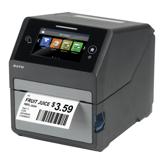
Page 31: Parts Identification
Parts Identification Front View (1) LED indicator (2) NFC antenna location (3) LCD/Touch panel (4) Media discharge outlet (5) Cover open latch (Power/Home) button To power on the product, press the (Power/Home) button until the LED lights blue. While the product is powered on, press the (Power/Home) button to switch to the Home screen. - Page 32 • Be sure to perform a virus check on the USB memory before connecting it to the product. SATO Corporation shall not be held responsible for any product malfunctions caused by a virus spread via USB memory. (4) LAN connector Use to connect the product to a network using the LAN interface.
- Page 33 USB memory. • Be sure to perform a virus check on the USB memory before connecting it to the product. SATO Corporation shall not be held responsible for any product malfunctions caused by a virus spread via USB memory.
- Page 34 Parts Identification • The size of the USB memory that can be connected inside the product is as follows: ◦ Length: under 68 mm (2.68") (excludes the metal part of the connector) ◦ Width: under 27.6 mm (1.09") ◦ Thickness: under 8.6 mm (0.34") (3) Engraved Indicated by the (ribbon cover open) marks on the combined direct thermal/thermal transfer...
-
Page 35: Using The Operator Panel
Using the Operator Panel LED Indicator The LED indicator lights to show the current status of the product. The LED indicator shows the following states of the product. LED Indicator Color/Status Description Blue/Lit Online mode Blue/Blinking Power supply is on Power off or Offline mode Red/Lit Product error, or during the powering off... -
Page 36: Operating The Touch Panel
Operating the Touch Panel Operating the Touch Panel This topic explains the basic operations of the touch panel. Lightly touch the screen, and then release your finger. Long touch Touch the screen for more than 1 second before removing your finger. Swipe/Slide With your finger lightly touching the screen, move it across the screen to the desired direction. - Page 37 Quickly brush your finger up, down, left, or right against the screen.
-
Page 38: Operations In The Home Screen
(1) Enters the Settings mode. Various settings of the product can be operated here. (2) Displays the setting menus of the SATO RF Analyze function on an RFID model. This function allows you to measure RFID tags and easily set conditions to consistently write and read the tags. -
Page 39: Operations In Online/Offline Mode
Operations in Online/Offline Mode Online mode In Online mode, you can execute the print job. In the default settings, the product powers on in Online mode. If the Home screen is displayed, press the (Power/Home) button to switch to Online mode. (1) Change to Offline mode. - Page 40 Operations in Online/Offline Mode (2) Shows the Adjustments mode when the print job is paused. Shows the Settings mode when there are no print jobs. (3) Feed the media. (4) Change to Online mode. Displays Shared in Online/Offline Mode The following information appears in the upper left of the screen. (1) Resolution of the product (2) Current printer language You can set the printer language in the [Applications] >...
-
Page 41: Operations In The Panel That Is Displayed By Swiping The Screen
Operations in the Panel That Is Displayed by Swiping the Screen You can adjust the volume and brightness in the panel that is displayed by swiping the screen. To open the panel, swipe down from the top of the screen. (1) Slide the bar to adjust the brightness of the LCD. -
Page 42: Status Icon
Status Icon Status Icon The icons on the status bar of the display show the product status. (1) Status bar Communication Interface Status Icon Description Bluetooth is enabled but not connected. Bluetooth is enabled and connected. Bluetooth startup failed. Network link is enabled but not connected. Network link is enabled and connected. - Page 43 Icon Description NFC is disabled. NFC is enabled and connected. Not connected to the NTP time server. Wi-Fi is authenticated, but not connected. Wi-Fi startup failed. Wi-Fi is connected. Signal Level 1 Wi-Fi is connected. Signal Level 2 Wi-Fi is connected. Signal Level 3 Wi-Fi is connected.
- Page 44 RFID mode is enabled. RFID mode is enabled, but the system is defective. Or the SATO RF Analyze (SRA) motor unit is not operating correctly. Standard code is disabled. The On-Demand mode of the SOS (SATO Online Services) is enabled.
- Page 45 Icon Description The periodic notification in the On-Demand mode of SOS as set previously has arrived. Scan the QR code and send the information to the SOS cloud. LAN or Wi-Fi is connected, but an IP address has not been assigned to the product.
- Page 46 Status Icon Icon Description Defective print head is detected. Replace the print head. Incompatible print head is detected. Replace the print head. Maintenance Status When [Notifications] is enabled, icons notify you at set periods about cleaning and replacing parts. Icon Description Clean the print head or platen roller.
-
Page 47: Operations When Errors Occur
• Select whether to continue, stop, or retry the process. • When SOS (SATO Online Services) is enabled, scan the QR code or the NFC mark on the product, or contact support by telephone. • The available operations vary, depending on the situation. -
Page 48: Adjusting The Print Settings During Printing
Adjusting the Print Settings During Printing Adjusting the Print Settings During Printing Follow the procedure below to adjust the print position, print darkness, print speed, and the label top sensor during printing. 1. Tap [OFFLINE] or press the (Power/Home) button. Printing stops and the product switches to Offline mode. - Page 49 4. Select an item and adjust the setting. 5. Tap or press the (Power/Home) button. Returns to the Offline screen. 6. Tap [ONLINE] or press the (Power/Home) button. The product switches to Online mode, and printing restarts using the adjusted settings. •...
-
Page 50: Canceling The Print Job
Canceling the Print Job Canceling the Print Job Cancel the print job according to the following procedure. When the print job is canceled, the data stored in the receive buffer of the product is also deleted. 1. Tap [OFFLINE] or press the (Power/Home) button. - Page 51 3. Tap The print job is canceled.
-
Page 52: Guidance Videos
Guidance Videos Guidance Videos The product contains guidance videos that are shown on the display for visual reference of the product's operations. -
Page 53: List Of The Guidance Videos
List of the Guidance Videos The product contains the guidance videos for visual reference of product operations. The onboard guidance videos are as follows: Guidance video Show video from Error screen Startup Guide [Information] Menu Media roll loading (standard Possible Possible specifications) Media roll loading (cutter... - Page 54 List of the Guidance Videos Guidance video Show video from Error screen Startup Guide [Information] Menu Fan-fold media replacement Possible Possible (standard specifications) Fan-fold media replacement Possible Possible (cutter specifications) Ribbon replacement Possible Possible Print head replacement Possible Possible Platen roller replacement Possible (standard specifications) Platen roller replacement...
-
Page 55: Playing The Guidance Video From The Error Screen
Playing the Guidance Video from the Error Screen Play the guidance video from the error screen and resolve the error by following the procedure of the video. 1. In the error screen, tap [HELP]. The guidance video starts. • The media selection screen appears when a paper end error occurs. Tapping the type of media you want to load starts the guidance video. -
Page 56: Getting Access To The Guidance Video In Online Mode
Getting Access to the Guidance Video in Online Mode Getting Access to the Guidance Video in Online Mode When in the Online mode, play the guidance video according to the following procedure. 1. Tap [OFFLINE] in Online mode. The product switches to Offline mode. 2. - Page 57 You can switch the screen by tapping or sliding the screen to the left or right. 5. Tap [Help]. The guidance video list appears. 6. Tap the video for playback. The guidance video starts.
-
Page 58: Operating The Guidance Video
Operating the Guidance Video Operating the Guidance Video Tap the screen as the video is playing to display the icons for operating the video. (1) Tap to perform continuous playback. When this function is enabled, the icon changes to blue. (2) Playback or pause the video. -
Page 59: Settings Mode
Settings Mode In the Settings mode, you can set the product's various settings. The topics here explain how to operate the Settings mode. -
Page 60: Settings Mode Menus
Settings Mode Menus Settings Mode Menus There are the following menus in the Settings mode and each menu contains many layers of submenus. Menu Description Printing Menu Access the settings related to printing. Interface Menu Access the settings related to the interfaces. Applications Menu Access the settings related to the printer's command. -
Page 61: Changing To The Settings Mode
Changing to the Settings Mode The Settings mode appears when no print jobs remain in the product. Change the product to the Settings mode according to the following procedure: 1. Tap [OFFLINE] in Online mode. The product switches to Offline mode. 2. - Page 62 Changing to the Settings Mode The product enters Settings mode. • You can also enter the Settings mode from the Home screen. Press the (Power/Home) button while in Online or Offline mode to show the Home screen. • To exit the Settings mode, press the (Power/Home) button to show the Home screen, or tap to return to the previous screen.
-
Page 63: Logging In To/Logging Out Of The Settings Mode
Logging In to/Logging Out of the Settings Mode The Settings mode logs in and logs out by the following procedure, if the password is enabled. • If the password is enabled, input the password when entering the Settings mode. When logged in to the Settings mode, [LOG OUT] appears on the bottom left of the screen. •... -
Page 64: Settings Mode Operations
Settings Mode Operations Settings Mode Operations Each menu in the Settings mode contains many layers of submenus, as follows: The operations differ depending on the following type of setting items. Display image Description Select/clear the checkbox by tapping it to enable/ disable the function. - Page 65 Display image Description Input values from the on-screen keyboard. to confirm the setting. to execute items. to a test print or print a list of settings. to delete items. Items with no pencil icon are read-only items.
-
Page 66: Setting Value Input
Setting Value Input Setting Value Input This topic describes the character and number input on the setting screen. • You can also input characters and numbers from a USB keyboard by connecting it to the product. • Character Input • Numeric Input •... - Page 67 • Numeric Input (1) The numbers you enter are displayed in the text box. For passwords and other secret information, tap to display what has been input. (2) Tap the on-screen keyboard to input numbers. (3) Change the input mode. (4) Delete the number to the left of the cursor indicated in the text box.
-
Page 68: Memory Of The Product
Register user data such as fonts, external characters, or graphics • Be sure to perform a virus check on the USB memory before connecting it to the product. SATO Corporation shall not be held responsible for any product malfunctions caused by a virus spread via USB memory. •... -
Page 69: Connecting The Usb Memory Inside The Product
Connecting the USB Memory Inside the Product You can do automatically back up the product's setting information by connecting a USB memory for the auto-clone function into the USB connector (Type A) inside the product. Also, user data, such as fonts, external characters, and graphics on the USB, can be registered to the product. - Page 70 Connecting the USB Memory Inside the Product The parts (3) are indicated by the (ribbon cover open) marks on the combined direct thermal/ thermal transfer model. 3. Remove the screw (4) from the underside of the top cover, and then open the USB memory cover (5).
- Page 71 4. Insert the USB memory into the USB connector (6). 5. Close the USB memory cover, and secure it with the screw. 6. Close the cover (7). 7. Close the top cover. Push both ends of the top cover, and close it firmly until it clicks.
- Page 72 Connecting the USB Memory Inside the Product • When closing the top cover, be careful not to pinch your fingers. • icon is shown in the status bar.
-
Page 73: Getting Started
Getting Started Installation Space Front View Keep sufficient space around the product. The dimensions of the front of the product are as follows: The figure below shows the standard model. : Leave open 150 mm (5.91") or more. -
Page 74: Side View
Side View Side View Make sure that there is sufficient space around the product so that the top cover can be fully opened when operating or cleaning the product, or replacing consumables. Make sure that there is sufficient space on the rear side of the product so that no stress is applied to the power cord or cables connected to the product. -
Page 75: Bottom View
Bottom View The dimensions of the bottom of the product are as follows: The figure below shows the standard model. -
Page 76: Powering On/Off The Product
Make sure that the AC voltage of your region is in the range of AC 100 - 240 V, 50 - 60 Hz. If your local voltage is not in the stated range, contact your SATO reseller or technical support. -
Page 77: Powering On The Product
Powering On the Product • Do not connect or disconnect the power cord while your hands are wet. Doing so could cause an electric shock. 1. Press the (Power/Home) button (1) of the operator panel until the LED indicator (2) lights blue, and then remove your finger. The Online screen appears. - Page 78 Powering On the Product • When you power on the product for the first time after purchase or reboot after resetting the settings, the startup guide appears. You can easily set the printing preferences on the product by following the on-screen instructions. •...
-
Page 79: Powering Off The Product
Powering Off the Product • Do not connect or disconnect the power cord while your hands are wet. Doing so could cause an electric shock. • Do not power off the product during operation, such as when printing or updating. Doing so could cause a malfunction of the product. - Page 80 Powering Off the Product 3. Tap • You can power on/off the product from the main power source that supplies the product with power by enabling [Start on AC] on the [System] menu.
-
Page 81: Initial Setup (Startup Guide)
Initial Setup (Startup Guide) The topics here explain how to complete the startup guide that appears when you power on the product for the first time after purchase. -
Page 82: Startup Guide Flow
Startup Guide Flow Startup Guide Flow The startup guide is a function to help you through the initial product settings (language selection, date and time settings, loading media, etc.). You can cancel the startup guide and perform the configuration later from the menu. •... - Page 83 4. Tap the city to set for the time zone. (Appears if you have enabled the NTP function or installed the optional RTC kit.) to reselect the region. 5. Tap the unit to use. The options are as follows: ◦ ◦...
- Page 84 Startup Guide Flow 7. Tap to set the current time, and then tap (Appears if you have disabled the NTP function and installed the optional RTC kit.) • The time is set in the 24-hour format. When the confirmation screen appears, tap to confirm the settings.
- Page 85 9. Tap the sensor type for detecting the media. [None] Disable the media sensor. [Gap] Select when using the media of Gap type. Use the transmissive sensor. [I-Mark] Select when using the media of I-mark type. Use the reflective sensor. •...
- Page 86 Startup Guide Flow • [Fanfold] is not displayed if the optional dispenser unit is installed. • [Install Ribbon] is displayed only if [Use Ribbon] is selected for [Printing Mode] on the combined direct thermal/thermal transfer model. 11. When you have finished loading the media and ribbon, tap on the video's screen to stop the video.
-
Page 87: Startup Guide Cancelation
Startup Guide Cancelation You can cancel the startup guide at any time. 1. Press the (Power/Home) button while doing settings in the startup guide. The screen to confirm whether or not to show the startup guide again appears. 2. Select whether or not to show the startup guide during the next startup. Tap [CANCEL] to return to the startup guide setting without canceling it. -
Page 88: Manually Setting The Print Mode
Manually Setting the Print Mode Manually Setting the Print Mode You can change the print mode of the product according to product specification and its usage. When [Auto-mode] is enabled, the print mode is set automatically according to the installed options. You can manually set the print mode if you disable [Auto-mode]. - Page 89 4. Disable [Auto-mode]. 5. Tap [Print Mode]. 6. Select the print mode. • Changing the print mode may link to and change [Sensor Type] and [Backfeed]. After changing the settings, confirm that the settings have become compatible with the media you are using. •...
-
Page 90: Connecting The Product To A Computer
Connecting the Product to a Computer Connecting the Product to a Computer This section explains how to connect the product to a computer, and how to install the printer driver and the All-In-One Tool. -
Page 91: Procedure For Connecting The Product To A Computer
Procedure for Connecting the Product to a Computer The product supports various interfaces and can be connected to a computer in an optimum way for your environment. When you have installed the printer driver to the computer, the data created with the computer (documents and illustrations) can be printed to a label through easy operations. -
Page 92: Connecting Interfaces
Available Interfaces Connecting Interfaces Available Interfaces The product supports the following interfaces. • A product connected with multiple interface cables can continue to operate when receiving data. However, you cannot receive data from more than one interface at a time. Normally, do not use multiple interfaces at a time. •... -
Page 93: Usb Interface Connection (Standard)
(3) Wireless LAN/Bluetooth (optional) (4) RS-232C (option) (5) NFC • The NFC interface supports the handover function that simplifies the Bluetooth/Wi-Fi connection setup with Android devices. In addition, the NFC interface can be used for changing product settings with an Android device while the product is powered off and the power cord is not connected. -
Page 94: Nfc Interface Connection (Standard)
NFC Interface Connection (Standard) The USB interface is selected after connecting the USB cable to the computer and the product, and powering on the product while the computer is turned on. • If the product is powered on without installing the printer driver, Windows' Plug & Play runs. -
Page 95: Lan Interface Connection (Standard)
• If it does not communicate well, shift the Android device to the front, back, left and right, and then hold it up again. • For the operation of the NFC for the Android device, refer to the user manual for the Android device. -
Page 96: Rs-232C Interface Connection (Optional)
RS-232C Interface Connection (Optional) • To use the printer driver, the communication protocol must be set to Status4. (The initial value of the communication protocol for the product's LAN interface is Status4 ENQ.) RS-232C Interface Connection (Optional) Check if the RS-232C kit is attached to the product. Connect the interface cable when the product is powered off. -
Page 97: Wireless Lan Interface Connection (Optional)
• When not using an RS-232C cable, put the connector cover that is provided onto the RS-232C connector. • The interface settings of the computer can be confirmed by the following. In the Device Manager, right-click [Ports (COM & LPT)] > [Communications Port (COM1)] and select [Properties]. -
Page 98: Bluetooth Interface Connection (Optional)
Bluetooth Interface Connection (Optional) The IP address of the product can be set through the product's [Wi-Fi] menu or the All-In-One Tool. • To use the printer driver, the communication protocol must be set to Status4. (The initial value of the communication protocol for the product's wireless LAN interface is Status4 ENQ.) •... -
Page 99: Configuring The Interface Settings
Configuring the Interface Settings Interface Setting Methods Configure the interface settings of the product according to the communication conditions of the connected network and computer. You can set the interface settings of the product doing either of the following. • Set from the Settings mode of the product •... -
Page 100: Configuring The Interface Settings Using The All-In-One Tool
Installing the All-In-One Tool When you use the All-In-One Tool, you can easily set and manage the product. Download the All-In-One Tool and All-In-One Tool Manual from your local SATO website https:// www.sato-global.com/drivers/redirect.html, and install the software to a computer. For the compatible... -
Page 101: Installing The Printer Driver
Installing the Printer Driver The printer driver is software that can send data created on the computer (documents and illustrations) to the product and print it to a label. Download and use the printer driver from your local SATO website https://www.sato-global.com/ drivers/redirect.html. -
Page 102: All-In-One Tool Features
All-In-One Tool Features When you add the product to the All-In-One Tool, you can easily set and manage the product. • For details of the All-In-One Tool, download and read the All-In-One Tool Manual from your local SATO website. https://www.sato-global.com/drivers/redirect.html... -
Page 103: Loading Media And Ribbon
Loading Media and Ribbon Media, Ribbon and Print Methods The product is available in two models, the direct thermal model and the combined direct thermal/ thermal transfer model. The media or ribbon to be used varies depending on the print method. Thermal transfer (combined direct thermal/thermal transfer model only) Prints using a ribbon. -
Page 104: Loading Media
Usable Media Loading Media Usable Media The product can print on the following types of media: • Media roll • Fan-fold media • Wristbands The product uses media sensors to detect I-marks or Gaps on the media in order to precisely print the content. -
Page 105: Wind Direction Of The Media
Wind Direction of the Media The media either winds face-out or face-in. Load the media with the print side facing up. Face-out Face-in The print side faces the outer side of the media. The print side faces the inner side of the media. (1) Print side... -
Page 106: Precautions For Loading The Media
Precautions for Loading the Media Precautions for Loading the Media Use our specified supply products for the product, for optimum print quality. • The print head and its surroundings are hot after printing. Be careful not to get burned. • Touching the edge of the print head with your bare hand could cause injury. -
Page 107: Loading The Media Roll
Loading the Media Roll • The print head and its surroundings are hot after printing. Be careful not to get burned. • Touching the edge of the print head with your bare hand could cause injury. 1. Press the cover open latch (1) to open the top cover (2). 2. - Page 108 Loading the Media Roll 3. Load the media roll. Load the media roll from above so the print side faces the print head (5). If the media roll is loaded correctly, the flaps (6) stand up. • There are two wind directions for the media. The illustration is for face-out media. 4.
- Page 109 • When closing the top cover, be careful not to pinch your fingers. • When the Label Waste Prevention function is enabled, an error occurs if the leading edge of the media extends too far from the media discharge outlet. Align the leading edge of the media with the media discharge outlet.
-
Page 110: Loading A Media Roll (When The Optional Dispenser Unit Is Installed)
Loading a Media Roll (When the Optional Dispenser Unit Is Installed) Loading a Media Roll (When the Optional Dispenser Unit Is Installed) This topic explains how to load media when [Dispenser] is selected in print mode while the optional dispenser unit is installed. If you have selected [Continuous] in print mode, the loading method is the same as the standard. - Page 111 3. While pulling the slide lever (5), move the right side media guide (6) to adjust the width of the media guide to match the width of the media. 4. Load the media roll. Load the media roll from above so the print side faces the print head (7). If the media roll is loaded correctly, the flaps (8) stand up.
- Page 112 Loading a Media Roll (When the Optional Dispenser Unit Is Installed) 5. Peel off about 20 cm (7.87") of the label, and pull the liner out under the left and right tabs (9). 6. Close the top cover. Push both ends of the top cover, and close it firmly until it clicks. •...
- Page 113 7. Pass the liner through the gap (opening) between the dispenser cover and the product out of the product , and close the dispenser cover 8. Pull the liner lightly so that the media does not sag. 9. Tap [FEED] to feed the media to the print start position.
- Page 114 Loading a Media Roll (When the Optional Dispenser Unit Is Installed) 10. Tap [ONLINE] to change the product to Online mode.
-
Page 115: Loading A Media Roll (When The Optional Cutter Unit Is Installed)
Loading a Media Roll (When the Optional Cutter Unit Is Installed) • The print head and its surroundings are hot after printing. Be careful not to get burned. • Touching the edge of the print head with your bare hand could cause injury. •... - Page 116 Loading a Media Roll (When the Optional Cutter Unit Is Installed) 3. Load the media roll. Load the media roll from above so the print side faces the print head (5). If the media roll is loaded correctly, the flaps (6) stand up. •...
- Page 117 • When closing the top cover, be careful not to pinch your fingers. • When the Label Waste Prevention function is enabled, an error occurs if the leading edge of the media extends too far from the media discharge outlet. Align the leading edge of the media with the media discharge outlet.
-
Page 118: Loading A Media Roll (When The Optional Linerless Cutter Unit Is Installed)
Loading a Media Roll (When the Optional Linerless Cutter Unit Is Installed) Loading a Media Roll (When the Optional Linerless Cutter Unit Is Installed) • The print head and its surroundings are hot after printing. Be careful not to get burned. •... - Page 119 3. Load the media roll. Load the media roll from above so the print side faces the print head (5). If the media roll is loaded correctly, the flaps (6) stand up. 4. Pull the media out from the product so it goes under the left and right tabs (7), and pass it through the media discharge outlet (8).
- Page 120 Loading a Media Roll (When the Optional Linerless Cutter Unit Is Installed) • When closing the top cover, be careful not to pinch your fingers. 6. Tap [FEED] to feed the media to the print start position. 7. Tap [ONLINE] to change the product to Online mode.
-
Page 121: Loading The Fan-Fold Media
Loading the Fan-fold Media • The print head and its surroundings are hot after printing. Be careful not to get burned. • Touching the edge of the print head with your bare hand could cause injury. • Fan-fold media is not available in dispenser mode since the perforated line affects the dispenser function. - Page 122 Loading the Fan-fold Media 3. Insert the fan-fold media from the media loading port. (A) Media height (from desk): within 100 mm (3.94") (B) Distance between the back side of the product and the media: The size of 1 label, or more/the size of 2 RFID tags, or more •...
- Page 123 For normal media, pass the media under the protrusion on the inside of the media guide. For RFID tags, pass the media over the protrusion on the inside of the media guide. 5. While pulling the slide lever (4), move the right side media guide (5) to adjust the width of the media guide to match the width of the media.
- Page 124 Loading the Fan-fold Media 6. Pull the media out under the left and right tabs (8). 7. Close the top cover. Push both ends of the top cover, and close it firmly until it clicks. • When closing the top cover, be careful not to pinch your fingers. •...
-
Page 125: Loading Ribbon (Thermal Transfer Only)
Loading Ribbon (Thermal Transfer Only) You need to load the ribbon when printing using thermal transfer. The topics here explain how to load and replace the ribbon. -
Page 126: Inserting The Core Adapters
Inserting the Core Adapters Inserting the Core Adapters Before loading the ribbon to the product, insert one core adapter into the carbon ribbon and one into the ribbon core. The positions of the hooks on the core adapters need to be changed depending on the width of the carbon ribbon. -
Page 127: Loading The Ribbon
Loading the Ribbon • The print head and its surroundings are hot after printing. Be careful not to get burned. • Touching the edge of the print head with your bare hand could cause injury. • Use our specified supply products for the product, for optimum print quality. •... - Page 128 Loading the Ribbon 3. Load the ribbon core in order into the ribbon unit. 4. Load the carbon ribbon in order into the ribbon cover (5). 5. Pull out some carbon ribbon and tape it to the ribbon core , and then close the ribbon cover...
- Page 129 6. Turn the dial (6) to rewind the carbon ribbon a few times. 7. Close the top cover. Push both ends of the top cover, and close it firmly until it clicks. • When closing the top cover, be careful not to pinch your fingers.
-
Page 130: Replacing The Ribbon
Replacing the Ribbon Replacing the Ribbon 1. Press the cover open latch (1) to open the top cover (2). 2. Pull the (ribbon cover open) marks (3) toward the front to open the ribbon unit (4) toward the front. - Page 131 3. Remove the used ribbon core from the ribbon cover (5). 4. Remove the used ribbon from the ribbon unit. 5. Load the ribbon core, which was removed in step 3, in order of into the ribbon unit.
- Page 132 Replacing the Ribbon 6. Load the carbon ribbon in order into the ribbon cover (5). 7. Pull out some carbon ribbon and tape it to the ribbon core , and then close the ribbon cover 8. Turn the dial (6) to rewind the carbon ribbon a few times. 9.
- Page 133 • When closing the top cover, be careful not to pinch your fingers. • When the Label Waste Prevention function is enabled, an error occurs if the leading edge of the media extends too far from the media discharge outlet. Align the leading edge of the media with the media discharge outlet.
-
Page 134: Settings To Match The Media
About the Label Waste Prevention Function Settings to Match the Media About the Label Waste Prevention Function The Label Waste Prevention function allows you to print on the first label by aligning the loaded label with the print start position. This allows you to prevent waste of labels that occurs by feeding several blank labels to align positions. - Page 135 ◦ Rewind the ribbon several turns in thermal transfer mode. When the Label Waste Prevention function is in use, backfeed returns the ribbon that has been rewound one time to the print head. When this happens, rewinding the ribbon in advance can prevent the used ribbon from being used to print again.
-
Page 136: Setting Batch Print Settings In Media Startup (When Using Only One Type Of Media)
Setting Batch Print Settings in Media Startup (When Using Only One Type of Media) Setting Batch Print Settings in Media Startup (When Using Only One Type of Media) Follow the on-screen instructions to do batch settings for the print settings that are appropriate for the type of media you are using, and then you can apply them to the product. - Page 137 4. Tap [Media Startup]. 5. Tap the type of media to use, and then tap or slide the screen to the left. 6. For the combined direct thermal/thermal transfer model, tap the print method to use, and then tap or slide the screen to the left.
- Page 138 Setting Batch Print Settings in Media Startup (When Using Only One Type of Media) 7. Tap the type of sensor to use, and then tap or slide the screen to the left. • If you have selected [Wristband] for media type, you can only select [Gap] or [I-Mark]. •...
- Page 139 • This is displayed only if you have selected [Gap] or [I-Mark] for the sensor type. • The results of executing automatic sensor calibration are reflected in the setting items under [Printing] > [Advanced] > [Calibrate]. 9. Tap or slide the screen to the left. 10.
- Page 140 Setting Batch Print Settings in Media Startup (When Using Only One Type of Media) To accurately execute the Label Waste Prevention function, register the length of the media. Register the range of the label length (including liner) that the following illustration shows. (1) Label length (including liner) (2) Label (3) Liner...
- Page 141 13. Adjust the print speed and the print darkness, and then tap or slide the screen to the left. 14. For the RFID models, tap the RFID tag format to use, and then tap or slide the screen to the left. •...
- Page 142 Setting Batch Print Settings in Media Startup (When Using Only One Type of Media) 16. Tap to finish. The settings are applied to the product. • To cancel the settings you are currently doing, press the (Power/Home) button. on the message to confirm you want to discard the settings.
-
Page 143: Registering Print Settings As Media Profiles (When Using Multiple Types Of Media)
Registering Print Settings as Media Profiles (When Using Multiple Types of Media) When you are using multiple types of media, register print settings as media profiles for each type of media. You can access the registered media profiles from the Home screen and apply them to the product. - Page 144 Registering Print Settings as Media Profiles (When Using Multiple Types of Media) 4. Tap [Media Profiles Editing] > [Media Profiles Registration]. 5. Tap the items shown as [Non-registered]. 6. Tap the type of media to use, and then tap or slide the screen to the left.
- Page 145 7. For the combined direct thermal/thermal transfer model, tap the print method to use, and then tap or slide the screen to the left. 8. Tap the type of sensor to use, and then tap or slide the screen to the left. •...
- Page 146 Registering Print Settings as Media Profiles (When Using Multiple Types of Media) 9. Tap [Start] and execute automatic sensor adjustment according to the on-screen instructions. Remove the label from the liner and set the liner so the I-mark is not above the I-mark sensor. For media without liners, such as wristbands or journal paper, load the media as is.
- Page 147 11. Select whether to enable or disable the Label Waste Prevention function, and then or slide the screen to the left. • This is not displayed if the optional dispenser unit or linerless cutter unit is installed. • When using linerless labels, journal paper, or RFID tags, you cannot use the Label Waste Prevention function.
- Page 148 Registering Print Settings as Media Profiles (When Using Multiple Types of Media) (3) Liner Calculate the values from the following equations to input dots. ◦ 203 dpi: Label length (mm) x 8 ◦ 305 dpi: Label length (mm) x 12 •...
- Page 149 • If an RFID tag format is not registered, only [None Specified] is displayed. You can register RFID tag formats from the [Interface] > [RFID] > [RFID Tag Model] > [Edit] menu. 16. Tap [Edit] and edit the name of the media profile to be registered. You can enter 1 to 16 characters.
- Page 150 Registering Print Settings as Media Profiles (When Using Multiple Types of Media) Tap the icon, and tap in the confirmation message to apply the settings to the product. • If values that cannot be applied to the product settings at that time are included in the media profile you are trying to apply, those values are not reflected.
-
Page 151: Print Method (Combined Direct Thermal/Thermal Transfer Model Only)
Print Method (Combined Direct Thermal/Thermal Transfer Model Only) For the combined direct thermal/thermal transfer model, you can select from two types of print methods. Thermal transfer Prints using a ribbon. Direct thermal Prints using direct thermal media. • Ribbon is not necessary if you are using direct thermal media. The print method can be set through the Startup Guide, Media Startup, and Media Profiles Registration. - Page 152 Print Method (Combined Direct Thermal/Thermal Transfer Model Only) 4. Tap [Printing Mode]. 5. Select the print method. [Use Ribbon] Prints using a ribbon. [Direct Thermal] Prints using direct thermal media.
-
Page 153: Media Sensor Type
Media Sensor Type The product adjusts the print position precisely by detecting I-marks or Gaps on the media (label) using media sensors. The I-marks or Gaps on each type of media are as follows: I-mark (1) Feed direction Set the sensor type to detect the print position according to the media to be used. The sensor types can be set through the Startup Guide, Media Startup, and Media Profiles Registration. - Page 154 Media Sensor Type 4. Tap [Sensor Type]. 5. Tap the sensor type to detect the print position. [None] Disable the media sensor. [Gap] Select when using the media of Gap type. Use the transmissive sensor. [I-Mark] Select when using the media of I-mark type. Use the reflective sensor. •...
-
Page 155: When To Replace Media And Ribbon
When to Replace Media and Ribbon Checking the Remaining Amount of Media and Ribbon You can check the remaining amount of media and ribbon according to the following procedure. • Checking through the window on top of the product You can visually check the remaining amount of media in the product through the window (1) on top of the product. -
Page 156: Conditions That Trigger Paper End
Conditions That Trigger Paper End Conditions That Trigger Paper End The conditions that trigger paper end vary depending on media specifications and the operation of the product. Media specifications are selected in the [System] > [Compatible] > [SBPL] > [Media Specification] menu in the Settings mode, or specified by command. - Page 157 2. If the amount of printing remaining is less than the distance between the print head position and paper end sensor - 20 mm (0.79"), a paper end error occurs after completing the output of 1. If the amount of printing remaining is more than the distance between the print head position and paper end sensor - 20 mm (0.79"), a paper end error occurs right after detecting the paper end, and the product will reprint after clearing the paper end error.
- Page 158 Conditions That Trigger Paper End • When the Amount of Printing Remaining Is More Than the Amount of Media Remaining If the amount of printing remaining is more than the amount of media remaining when a paper end error is detected, the product cannot finish the print job. Printing stops immediately and a paper end error occurs.
- Page 159 If there are multiple sheets between the print head and paper end sensor when a paper end error is detected, the paper end error occurs after feeding the media that is remaining. A paper end error also occurs if the position of the last edge that was detected reaches the print head position while the remaining media is being fed.
-
Page 160: Conditions That Trigger Ribbon End (Thermal Transfer Only)
Conditions That Trigger Ribbon End (Thermal Transfer Only) Conditions That Trigger Ribbon End (Thermal Transfer Only) Ribbon end error is detected by the ribbon sensor in the ribbon supply spindle. Ribbon end error occurs when the product detects that the ribbon in the ribbon supply spindle has not moved (rolled) more than 40 mm (1.57") after feeding the media. -
Page 161: Conditions That Trigger Ribbon Near End (Thermal Transfer Only)
Conditions That Trigger Ribbon Near End (Thermal Transfer Only) Ribbon near end is detected by the ribbon sensor in the ribbon supply spindle. Ribbon near end occurs when the amount of ribbon remaining is approximately less than 5 to 7 m (16.4 to 23.0 feet) (ribbon diameter: approximately 18 mm (0.71")). -
Page 162: Various Settings Of The Product
The [SETTINGS] Menu Various Settings of the Product The [SETTINGS] Menu The following categories of menus are available for the [SETTINGS] menu of the product. Click the icon to jump to the description of each menu item. • The [Language] menu appears if you enable it by going to the [System] > [Regional] > [Display Language Icon] menu. -
Page 163: [Printing] Menu
[Printing] Menu The following settings are available in the [Printing] menu: [Media Type] Set the media type. The options are as follows: • [Label] • [Wristband] • [koDakara] • The changes to this setting are linked and are changed with the settings in the [Tools] > [Media Startup] menu. -
Page 164: [Label Width]
[Auto Measure] • You can change the units to dots, " (inches), or mm in the [System] > [Regional] > [Unit] menu. • Set the label size to a value that includes the liner. [Label Width] Set the width of the media. The setting range varies depending on the print resolution of the product. -
Page 165: [Printing Mode]
• When you enable [Auto Measure], this function executes in the following conditions: ◦ The first time the product changes to Online mode after being powered on ◦ When the product changes to Online mode after the top cover is opened/closed ◦... -
Page 166: [Sensor Type]
[Print Mode] • If the optional linerless cutter unit is installed, the setting range is 2 to 4 ips. • The changes to this setting are linked and are changed with the settings in the [Tools] > [Media Startup] menu. •... - Page 167 Can be set if [Auto-mode] is disabled. The options are as follows: [Continuous] Continuously print the specified number of the media. The media remains in position for printing at all times. [Tear-Off] After printing the specified number of media, the product feeds the last printed media so that it is fully extended out of the product's front for removal.
-
Page 168: [Backfeed]
[Backfeed] • The selectable print modes differ according to the installed options. Installed option Print mode None Continuous/Tear-Off Dispenser unit Continuous/Dispenser Cutter unit Continuous/Tear-Off/Cutter/Cut & Print/ Partial cutter Linerless cutter unit Linerless cutter/Linerless tearoff [Backfeed] [Backfeed] is applicable only when the print mode is set to something other than continuous mode. The options are as follows: None Does not backfeed. -
Page 169: [Eject Cut]
• The selectable operations differ according to the print mode. Print Mode Backfeed operation None Before After Continuous Possible Tear-Off Possible Dispenser Possible Possible Possible Cutter Possible Possible Possible Cut & Print Possible Partial cutter Possible Possible Linerless cutter Possible Linerless tearoff Possible [Eject Cut]... -
Page 170: [Imaging]
[Imaging] [Imaging] Set the print reference position in the vertical and horizontal directions. The setting items are as follows: Vertical Set the print position in the vertical direction. Set the correction value from the print reference position as "-" for the direction of the paper feed and "+"... - Page 171 Horizontal Set the print position in the horizontal direction. Set the correction value from the print reference position when facing the product as "-" to adjust to the right side and "+" to adjust to the left side. (1) Feed direction The setting range varies depending on the print resolution of the product.
-
Page 172: [Advanced]
[Advanced] Adjusting Direction of the Print Reference Position and Base Reference Point (1) Feed direction (2) Liner (3) Label (4) Gap between labels (5) Print reference position (before correction) (6) Adjustment of vertical base reference point (7) Adjustment of horizontal base reference point (8) Base reference point after adjustment [Advanced] Set detailed sensor operation and print motion. - Page 173 Adjusts the Gap sensor. I-Mark Adjusts the I-mark sensor. Label Top Adjust the label top sensor. • [Label Top] is not displayed if the optional dispenser unit or linerless cutter unit is installed. • For media that has no liners, such as wristbands and koDakara, [Label Top] cannot be adjusted.
- Page 174 Display the Online screen. Confirm that the media is correctly adjusted to the print start position by the Label Waste Prevention function. • If the media is not fed correctly after executing [Auto-calibration], contact your SATO reseller or technical support. [GAP Levels] Manually set the Gap sensor level.
- Page 175 ◦ Low (with only liner) < 0.5 (V) ◦ High (media attached with liner) - Low ≥ 1.0 (V) • The changes to this setting are linked and are changed with the settings in the [Tools] > [Media Startup] menu. [GAP Slice Level] Set the Gap sensor slice level.
- Page 176 [Advanced] 3. Check the [Sensor] value. If the value is 1.0 (V) higher than the "Low" level value you have recorded, this is the "High" level value for the I-mark sensor. If the difference between the "High" and the "Low" levels is less than 1.0, adjust the [Emit] and [Receive] values so that the difference is more than 1.0, or adjust the "Low"...
- Page 177 • Head check is a reference for checking for a broken element of the print head. This function does not guarantee barcode readability. A regular barcode reader test is required. White voids may occur during printing and there may be some shift in the timing of the head error detection by the head check function.
- Page 178 [Advanced] Set the value '+' to move the offset position in the direction opposite to the feed direction and '-' to move in the feed direction. The setting range varies depending on the print resolution of the product. The setting range is as follows: Resolution Setting range 203 dpi (1 dot = 0.125 mm (0.0049"))
- Page 179 • You can change the units to dots, " (inches), or mm in the [System] > [Regional] > [Unit] menu. • The changes to this setting are linked and are changed with each of the test print settings in the [Tools] > [Test Print] menu. [Darkness Adjust] Fine tune the print darkness.
- Page 180 [Advanced] Do not feed the media when changing to Online mode after recovering from an error. However, if [Feed At Power On] is enabled, the product feeds the media when it is powered on and changes to Online mode. Also, if [Auto Measure] is enabled, the product feeds the media when it changes to Online mode for the first time after being powered on.
- Page 181 • On the [Printing] > [Sensor Type] menu, [Gap] or [I-Mark] is selected. Set a value for the media length that includes the liner. The setting range varies depending on the print resolution of the product. The setting range is as follows: Resolution Setting range 203 dpi (1 dot = 0.125 mm (0.0049"))
- Page 182 [Advanced] Using Gap Use the Gap sensor (transmissive type) to detect the paper end. [Prioritize] For the product's settings, set whether to give priority to settings done on the product or to settings done by commands. The options are as follows: Commands Prioritize the settings through commands.
-
Page 183: [Interface] Menu
[Interface] Menu The following settings are available in the [Interface] menu: • The [RS-232C] menu appears only if the optional RS-232C kit is installed. • The [RFID] menu appears only for the RFID models. [Network] This menu is to use LAN for the interface between the computer and the product. The setting items are as follows: [Settings] Set the LAN. - Page 184 [Network] • After finishing the settings, tap . After a message asking you whether to save the settings appears, tap • to discard the changes. Tap on the message to confirm you want to discard the changes. • You cannot change [IP Address], [Netmask], [Gateway], or [DNS] if [Mode] is [DHCP]. The setting items are as follows: [Mode] Select the IP address assignment method.
- Page 185 [Gateway] Set and check the default gateway address. If you have selected [DHCP] in the [Mode] menu, the screen shows the gateway address you received from the DHCP server. If you have selected [Static] in the [Mode] menu, set the default gateway address. The setting range is as follows: 000.000.000.000 to 255.255.255.255 •...
- Page 186 [Network] Auto Automatically generate the IP address, prefix length, default gateway address, and DNS server address (stateless mode). DHCP Automatically acquire the IP address, prefix length, default gateway address, and DNS server address from the DHCP server (stateful mode). Static Manually set the IP address, prefix length, default gateway address, and DNS server address.
- Page 187 • You can register only one IP address for the DNS server for IPv6. • The DNS server address set here is shared with the settings in [Wi-Fi] > [Wi-Fi Setting] > [IPv6 (Wi-Fi)]. [Ports] Set the TCP/IP port number. If AEP mode is enabled, there are only two ports available for LAN and wireless LAN connections.
- Page 188 [Network] When the communication protocol is STATUS3 or STATUS5, Port1 or Port3 is used. • AEP does not support STATUS3, STATUS4, or STATUS5. The setting items are as follows: [Port1] Set the port number for Port1. If AEP mode is disabled, and while in the two-port connection of STATUS4, this port is used for receiving print data.
- Page 189 While in the two-port connection in AEP mode, this port can be used for both receiving print data and returning the product status. The setting range is from 1 to 65535. • Set different values for each port (1, 2, and 3). •...
- Page 190 [Network] (Compatible mode) (Standard mode) STATUS4 (Compatible mode) (Standard mode) STATUS5 (Compatible mode)
- Page 191 (Standard mode) [BCC] Enable or disable the BCC check function. Available only if you have selected [STATUS5] in the [Flow Control] menu. [Delay Reply ENQ] Set the period to delay status reply to status request command ENQ. This can be set only if you have selected anything other than [STATUS4] in the [Flow Control] menu. The setting range is from 0 to 9999 ms.
- Page 192 Because this setting needs to include "127.0.0.1" and "localhost", these 2 items are already input when the setting screen appears. You can add values delimited by commas. [Services] Set the NTP, LPD, FTP, SNMP, or SOS (SATO Online Services). The setting items are as follows: [NTP] Set the functions for NTP.
- Page 193 [Enable] Enable or disable the functions for FTP. [FTP Timeout] Set the connection timeout period between the product's FTP server and clients. Specify the maximum number of seconds that the product's FTP server will allow clients to stay connected without receiving any data on either the control or data connection. The setting range is from 10 to 3600 seconds.
- Page 194 [Network] The setting items are as follows: [SNMP Version] Set the SNMP version. The options are as follows: • [1|2c|3] • [1|2c] • • [Disabled] [Community] Set the read-only community name. Appears only if you have selected [1|2c|3] or [1|2c] in the [SNMP Version] menu. You can enter 1 to 32 characters.
- Page 195 [Privacy Protocol] Set the privacy protocol. Appears only if you have selected [Privacy] in the [User Security] menu. The options are as follows: • [DES] • [AES] [Privacy Passphrase] Set the privacy passphrase. Appears only if you have selected [Privacy] in the [User Security] menu. You can enter 8 to 32 characters.
- Page 196 [Network] • [Authentication] • [Privacy] [Authentication Protocol] Set the authentication protocol. Appears only if you have selected [Authentication] or [Privacy] in the [User Security] menu. The options are as follows: • [MD5] • [SHA] [Authentication Passphrase] Set the authentication passphrase. Appears only if you have selected [Authentication] or [Privacy] in the [User Security] menu.
- Page 197 [IP Version] Set the IP version to use for trap destinations. The options are as follows: Set the IP version to IPv4. Set the IP version to IPv6. [Destinations] Set the number of trap destinations. The setting range is from 1 to 3. [Destination 1] Set address 1 for the trap destination.
- Page 198 Initial setting: mypassword [Online Services] (SOS users only) Set the functions for SOS (SATO Online Services). To use SOS, it is necessary to first create an SOS account and add the product. For details on the SOS, refer to the SOS portal site.
- Page 199 Web. [Allow Remote Control] (SOS users only) Set whether or not to allow setting the product (remote control) from SOS (SATO Online Services). Available only if you have selected [Real-Time] in the [SOS Mode] menu. The options are as follows: Deny Does not allow remote control from SOS.
- Page 200 Regarding the procedure to add a product to SOS, refer to the printer setup manual. https://www.sato-sos.com/en/support/#print_preparation_manual [Contact Information] (SOS users only) Shows the SOS (SATO Online Services) contact information that is displayed at the time of the error outbreak. Available only if you have selected something other than [Disabled] in the [SOS Mode] menu.
- Page 201 Monthly Displays the notification screen every month at the specified day and time. Appears only if you have enabled the NTP function or installed the optional RTC kit. Counter Displays the notification screen when the counter of a consumable reaches to the specified value. Offline Displays the notification screen when the product is changed to Offline mode.
- Page 202 [Network] Cuts Specifies the number of cut times of the cutter for the timing to perform the periodic notification. You will be notified for each number of cut times you specify. The setting range is from 1 to 1,000,000. Last Update Shows the number of cut times of the cutter for the last periodic notification.
- Page 203 (1.57") in width (not including the liner). [QR code offset] (SOS users only) Adjust the print position for printing a QR code displayed on the notification screen for SOS (SATO Online Services). Available only if you have selected [On-Demand] in the [SOS Mode] menu.
- Page 204 [Network] (1) Feed direction Horizontal Adjust the print position of the QR code in the horizontal direction. Set the correction value from the print reference position when facing the product as "-" to adjust to the right side and "+" to adjust to the left side. (1) Feed direction The setting range is from -792 to +792 dots.
- Page 205 [Advanced] Set the advanced function for the interface. The setting items are as follows: [ARP Announcement] Set the functions for ARP announcement. The ARP announcement is useful for updating other hosts mapping of a hardware address when the IP address or MAC address of the sender has changed. The setting items are as follows: [Additional] Set the additional ARP announcement.
- Page 206 [RS-232C] • [115200] [Parameters] Set the data parameters. The options are as follows: Refer to the table below for the parameter configurations. • [8-N-1] • [8-O-1] • [8-E-1] • [8-N-2] • [8-O-2] • [8-E-2] • [7-N-1] • [7-O-1] • [7-E-1] •...
-
Page 207: [Usb]
[Flow Control] Set the communication protocol. The options are as follows: • [READY/BUSY Multi] • [XON/XOFF Multi] • [STATUS3] • [STATUS4] • [STATUS5] • [None] [BCC] Enable or disable the BCC check function. Available only if you have selected [STATUS5] in the [Flow Control] menu. [USB] Set the USB connection. -
Page 208: [Nfc]
Follow the Inlay Configuration Guide to select an RFID antenna to use. For details, access the following URL: https://www.sato-global.com/rfid/guide.html To use inlays that are not in the Inlay Configuration Guide, contact your SATO sales representative or reseller. The options are as follows:... - Page 209 Set radio power level used to write information to inlays according to the Inlay Configuration Guide. For details, access the following URL: https://www.sato-global.com/rfid/guide.html To use inlays that are not in the Inlay Configuration Guide, contact your SATO sales representative or reseller. The setting range is from 0 to 27 dBm.
- Page 210 [RFID] The setting range is from 0 to +240 mm (9.45"). [Encoding Action] Set the product's operations when writing data to an inlay in the position specified in [Tag Offset]. Appears when [Tag Offset] is set to something other than 0 mm (0"). The product is set to [Normal Action].
- Page 211 [Threshold Value] Set the threshold of the RSSI filter. Appears only if you enabled [RSSI Filter]. The setting range is from -99 to -1 dBm. [Retry Mode] Set the mode at the time of the RFID error outbreak. The options are as follows: Retry If an RFID error occurs, the product will retry writing according to the number of times of [Retries].
- Page 212 [RFID] • To cancel an entire print job, open and close the top cover to switch the product to Offline mode, and then tap [CANCEL]. [Retries] Set the number of times the retry/release operations as set in [Retry Mode] are repeated before printing stops and the RFID error screen opens, when an RFID error occurs.
- Page 213 EPC and TID Store the EPC and TID data. Store the EPC data. Store the TID data. [Counters] Shows the RFID counter. RFID writing operations by the following commands are counted. • RFID write: EPC code write <IP0> command • Tag data print: UID/EPC/IDm print <TU>...
- Page 214 [Unit] menu. [SATO RF Analyze] Set and execute the SATO RF Analyze function, and save the results of the measurements. SATO RF Analyze is a function of the product that allows you to measure RFID tags and easily set conditions to consistently write and read them.
- Page 215 For details, access the following URL: https://www.sato-global.com/rfid/guide.html To use inlays that are not in the Inlay Configuration Guide, use the initial values. If a SATO RF Analyze measurement fails, a message to adjust the power output value by +1 dBm or -1 dBm, according to the cause, appears.
- Page 216 RFID tag. If you save the results of the SATO RF Analyze measurements as an RFID tag model, you can manage them from this menu. Also, you can register RFID tag models manually from [Edit] in this menu.
- Page 217 Antenna Y Pos. Adjust the position of the RFID standard antenna in the vertical direction. The setting range is from 0 to 24 mm (0 to 0.94"). Write Power Read Power Tag Offset Pitch Size Set the length of the RFID tag. The setting range varies depending on the print resolution of the product.
-
Page 218: [Applications] Menu
[Protocol] [Applications] Menu The following settings are available in the [Applications] menu: [Protocol] Set the printer language. The options are as follows: AUTO Automatically analyze the received print data and set the printer language. In [AUTO] mode, the product can change the language after startup by receiving another language. SBPL Set when you use the SBPL printer language. -
Page 219: [Sbpl]
When [SBPL] > [Standard Code] in the [Applications] menu is disabled, the [Protocol] setting will be changed to [SBPL]. [SBPL] SBPL (SATO Barcode Printer Language) is used for the common commands that controls SATO barcode label printers. To use SBPL as a printer command, set the following items:... - Page 220 [SBPL] Enable the command error indication. The command error is shown and the print operation is paused when incorrect command or parameter is detected in the print data. Disable the command error indication. [Standard Code] Set the protocol code. Use a standard code. Use a non-standard code.
- Page 221 Print zero with a slash. Print zero without a slash. [Kanji] Set the kanji code to be used. The setting items are as follows: [Kanji Set] Set the kanji code to be used. The options are as follows: • [JP-COMPATIBLE] •...
-
Page 222: [Szpl]
[SZPL] ◦ [UTF-8] • When set to [KSC5601] ◦ [KSC5601] ◦ [UTF-8] [Kanji Style] Set the font to be used. The options are as follows: • [Mincho] • [Gothic] [Proportional] Set whether to print each character using a proportional pitch or fixed pitch. Print each character with a proportional pitch. - Page 223 Resolution Setting range 203 dpi (1 dot = 0.125 mm (0.0049")) -832 to +832 dots 305 dpi (1 dot = 0.083 mm (0.0033")) -1248 to +1248 dots • You can change the units to dots, " (inches), or mm in the [System] > [Regional] > [Unit] menu.
-
Page 224: [Sipl]
[New Font Encoding] Enable or disable new font encoding. • Contact your SATO sales representative for more information about the new font. [Proportional] Set whether to print each character using a proportional pitch or fixed pitch. Print each character with a proportional pitch. -
Page 225: [Stcl]
Print all characters with a fixed pitch. [Zero Slash] Set whether to print the number zero (0) with or without a slash (/). Print zero with a slash. Print zero without a slash. [Format Save] Set whether to save the user format data registered at printing in the product. Save the user format data registered at printing in the product. - Page 226 [STCL] Custom Change the first to third byte codes. [1st Byte Code] Set the first byte code. You can change the code only if you have selected [Custom] in the [Control Code] menu. The setting range is from 0 to 255. •...
-
Page 227: [Sdpl]
[Code Page] Select the code page to be used from the list. [Half-width Symbol] Set whether to print symbols with half-width characters. [Rotation] Set the page orientation for label printing. The options are as follows: 0 degree Labels are printed in portrait orientation. 90 degree Labels are printed in landscape orientation. - Page 228 [SDPL] [SOH] Set the SOH code. You can change the code only if you have selected [Custom] in the [Code Type] menu. The setting range is from 0 to FF (hexadecimal). • Each code must be set to different values. [STX] Set the STX code.
- Page 229 270 degree Labels are printed in inverse-landscape orientation. [SOP Emulation] Set the SOP emulation. The options are as follows: • [Disabled] • [Prodigy Plus - 110] • [Allegro - 220] • [Prodigy - 250] • [Auto] [Compatible Mode] Set the compatible mode for SDPL. The setting items are as follows: [TTF] Enable or disable TrueType font compatible mode.
- Page 230 [SDPL] [Receive TimeOut] Set the time period that the product stays in the mode to receive binary data. When the specified time period has passed, the product's binary reception mode ends, and the SDPL commands are scanned. The setting range is from 0 (off) to 9,999 ms. [Blank Item Feed] Set whether to feed a label with nothing printed on it when the product receives label formatting commands that do not generate any printable image.
- Page 231 Commands Prioritize the settings through commands. Settings Prioritize the settings through the product. [SDPL Measure Unit] Set whether to prioritize the settings through the product or through commands for the measurement unit setting. The options are as follows: Commands Prioritize the settings through commands. Settings Prioritize the settings through the product.
- Page 232 [SDPL] Settings Prioritize the settings through the product. [SOH Commands] Set whether to prioritize the settings through the product or through commands for the SOH command settings. The options are as follows: Commands Prioritize the settings through commands. Settings Prioritize the settings through the product. [Module Selection] Set whether to prioritize the settings through the product or through commands for the module selection setting.
- Page 233 You can change this setting only if you have selected [Settings] in the [Prioritize] > [Pause Mode] menu. [1 Byte Codepage] Select the code page to be used for one-byte characters from the list. You can change this setting only if you have selected [Settings] in the [Prioritize] > [1 Byte Codepage] menu.
-
Page 234: [Sepl]
[SEPL] Enabled Enable all the SOH commands. Custom You can enable or disable each type of SOH command. [SOH-B Command] Enable or disable the SOH-B command. You can change this setting only if you have selected [Custom] in the [All Commands] menu. [SOH-C Command] Enable or disable the SOH-C command. - Page 235 • Be sure to perform a virus check on the USB memory before connecting it to the product. SATO Corporation shall not be held responsible for any product malfunctions caused by a virus spread via USB memory. [Sim. 300 DPI Head]...
- Page 236 [SEPL] Enable 300 dpi simulation mode. The sizes and positions of objects such as lines, boxes and barcodes in the print data are automatically adjusted to the equivalent 300 dpi sizes and positions for printing. Disable 300 dpi simulation mode.
-
Page 237: [Standalone] Menu
In AEP mode, you can use USB keyboards and barcode scanners to input data. • Contact your SATO sales representative for more information about the use of AEP mode. • A message prompting you to restart the product will appear on the Home screen if you have made any changes. -
Page 238: [Home Key Confirmation]
[Home Key Confirmation] The options are as follows: • [Home Screen] • [Application] • This setting is linked to the [Printing] > [Advanced] > [Start Online] menu. When [Application] is selected, [Start Online] is enabled. When [Home Screen] is selected, [Start Online] is disabled. -
Page 239: [Delete Application]
None No confirmation message is shown and no password is required before returning to the Home screen. Home Key Confirmation Dialog A confirmation message is shown before returning to the Home screen. Home Key Password Lock You need to enter the password set in the [Password] menu before returning to the Home screen. [Delete Application] Delete the installed applications. -
Page 240: [System] Menu
[Regional] [System] Menu The following settings are available in the [System] menu: [Regional] Set the display language, time zone, calendar (option), and units. The setting items are as follows: [Messages] Set the display language of the LCD. Select the display language from the list. [External Keyboard] Set the language for the external keyboard connected to the product. - Page 241 [On-Screen Keyboard] Set the language for the on-screen keyboard. [Unit] Set the unit of length for indication. The options are as follows: • [dot] • ["] (inch) • [mm] [Time] Set the time. You can set the time only if you have installed the optional RTC kit and the NTP function is disabled. 1.
-
Page 242: [Notifications]
[Notifications] By enabling this function, the [Language] icon is added to the [SETTINGS] menu screen as below. You can directly access the display language setting screen. [Notifications] Set the function to notify when to clean and replace parts. The setting items are as follows: [Clean Printhead] Notify when the print head needs to be cleaned. -
Page 243: [Sound]
[Printhead Count] Shows the current print distance. [Change Cutter] Notify when the cutter unit needs to be replaced. The setting items are as follows: [Change Cutter] Enable or disable the notification function about when the cutter unit needs to be replaced. [Cutter Life] Set the notification interval about when the cutter unit needs to be replaced. -
Page 244: [Energy Saving]
[Energy Saving] 0 is the lowest and 8 is the highest. If you set the volume to 0, it mutes the sound. • You can set this item from the panel that is displayed by swiping the screen as well. [Bluetooth Volume] Set the volume. -
Page 245: [Lcd Brightness]
[LCD Brightness] Set the brightness of the screen. The setting range is from 1 to 10. 1 is the darkest and 10 is the brightest. • The product has a built-in energy saving function, which will decrease the brightness of the screen when you have not operated the product for a period. - Page 246 The password used for installing a pkg file can be any passwords set in the [System] > [Password]. Contact your SATO reseller or technical support for more information of the pkg file. [NFC Security] Set whether to show the confirmation message or enable the password input before settings are written to the product from an Android device with the NFC interface.
-
Page 247: [Start On Ac]
The password for accessing the [Service] menu. Strictly for SATO authorized service personnel use. level1 The password for accessing the [SETTINGS] menu. rfid This is the setting item for factory. Appears only for the RFID models. Strictly for SATO authorized service personnel use. - Page 248 [Compatible] [SBPL] Set the compatible mode for SBPL. The setting items are as follows: [CODE128(C) Zero Fill] Set whether to allow odd digits and print the barcode with zero-filling when start code C is used in CODE128. Allow odd digits and print the barcode with zero-filling. Do not allow odd digits.
- Page 249 [OCR Font] Set whether to print old OCR-B font characters. Print using OCR-B font for old characters. Print using OCR-B font for new characters. [Jornal Font] Set whether to use X21 font for journal printing. Use X21 font. Use S font. [Character pitch] Set whether the parameter specified by the character pitch <P>...
- Page 250 [Compatible] The set values specified by commands are retained even when the product's power is turned off. [Chinese character] Set whether to allow use of the print Chinese command. The print Chinese commands are as follows: • 24 x 24 dots, print Chinese horizontal writing <C2> •...
- Page 251 non-Adhesive Tag Stops after the last sheet of media is ejected. [Option Wait Time Command] Set whether to apply parameters specified by option waiting time <TW> command for eject cut time in cut & print mode and partial cutter mode. •...
- Page 252 [Compatible] Print results are the same in copy source and copy destination. [Printable Area] Enable or disable the compatible mode in relation to printable area. Enable compatible mode. ◦ The print area is the landscape label size specified by the media size <A1> command plus the correction value.
-
Page 253: [Theme]
[Wi-Fi Socket Cancel] Set whether to cancel any other connection requests when the product has already been connected by the socket. [USB] Set the compatible mode for USB. The setting item is as follows: [Device ID] Set whether to return the device ID for the old product. The options are as follows: •... - Page 254 [Theme] The options are as follows: • [Soft Gray] • [Dark]...
-
Page 255: [Tools] Menu
[Tools] Menu The following settings are available in the [Tools] menu: [Media Startup] You can do batch settings for print settings that are appropriate for the type of media you are using. Tap [Media Startup] and do the settings according to the on-screen instructions. In the final screen, tap [Apply] to apply the settings to the product. -
Page 256: [Test Print]
[Test Print] The setting items are as follows: [Media Profiles Registration] Register print settings as media profiles for each type of media. You can register a maximum of 5 media profiles. The setting items that can be registered to media profiles are as follows: •... - Page 257 To stop the test print, first pause the print and then tap The setting items are as follows: Label Width Shows the necessary media width of the test print. The necessary media width is 101.6 mm (4") for [Large]. Pitch Set the print position in the vertical direction.
- Page 258 [Test Print] [Configure List] Print the product setting information. 1. Check and set the items as listed on the [Configure List] menu. 2. Tap to start the test print. Tap to pause printing. To stop the test print, pause printing, and then tap The setting items are as follows: Category Select the category of the list to print.
- Page 259 Resolution Setting range 305 dpi (1 dot = 0.083 mm (0.0033")) -45 to +45 dots When you decrease the setting value, the print position moves in the feed direction. When you increase the setting value, the print position moves opposite the feed direction. Offset Set the tear-off position/cut position/dispense stop position.
- Page 260 [Test Print] ◦ [All] ◦ [Information] ◦ [Printing] ◦ [Interface] ◦ [Applications] ◦ [System] Label Width Shows the necessary media width of the test print. The necessary media width is 50.8 mm (2") for [Small]. Label Length Set the length of one piece of the media used for the test print. The setting range varies depending on the print resolution of the product.
- Page 261 Resolution Setting range 305 dpi (1 dot = 0.083 mm (0.0033")) -45 to +45 dots When you decrease the setting value, the stop position moves in the feed direction. When you increase the setting value, the stop position moves opposite the feed direction. Darkness Adjust Fine tune the print darkness of the test print.
- Page 262 [Test Print] Pitch Set the print position in the vertical direction. The setting range varies depending on the print resolution of the product. The setting range is as follows: Resolution Setting range 203 dpi (1 dot = 0.125 mm (0.0049")) -30 to +30 dots 305 dpi (1 dot = 0.083 mm (0.0033")) -45 to +45 dots...
- Page 263 To stop the test print, pause printing, and then tap The setting items are as follows: Label Width Shows the necessary media width of the test print. The necessary media width is 101.6 mm (4") for [Large]. Pitch Set the print position in the vertical direction. The setting range varies depending on the print resolution of the product.
-
Page 264: [Hex-Dump]
[HEX-Dump] [HEX-Dump] Save the hex dump print data or dump data from the receive buffer to the USB memory. The setting items are as follows: [Hex Dump Mode] Enable or disable the Hex Dump mode. If you enable [Hex Dump Mode], the product prints the received data and at the same time creates a file of the received data inside "hexdump/". - Page 265 • If [Hex Dump Mode] is enabled, [HEX-Dump] appears on both the Online and Offline screens. • You can save a maximum of 10 received data files for each type of interface. Depending on the file size, the number of files you can save will be less than 10. •...
- Page 266 • Be sure to perform a virus check on the USB memory before connecting it to the product. SATO Corporation shall not be held responsible for any product malfunctions caused by a virus spread via USB memory. The procedure to copy the log files is as follows:...
- Page 267 ◦ buff/ The buffer data saved after you perform the [Buffer Dump]. ◦ hexdump/ The received data created through [Hex Dump Mode]. 2. Tap the file to copy. The selected file name is highlighted. 3. Tap to copy the selected file to the USB memory. •...
-
Page 268: [Reset]
[Reset] • Printing the contents of the file may use a lot of media. • When [Hex Dump Mode] is enabled, it may take some time before the files appear. [Reset] Initialize the settings or data of the product. The setting items are as follows: [Data] Initialize the data saved in the product. -
Page 269: [Profiles]
When the initialization is complete, the product restarts. [Settings] Select the setting items to be initialized. The options are as follows: User Reset Initialize the setting values. User Reset (-Interface) Initialize the setting values, except the interface settings. Factory Reset Initialize to the factory default settings. -
Page 270: [Service]
Not available if no profile is registered. The procedure is as follows: 1. Tap the profile to be loaded at product startup. 2. Tap on the message. [Service] These are the setting items for service. Strictly for SATO authorized service personnel use. -
Page 271: [Factory]
• Be sure to perform a virus check on the USB memory before connecting it to the product. SATO Corporation shall not be held responsible for any product malfunctions caused by a virus spread via USB memory. The setting item is as follows: HTTPS Installs the HTTPS certificates from the USB memory. -
Page 272: [Delete Certificates]
Available only if you have connected the USB memory to the USB connector (Type A) on the back of the product. • Be sure to perform a virus check on the USB memory before connecting it to the product. SATO Corporation shall not be held responsible for any product malfunctions caused by a virus spread via USB memory. -
Page 273: [Autoclone Setting]
This function is used for taking the settings of an existing product and installing them in a new product, or when you are setting up multiple products with the same settings. The options are as follows: Excl. LAN/Wi-Fi/IP Copy the product settings and data, excluding network information, to the USB memory. Select this when you are setting up multiple products, which have been connected via a network, with the same product settings. -
Page 274: [Startup Guide]
[Startup Guide] • Be sure to perform a virus check on the USB memory before connecting it to the product. SATO Corporation shall not be held responsible for any product malfunctions caused by a virus spread via USB memory. •... -
Page 275: [Information] Menu
[Information] Menu The following settings are available in the [Information] menu: [Help] Shows the guidance video. You can view the video for loading the media and ribbon, the cleaning method and replacement method of consumables. The items are as follows: [Install Paper] Shows the video for loading the media. - Page 276 [Help] [Fanfold] Shows the video for loading the fan-fold media. The items are as follows: Standard Shows the video for loading the fan-fold media (standard specifications). Cutter Shows the video for loading the fan-fold media (cutter specifications). [Label Waste Prevention] Shows the video for loading media when the Label Waste Prevention function is enabled.
- Page 277 The items are as follows: [Roll] Shows the video for replacing the media roll. The items are as follows: Standard Shows the video for replacing the media roll (standard specifications). Cutter Shows the video for replacing the media roll (cutter specifications). Dispenser Shows the video for replacing the media roll (dispenser specifications).
-
Page 278: [Build Version]
[Installation Log] Standard Shows the video for cleaning procedures (standard specifications). Linerless Shows the video for cleaning procedures (linerless specifications). [Build Version] Shows the product's version and other information. Name Shows the name of the build version. Date Shows the build date. Checksum Shows the checksum of the build version. -
Page 279: [Print Module]
Shows the FPGA version of the product. [Counters] Shows information about the product's counter. • Only SATO authorized service personnel are permitted to clear the counter. The setting items are as follows: [Head] Shows information about the counter for the product's head. -
Page 280: [Lan]
[Wi-Fi Direct] [Cutter] Shows the current number of cuts. [LAN] Shows the address of the LAN interface. The items are as follows: LAN IPv4 Address Shows the IPv4 address of the LAN. LAN IPv6 Address Shows the IPv6 address of the LAN. LAN MAC Shows the MAC address of the LAN. -
Page 281: [Wi-Fi Versions]
[Wi-Fi Versions] Shows the version of the wireless LAN. This information is shown only when the optional wireless LAN/Bluetooth kit is installed. [Bluetooth] Shows the information of the Bluetooth connection. This information is shown only when the optional wireless LAN/Bluetooth kit is installed. [Regulatory] Shows information about authentication of the product. -
Page 282: [Language] Menu
[Language] Menu [Language] Menu Appears if the [System] > [Regional] > [Display Language Icon] menu is enabled. A shortcut to the [Messages] menu is displayed. -
Page 283: [Bluetooth] Menu
[Bluetooth] Menu This information is shown only when the optional wireless LAN/Bluetooth kit is installed. • By disabling the [Enable] menu, only [Paired devices] in the [Pairing] menu is shown. The following settings are available in the [Bluetooth] menu: [Enable] Enable or disable the functions for Bluetooth. -
Page 284: [Firm Version]
[Authentication] [Firm Version] Shows the firmware version of the Bluetooth. (You cannot change this value.) [Host BD Address] Check the Host BD address. [Pairing] Pair the product with a Bluetooth device. The items are as follows: Available devices The product searches for a Bluetooth device and shows the name of the device. Paired devices Shows a list of previously paired device. -
Page 285: [Isi]
None None Level 2-1 PIN code authentication, service level, no encryption Level 2-2 PIN code authentication, service level, encryption Level 3 PIN code authentication, link level, no encryption Level 4 Secure Simple Pairing compatible, service level, encryption (Can be communicated with devices that are not compatible with Secure Simple Pairing) [ISI] Set the ISI communication parameter. -
Page 286: [Flow Control]
[Flow Control] [Flow Control] Set the communication protocol. The options are as follows: • [STATUS3] • [STATUS4 MULTI] • [NONE]... -
Page 287: [Wi-Fi] Menu
[Wi-Fi] Menu This information is shown only when the optional wireless LAN/Bluetooth kit is installed. • After finishing the settings, tap . After a message asking you whether to save the settings appears, tap • to discard the changes. Tap on the message to confirm whether you want to discard the changes. - Page 288 [Wi-Fi Setting] • After doing the settings, press the (Power/Home) button. After a message asking you whether to save the settings appears, tap If there are any errors with the input information, a message asking you whether to discard changes appears. Tap to discard the changes.
- Page 289 [Gateway] Set and check the default gateway address. Cannot be changed when [Wi-Fi Direct] is enabled. If you have selected [DHCP] in the [Mode] menu, the screen shows the gateway address you received from the DHCP server. If you have selected [Static] in the [Mode] menu, set the default gateway address. The setting range is as follows: 000.000.000.000 to 255.255.255.255 •...
- Page 290 [Wi-Fi Setting] Auto Automatically generate the IP address, prefix length, default gateway address, and DNS server address (stateless mode). DHCP Automatically acquire the IP address, prefix length, default gateway address, and DNS server address from the DHCP server (stateful mode). Static Manually set the IP address, prefix length, default gateway address, and DNS server address.
- Page 291 • You can register only one IP address for the DNS server for IPv6. • The DNS server address set here is shared with the settings in [Interface] > [Network] > [Settings] > [LAN] > [IPv6 (LAN)]. [Ports] Set the TCP/IP port number. If AEP mode is enabled, there are only two ports available for LAN and wireless LAN connections.
- Page 292 [Wi-Fi Setting] When the communication protocol is STATUS3 or STATUS5, Port1 or Port3 is used. • AEP does not support STATUS3, STATUS4, or STATUS5. The setting items are as follows: [Port1] Set the port number for Port1. If AEP mode is disabled, and while in the two-port connection of STATUS4, this port is used for receiving print data.
- Page 293 While in the two-port connection in AEP mode, this port can be used for both receiving print data and returning the product status. The setting range is from 1 to 65535. • Set different values for each port (1, 2, and 3). •...
- Page 294 [Wi-Fi Setting] (Compatible mode) (Standard mode) STATUS4 (Compatible mode) (Standard mode) STATUS5 (Compatible mode)
- Page 295 (Standard mode) [BCC] Enable or disable the BCC check function. Available only if you have selected [STATUS5] in the [Flow Control] menu. [Delay Reply ENQ] Set the period to delay status reply to status request command ENQ. This can be set only if you have selected anything other than [STATUS4] in the [Flow Control] menu. The setting range is from 0 to 9999 ms.
- Page 296 [Wi-Fi Setting] [Exclude] Set names, IP addresses or domains for the proxy to exclude. • Because this setting needs to include "127.0.0.1" and "localhost", these 2 items are already input when the setting screen appears. You can add values delimited by commas.
- Page 297 2. Select [Connect] to search and show the connectable device names or to accept connection requests when the product is the GO (Group Owner). Tap the device name you want to connect. 3. Select [Start Group] if you want to start a new persistent group or select a group from the list. 4.
- Page 298 [Wi-Fi Setting] [Security] Set the security method of the network. Set the security methods so that the product, host and network devices match. The options are as follows: • [None] • [WEP] • [WPA2+WPA] • [WPA2] • [Dynamic WEP] If you have selected [Ad-hoc] in the [Mode] menu, only [None] and [WEP] will be available. [WEP Conf.] Set the WEP key.
- Page 299 [WPA Conf.] Set the WPA authentication. Appears only if you have selected [WPA2+WPA] or [WPA2] in the [Security] menu. The setting items are as follows: [WPA Authentication] Set the WPA authentication method. The options are as follows: • [Personal (PSK)] •...
- Page 300 [Wi-Fi Setting] [Username] Set the user name. You can enter 0 to 63 characters. Alphabets, numbers and symbols can be used. [Password] Set the password. You can enter 0 to 32 characters. Alphabets, numbers and symbols can be used. [Anon. Outer ID] Set the external ID.
-
Page 301: Configuring The Product Settings From A Web Browser
Configuring the Product Settings from a Web Browser Accessing to the Web Configuration Page The product can be operated through a web configuration page using any browser. With an Ethernet LAN or WLAN connection, users can remotely get information from the product or perform the product settings. - Page 302 Accessing to the Web Configuration Page b. Select [settings] for the user, enter the password, and click [Login]. The default user is [settings], and the default password is "0310". 3. Click on the page (3) you want to view.
-
Page 303: Dashboard
Dashboard [Dashboard] is the default page for the web configuration page. Each section shows specific information or the current status of the product. • You can view the [Dashboard] page without logging in. (1) [Printer Status] Shows the current state (online, offline, error) and current status icons. (2) [Printing] Shows the print speed, darkness, sensor, print mode and backfeed setting. - Page 304 Dashboard (7) [Wi-Fi Strength] Shows the current Wi-Fi communication strength. • If the product is P2P GO, the Wi-Fi Strength will not be shown.
-
Page 305: Settings
Settings The settings equivalent to the product's Settings mode can be performed on the browser. • Login is required to view the [Settings] page. Click [Login] to log in before opening the [Settings] page. The default user is [settings], and the default password is "0310". (1) [Printing] You can do the settings equivalent to the [Printing] menu in the Settings mode. - Page 306 Settings (8) [Language] You can do the settings equivalent to the [Language] menu in the Settings mode. • Appears if the [System] > [Regional] > [Display Language Icon] menu is enabled. (9) [Bluetooth] You can do the settings equivalent to the [Bluetooth] menu in the Settings mode. •...
-
Page 307: Tools
(3) [Install Package] Contact your SATO reseller or technical support for more information of the package file. (4) [Logs] List all log files in the log directory. Users can click to download the file. - Page 308 Tools (7) [Test Print] You can do the setting equivalent to [Tools] > [Test Print] in the Settings mode. Perform a test print. (8) [Support Info] List various information of the product such as attached options, serial number, application versions and settings configuration. You can also get a screenshot of the current product display and an image of the last printout.
-
Page 309: Certificates
Certificates Shows the root certificate authority and client certificates installed on the product. • The client certificate that is a PFX (PKCS #12) file will not be shown. -
Page 310: Adjusting The Product
Printable Area Adjusting the Product Printable Area The printable area of the product is shown in the figure below. (1) Print head (2) Printable area (3) Feed direction (4) Media guide (5) Maximum media width... -
Page 311: Media Sensor Positions And Media Stop Positions
Media Sensor Positions and Media Stop Positions The positions of the media sensors and the media stop positions with the various print modes are as follows: (1) Center position (2) Linerless cutter tear-off position (3) Cutter tear-off position (4) Cutter/linerless cutter position (5) Dispensing stop position (6) Tear-off position (7) Label top sensor position... - Page 312 Media Sensor Positions and Media Stop Positions (15) Feed direction...
-
Page 313: Flow Of Printing Operations
Flow of Printing Operations Printing Operations The product's printing operations vary depending on the combination of the following settings. • Print mode • Enabled/disabled media sensor • Backfeed operation • Enabled/disabled head check... -
Page 314: Operations In Continuous Mode
Operations in Continuous Mode Operations in Continuous Mode Continuous Mode (Head Check Disabled) Operation • The figure above shows the reference position when the Gap sensor is used. Timing Chart... - Page 315 Continuous Mode (Head Check Enabled) Operation • The figure above shows the reference position when the Gap sensor is used. Timing Chart...
-
Page 316: Operations In Tear-Off Mode
Operations in Tear-Off Mode Operations in Tear-Off Mode Tear-Off Mode (Head Check Disabled) Operation *1 After printing, if the period specified in Option Waiting Time <TW> (initial value: 0 ms) has passed and if there is no print data remaining, the product will feed the media to the position for manual cutting. - Page 317 Timing Chart (When <TW> is 10)
- Page 318 Tear-Off Mode (Head Check Enabled) Operation *1 After printing, if the period specified in Option Waiting Time <TW> (initial value: 0 ms) has passed and if there is no print data remaining, the product will feed the media to the position for manual cutting.
- Page 319 Timing Chart (When <TW> is 10)
-
Page 320: Operations In Cutter Mode
Operations in Cutter Mode Operations in Cutter Mode Cutter Mode and No Backfeed (Head Check Disabled) Operation *1 Because backfeeding is not done, the media in the head area becomes non-printable. • The figure above shows the reference position when the Gap sensor is used. Timing Chart... - Page 321 Cutter Mode and No Backfeed (Head Check Enabled) Operation *1 Because backfeeding is not done, the media in the head area becomes non-printable. • The figure above shows the reference position when the Gap sensor is used. Timing Chart...
- Page 322 Cutter Mode and Backfeed After Printing (Head Check Disabled) Operation • The figure above shows the reference position when the Gap sensor is used. Timing Chart...
- Page 323 Cutter Mode and Backfeed After Printing (Head Check Enabled) Operation • The figure above shows the reference position when the Gap sensor is used. Timing Chart...
- Page 324 Cutter Mode and Backfeed Before Printing (Head Check Disabled) Operation • The figure above shows the reference position when the Gap sensor is used. Timing Chart...
- Page 325 Cutter Mode and Backfeed Before Printing (Head Check Enabled) Operation • The figure above shows the reference position when the Gap sensor is used. Timing Chart...
-
Page 326: Operations In Cut & Print Mode
Operations in Cut & Print Mode Operations in Cut & Print Mode Cut & Print Mode (Head Check Disabled) Operation *1 After printing, if the next data is received, printing will be done and the media will be cut on the cut position. - Page 327 Timing Chart...
- Page 328 Cut & Print Mode (Head Check Enabled) Operation *1 After printing, if the next data is received, printing will be done and the media will be cut on the cut position. *2 After printing, if the next data is not received and the waiting period for Eject Cut has passed, Eject Cut will be performed.
- Page 329 Timing Chart...
-
Page 330: Operations In Partial Cutter Mode
Operations in Partial Cutter Mode Operations in Partial Cutter Mode Partial Cutter Mode and No Backfeed (Head Check Disabled) Operation *1 Because backfeeding is not done, the media in the head area becomes non-printable. • The figure above shows the reference position when the Gap sensor is used. Timing Chart... - Page 331 Partial Cutter Mode and No Backfeed (Head Check Enabled) Operation *1 Because backfeeding is not done, the media in the head area becomes non-printable. • The figure above shows the reference position when the Gap sensor is used. Timing Chart...
- Page 332 Partial Cutter Mode and Backfeed Before Printing (Head Check Disabled) Operation *1 After printing, if the next data is received, printing will be done and the media will be cut on the cut position. *2 After printing, if the next data is not received and the waiting period for Eject Cut has passed, Eject Cut will be performed.
- Page 333 Partial Cutter Mode and Backfeed Before Printing (Head Check Enabled) Operation *1 After printing, if the next data is received, printing will be done and the media will be cut on the cut position. *2 After printing, if the next data is not received and the waiting period for Eject Cut has passed, Eject Cut will be performed.
-
Page 334: Operations In Dispenser Mode
Operations in Dispenser Mode Operations in Dispenser Mode Dispenser Mode and No Backfeed (Head Check Disabled) Operation *1 The dispenser sensor confirms the dispensing condition and the product does not perform the next operation until the label is dispensed. *2 Because backfeeding is not done, the media in this area is non-printable. •... - Page 335 Dispenser Mode and No Backfeed (Head Check Enabled) Operation *1 The dispenser sensor confirms the dispensing condition and the product does not perform the next operation until the label is dispensed. *2 Because backfeeding is not done, the media in this area is non-printable. •...
- Page 336 Dispenser Mode and Backfeed After Printing (Head Check Disabled) Operation *1 The dispenser sensor confirms the dispensing condition and the product does not perform the next operation until the label is dispensed. • The figure above shows the reference position when the Gap sensor is used. Timing Chart...
- Page 337 Dispenser Mode and Backfeed After Printing (Head Check Enabled) Operation *1 The dispenser sensor confirms the dispensing condition and the product does not perform the next operation until the label is dispensed. • The figure above shows the reference position when the Gap sensor is used. Timing Chart...
- Page 338 Dispenser Mode and Backfeed Before Printing (Head Check Disabled) Operation *1 The dispenser sensor confirms the dispensing condition and the product does not perform the next operation until the label is dispensed. • The figure above shows the reference position when the Gap sensor is used. Timing Chart...
- Page 339 Dispenser Mode and Backfeed Before Printing (Head Check Enabled) Operation *1 The dispenser sensor confirms the dispensing condition and the product does not perform the next operation until the label is dispensed. • The figure above shows the reference position when the Gap sensor is used. Timing Chart...
-
Page 340: Operations In Linerless Cutter Mode
Operations in Linerless Cutter Mode Operations in Linerless Cutter Mode Linerless Cutter Mode and Backfeed After Printing (Head Check Disabled) Operation *1 The linerless sensor confirms the dispensing condition and the product does not perform the next operation until the label is dispensed. *2 The backfeed speed becomes 2 inches/sec immediately after powering on the product, or more than 1 hour after completing a print operation or after completing a feed operation. - Page 341 Linerless Cutter Mode and Backfeed After Printing (Head Check Enabled) Operation *1 The linerless sensor confirms the dispensing condition and the product does not perform the next operation until the label is dispensed. *2 The backfeed speed becomes 2 inches/sec immediately after powering on the product, or more than 1 hour after completing a print operation or after completing a feed operation.
-
Page 342: Operations In Linerless Tearoff Mode
Operations in Linerless Tearoff Mode Operations in Linerless Tearoff Mode Linerless Tearoff Mode (Head Check Disabled) Operation *1 The linerless sensor confirms the dispensing condition and the product does not perform the next operation until the label is dispensed. *2 The backfeed speed becomes 2 inches/sec immediately after powering on the product, or more than 1 hour after completing a print operation or after completing a feed operation. - Page 343 Linerless Tearoff Mode (Head Check Enabled) Operation *1 The linerless sensor confirms the dispensing condition and the product does not perform the next operation until the label is dispensed. *2 The backfeed speed becomes 2 inches/sec immediately after powering on the product, or more than 1 hour after completing a print operation or after completing a feed operation.
-
Page 344: Operations For Rfid Write (Rfid Models Only)
Operations for RFID Write (RFID Models Only) Operations for RFID Write (RFID Models Only) RFID Write with Continuous Mode (Tag Offset = 0) *1 The EPC code write <IP0> command writes the data at this inlay position. The EPC code read, RFID read [DC2]PJ, UID/EPC/IDm print <TU>, and UID/EPC/IDm return <RU>... - Page 345 RFID Write with Continuous Mode (Tag Offset > 0) *1 Because the EPC code read, RFID read [DC2]PJ, and UID/EPC/IDm print <TU> commands acquire the information at this inlay position, do not use them if the Tag Offset is set to other than an initial value.
- Page 346 RFID Write with Tear-Off Mode (Tag Offset = 0) When tear-off mode is selected, the tag backfeeds before printing and stops at the manual cut position after printing. *1 Because the EPC code read and RFID read [DC2]PJ commands acquire the information at this inlay position, do not use them.
- Page 347 RFID Write with Tear-Off Mode (Tag Offset > 0) When tear-off mode is selected, the tag backfeeds before printing and stops at the manual cut position after printing. *1 Because the EPC code read and RFID read [DC2]PJ commands acquire the information at this inlay position, do not use them.
- Page 348 RFID Write with Cutter Mode and Backfeed After Printing (Tag Offset = 0) When cutter mode with backfeed after printing is selected, the tag backfeeds after the cut and stops at the print head position. *1 The EPC code write <IP0> command writes the data at this inlay position. The EPC code read, RFID read [DC2]PJ, UID/EPC/IDm print <TU>, and UID/EPC/IDm return <RU>...
- Page 349 RFID Write with Cutter Mode and Backfeed After Printing (Tag Offset > 0) When cutter mode with backfeed after printing is selected, the tag backfeeds after the cut and stops at the print head position. *1 Because the EPC code read, RFID read [DC2]PJ, and UID/EPC/IDm print <TU> commands acquire the information at this inlay position, do not use them if the Tag Offset is set to other than an initial value.
- Page 350 RFID Write with Cutter Mode and Backfeed Before Printing (Tag Offset = 0) When cutter mode with backfeed before printing is selected, the tag backfeeds before printing, and stops at the cut position after printing. *1 Because the EPC code read and RFID read [DC2]PJ commands acquire the information at this inlay position, do not use them.
- Page 351 RFID Write with Cutter Mode and Backfeed Before Printing (Tag Offset > 0) When cutter mode with backfeed before printing is selected, the tag backfeeds before printing, and stops at the cut position after printing. *1 Because the EPC code read and RFID read [DC2]PJ commands acquire the information at this inlay position, do not use them.
- Page 352 RFID Writing with Cut & Print Mode If you selected cut & print mode, the RFID is encoded before printing while printing is stopped at the print head position. When in cut & print mode, you cannot use the RFID Tag Offset. Even if you have set the Tag Offset, the set value is ignored.
- Page 353 • The figure above shows the operation when the Gap sensor is used and the reference position is adjusted with <#> on side hole tags. Print Error Sample Printing RFID tag errors when cut & print mode is set Be careful of white streaks.
- Page 354 RFID Write with Dispenser Mode and Backfeed After Printing (Tag Offset = 0) When dispenser mode with backfeed after printing is selected, the tag backfeeds after the tag is removed and stops at the print head position. *1 The EPC code write <IP0> command writes the data at this inlay position. The EPC code read, RFID read [DC2]PJ, UID/EPC/IDm print <TU>, and UID/EPC/IDm return <RU>...
- Page 355 RFID Write with Dispenser Mode and Backfeed After Printing (Tag Offset > 0) When dispenser mode with backfeed after printing is selected, the tag backfeeds after dispensing and the tag is removed, and stops at the print head position, and then the next item is analyzed and printing is executed.
- Page 356 RFID Write with Dispenser Mode and Backfeed Before Printing (Tag Offset = 0) When dispenser mode with backfeed before printing is selected, the tag backfeeds before printing, and stops at the dispensing position after printing. *1 Because the EPC code read and RFID read [DC2]PJ commands acquire the information at this inlay position, do not use them.
- Page 357 RFID Write with Dispenser Mode and Backfeed Before Printing (Tag Offset > 0) When dispenser mode with backfeed before printing is selected, the tag backfeeds before printing, and stops at the dispensing position after printing. *1 Because the EPC code read and RFID read [DC2]PJ commands acquire the information at this inlay position, do not use them.
-
Page 358: Operations When The Media Sensor Is Disabled
Operations When the Media Sensor Is Disabled Operations When the Media Sensor Is Disabled Media Sensor Disabled When the media sensor is disabled, media stops at the specified print end line. -
Page 359: Operations When The Label Waste Prevention Function Is Enabled
Operations When the Label Waste Prevention Function Is Enabled Continuous Mode (When the Top Cover Is Closed, and There Is a Label Above the Label Top Sensor) • The top of the label (first label) moves in the same way in the following print modes. ◦... - Page 360 Continuous Mode (When the Top Cover Is Closed, and There Is No Label Above the Label Top Sensor) • The top of the label (first label) moves in the same way in the following print modes. ◦ Cut & print mode and backfeed after printing (when the top cover is closed, and there is no label above the label top sensor)
- Page 361 Tear-Off Mode (When the Top Cover Is Closed, and There Is a Label Above the Label Top Sensor)
- Page 362 Tear-Off Mode (When the Top Cover Is Closed, and There Is No Label Above the Label Top Sensor)
- Page 363 Cutter Mode and No Backfeed (When the Top Cover Is Closed, and There Is a Label Above the Label Top Sensor) • The top of the label (first label) moves in the same way in the following print modes. ◦ Cutter mode and backfeed before printing (when the top cover is closed, and there is a label above the label top sensor) ◦...
- Page 364 Cutter Mode and No Backfeed (When the Top Cover Is Closed, and There Is No Label Above the Label Top Sensor) • The top of the label (first label) moves in the same way in the following print modes. ◦ Cutter mode and backfeed before printing (when the top cover is closed, and there is no label above the label top sensor) ◦...
- Page 365 Cutter Mode and Backfeed After Printing (When the Top Cover Is Closed, and There Is a Label Above the Label Top Sensor)
- Page 366 Cutter Mode and Backfeed After Printing (When the Top Cover Is Closed, and There Is No Label Above the Label Top Sensor)
-
Page 367: Adjusting The Base Reference Point
Adjusting the Base Reference Point About the Base Reference Point The base reference point is the point at which one determines the print position and stop/cut/ dispensing position. The base reference point differs depending on the print mode or media sensor you use. Continuous Mode I-mark label Gap label... - Page 368 About the Base Reference Point I-mark label Gap label (1) Feed direction (1) Feed direction (2) Dispensing position (2) Dispensing position (3) Print position (3) Print position Cutter/Partial Cutter Mode I-mark label Gap label (1) Feed direction (1) Feed direction (2) Cut position (2) Cut position (3) Print position...
- Page 369 Linerless Tearoff Mode I-mark Linerless Label (1) Feed direction (2) Tear-off position (3) Print position...
-
Page 370: Adjusting The Print Position
Adjusting the Print Position Adjusting the Print Position Set the [Pitch] in the [Printing] > [Advanced] > [Adjustments] menu to adjust the print position. • The above base reference position (print position) becomes the stop position when the sensor type is set to transmissive (Gap). 1. - Page 371 5. Change the setting value. The setting range is as follows: Resolution Setting range 203 dpi (1 dot = 0.125 mm (0.0049")) -30 to +30 dots 305 dpi (1 dot = 0.083 mm (0.0033")) -45 to +45 dots • Do not allow the distance between [Pitch] and [Offset] after adjustments to exceed the size of 1 label (including liner).
- Page 372 Adjusting the Print Position 8. Press the (Power/Home) button to go to Online mode. You can print to check the adjusted print position. • While the print job is paused, the [Adjustments] menu will appear instead of the [SETTINGS] menu and you can adjust the print position.
-
Page 373: Adjusting The Media Stop Position
Adjusting the Media Stop Position Set the [Offset] in the [Printing] > [Advanced] > [Adjustments] menu to adjust the media stop position (for cutter/dispenser/tear-off mode). • The above cut position becomes the stop position when the sensor type is set to transmissive (Gap). - Page 374 Adjusting the Media Stop Position 5. Change the setting value. The setting range is as follows: Resolution Setting range 203 dpi (1 dot = 0.125 mm (0.0049")) -30 to +30 dots 305 dpi (1 dot = 0.083 mm (0.0033")) -45 to +45 dots •...
- Page 375 8. Press the (Power/Home) button to go to Online mode. You can print to check the adjusted stop position. • While the print job is paused, the [Adjustments] menu appears instead of the [SETTINGS] menu and you can adjust the media stop position.
-
Page 376: Notes On The Stop/Cut Position Of Different Media
Notes on the Stop/Cut Position of Different Media Notes on the Stop/Cut Position of Different Media Stop Position of the Label in Dispenser Mode The regular position is to let the label stay about 2 ± 1 mm (0.08" ± 0.04") on the liner. (1) Feed direction (2) Dispenser bar (3) Stop position... - Page 377 (4) Liner Cut Position When Using the Media with Perforated Line in Tear-Off/Cutter Modes For media with perforated lines, adjust the cut position so as not to cut the media on the perforated line or before the perforated line. When the media is cut on the area not to be cut, it could cause a paper jam or damage. (1) Feed direction (2) Perforated line (3) Cut position...
-
Page 378: Adjusting The Position Of The Label Top Sensor
Adjusting the Position of the Label Top Sensor Adjusting the Position of the Label Top Sensor When the Label Waste Prevention function is enabled, the label top sensor, which is located at the media discharge outlet, detects the leading edge of the media and aligns the media to the print start position. - Page 379 Resolution Setting range 305 dpi (1 dot = 0.083 mm (0.0033")) -45 to +45 dots • You can change the units to dots, " (inches), or mm in the [System] > [Regional] > [Unit] menu. 6. Tap to save the setting value. 7.
-
Page 380: Adjusting The Print Quality
Adjusting the Print Darkness Adjusting the Print Quality Adjusting the Print Darkness The adjustment procedure for the print darkness is as follows: 1. Tap [SETTINGS] on the Home screen or Offline screen. 2. Input the password if it is enabled. 3. - Page 381 8. Press the (Power/Home) button to go to Online mode. You can print to check the print quality. • You can fine tune the print darkness by setting [Darkness Adjust] in the [Printing] > [Advanced] > [Adjustments] menu. • When the [Printing] > [Advanced] > [Prioritize] menu has been set to [Commands], the data will be printed with the print darkness specified by command.
-
Page 382: Adjusting The Print Speed
Adjusting the Print Speed Adjusting the Print Speed The adjustment of the print speed not only changes the speed of printing but also affects the print quality. The setting range varies depending on the print resolution of the product. The setting range of the print speed is as follows: Resolution Setting range 203 dpi (8 dots/mm) - Page 383 5. Change the setting value. 6. Tap to save the setting value. 7. Press the (Power/Home) button to show the Home screen. 8. Press the (Power/Home) button to go to Online mode. You can print to check the print quality. •...
-
Page 384: Adjusting The Buzzer Volume
Adjusting the Buzzer Volume Adjusting the Buzzer Volume The adjustment procedure for the buzzer volume when an error occurs is as follows: 1. Tap [SETTINGS] on the Home screen or Offline screen. 2. Input the password if it is enabled. 3. - Page 385 • You can set this item from the panel that is displayed by swiping the screen as well. • You can adjust the volume in [System] > [Sound] > [Bluetooth Volume] when a Bluetooth device, such as a headset, is connected.
-
Page 386: Rfid Settings (Rfid Models Only)
Usable RFID Standards RFID Settings (RFID Models Only) Usable RFID Standards The RFID standards that can be used are as follows: UHF (920 MHz) ISO/IEC18000-63... -
Page 387: Setting Write/Read Conditions Appropriate For Rfid Tags
The length from the leading edge of the tag to the inlay should be 15 mm (0.59") or more. • The tag length should be 42 mm (1.65") or more (including liner) to execute SATO RF Analyze. • Keep the setting value of the radio power level up to 24 dBm. - Page 388 Using the SATO RF Analyze Function to Measure RFID Tags 2. Tap [SATO RF Analyze]. 3. Tap [Search Level]. 4. Tap the search level to execute.
- Page 389 5. Tap [Write Power]. 6. Set the writing power, and then tap • Keep the setting value up to 24 dBm. 7. Tap [Read Power].
- Page 390 Using the SATO RF Analyze Function to Measure RFID Tags 8. Set the reading power, and then tap • Keep the setting value up to 24 dBm. 9. Tap [Save settings]. 10. Tap [Model Name].
- Page 391 You can enter a maximum of 32 characters. You can use alphabet (capital and small letters), numbers and symbols. Executing SATO RF Analyze Execute SATO RF Analyze using the measurement conditions that you set. 12. Set the RFID tag to the product. 13. Tap [Search Start] on the [SATO RF Analyze] screen.
-
Page 392: Loading The Saved Rfid Tag Model
RFID module to cool before doing so. Loading the Saved RFID Tag Model By saving SATO RF Analyze measurement results as RFID tag models for each RFID tag you are using, you can easily change the product's settings when you change RFID tags. - Page 393 • To apply only an RFID tag model to the product [Interface] > [RFID] > [RFID Tag Model] > [Load] Menu • To apply an RFID tag model and other media settings to the product [Tools] > [Media Startup] Menu •...
- Page 394 Loading the Saved RFID Tag Model 3. Tap [Load]. 4. Tap the RFID tag model to load. 5. Tap on the confirmation screen.
- Page 395 6. Tap on the completion screen. The settings loaded from the RFID tag model are applied to the product. The name of the loaded RFID tag model appears on the right side of [Load] on the [RFID Tag Model] menu. •...
-
Page 396: Printing Rfid Tag Errors
Printing RFID Tag Errors Printing RFID Tag Errors If the recorded data is incomplete, for some reasons such as writing to a defective tag, the product will print an RFID tag error to the defective media. This function is to prevent the distribution of defective media with a tag error. - Page 397 TAG NOT FOUND Error in RFID Write Command (1) Feed direction (2) The origin of the range specified by the media size <A1> command (3) The range specified with the media size <A1> command (4) The dump for the first 16 or 32 bytes of the write data •...
- Page 398 Printing RFID Tag Errors TAG NOT FOUND Error in RFID Write Command (1) Feed direction (2) The origin of the range specified by the media size <A1> command (3) The range specified with the media size <A1> command If the range is not specified by the media size <A1> command, the product prints the RFID error using a fixed size of P30 X W40 mm (P1.18"...
- Page 399 TAG NOT FOUND Error in RFID Write Command (1) Feed direction (2) The dump for the first 16 or 32 bytes of the write data The types of errors to print are as follows: Message Cause and Countermeasure TAG NOT FOUND Error Message 1114 (Tag not Found) WRITE TAG ERROR Error Message 1115 (Write Operation Failed)
-
Page 400: Rfid Printing Tips
RFID Printing Tips RFID Printing Tips Recommended Non-printable Zone Avoid printing barcodes or characters directly on top of an RFID chip. The uneven surface will negatively affect the print quality. (1) Feed direction (2) Recommended non-printable zone (3) IC chip (4) Inlay (5) Print object (6) Gap... -
Page 401: Automatically Backing Up The Product's Settings And Data
• Be sure to perform a virus check on the USB memory before connecting it to the product. SATO Corporation shall not be held responsible for any product malfunctions caused by a virus spread via USB memory. •... - Page 402 Automatically Backing Up the Product's Settings and Data 5. Tap [AutoClone Setting]. 6. Tap [Format USB drive]. 7. Tap [START]. Formatting starts.
- Page 403 8. Tap 9. Tap [Enable] check box. The auto-clone function is enabled. • When the auto-clone function is enabled, an error occurs if the USB memory is removed or replaced with an unformatted one.
-
Page 404: Initializing The Product
Procedures for Initializing Initializing the Product Procedures for Initializing Initialize the product's data and setting values. • It is generally not necessary to perform the initialization. Doing so could change the print conditions. • You cannot recover the data and settings that are lost because of initialization. Before doing an initialization, make a backup if needed. - Page 405 4. Select a type of reset. [Data] Initialize the data saved in the product. [Data & Settings] Initialize the product's data and setting values. [Settings] Initialize the product's setting values. 5. If you selected [Data & Settings] or [Settings], you can select the setting items to be initialized.
- Page 406 Procedures for Initializing [Interface] Initialize the setting values for the interface settings. [Printing] Initialize the setting values in the [Printing] menu. 6. Tap to do the initialization. to cancel the initialization. The initialization is performed. Depending on the reset items you selected, the product restarts when the initialization is complete.
-
Page 407: List Of Initial Values
List of Initial Values [Printing] Menu The initial value refers to the setting value of the product when it was shipped from the factory. If you reset the product, the setting values of the product will change back to the factory default values. The table below shows the initial value of each setting item and type of reset that changes the value back to the initial value. - Page 408 [Printing] Menu Setting Item Initial Value User Reset/ Factory Reset If no option is installed [Print Mode] Tear-Off If dispenser unit is installed Dispenser If cutter unit is installed Cutter If linerless cutter unit is installed Linerless cutter If [Print Mode] is set to [Backfeed] [Continuous] None...
- Page 409 Setting Item Initial Value User Reset/ Factory Reset [I-Mark Levels] Value adjusted by the factory [I-Mark Slice Level] Auto [Head Check] [Head Check Mode] Always [Every Page] [Check Media Size] Disabled [Adjustments] [Offset] 0 dot [Pitch] 0 dot [Darkness Adjust] [Label Top Sensor] 0 dot [Start Online]...
-
Page 410: [Interface] Menu
[Interface] Menu [Interface] Menu The initial value refers to the setting value of the product when it was shipped from the factory. If you reset the product, the setting values of the product will change back to the factory default values. The table below shows the initial value of each setting item and type of reset that changes the value back to the initial value. - Page 411 Setting Item Initial Value User Reset/ Factory Reset [Port1] 1024 [Port2] 1025 [Port3] 9100 [Flow Control] STATUS4 ENQ [TCP Connection Queue] Enabled [Legacy Status for Port 9100] Disabled [BCC] Disabled [Delay Reply ENQ] 0 ms [Status4 Cyclic Response] 500 ms [Proxy (LAN)] [Enabled] Disabled...
- Page 412 [Interface] Menu Setting Item Initial Value User Reset/ Factory Reset [sysContact] [sysName] [sysLocation] [prtMarkerCounterUnit] meters [Agent] [Enable] Enabled [Read-Only] [SNMP Version] 1|2c|3 [Community] public [User] rouser [User Security] None [Authentication Protocol] [Authentication Passphrase] mypassword [Privacy Protocol] [Privacy Passphrase] mypassword [Read-Write] [SNMP Version] Disabled [Community]...
- Page 413 Setting Item Initial Value User Reset/ Factory Reset [IP Version] [Destinations] [Destination 1] 0.0.0.0 [Destination 2] 0.0.0.0 [Destination 3] 0.0.0.0 [Community] trapcom [User] trapuser [Engine ID] Hex string generated from MAC address [Security] None [Authentication Protocol] [Authentication Passphrase] mypassword [Privacy Protocol] [Privacy Passphrase] mypassword •...
- Page 414 [Interface] Menu Setting Item Initial Value User Reset/ Factory Reset [Meters] 1000 [Last Update] 0.0 km [Next Update] 1.0 km [Current Value] 0.0 km [Cutter] [Cuts] 10000 [Last Update] [Next Update] 10000 [Current Value] [Notifications] [Time 1] 00:00 [Time 2] 00:00 [Time 3] 00:00...
- Page 415 Setting Item Initial Value User Reset/ Factory Reset [Periodic] • [RS-232C]/[USB]/[NFC]/[Ignore CR/LF]/[Ignore CAN/DLE] Setting Item Initial Value User Reset/ Factory Reset [RS-232C] [Baudrate] 115200 [Parameters] 8-N-1 [Flow Control] STATUS4 [BCC] Disabled [USB] [Flow Control] STATUS4 [BCC] Disabled [Change USB Serial] Disabled No/Yes [NFC]...
- Page 416 [RFID Undetected Warning] Disable [Log RFID Data] Disabled [Data To Record] EPC and TID [Counters] [Life] [Count Success] No/Yes [Count Failure] No/Yes [Count Total] No/Yes [User] [Count Success] [Count Failure] [Count Total] [Paper] [Starting Point] 0 dot [SATO RF Analyze] [Search Start]...
-
Page 417: [Applications] Menu
Setting Item Initial Value User Reset/ Factory Reset [Search Level] Quick [Write Power] 15 dBm [Read Power] 15 dBm [Save settings] [Model Name] RFID_TAG [Save] [RFID Tag Model] [Load] -Undefined- [Edit] [Antenna Position] Normal [Antenna X Pos.] 14 mm [Antenna Y Pos.] 0 mm [Write Power] 15 dBm... - Page 418 [Applications] Menu • [Protocol]/[SBPL] • [SZPL]/[SIPL]/[STCL] • [SDPL]/[SEPL] • Normally, it is not necessary to perform the initialization. Doing an initialization removes all the product's settings that the customer changed. • [Protocol]/[SBPL] Setting Item Initial Value User Reset/ Factory Reset [Protocol] AUTO [SBPL]...
- Page 419 Setting Item Initial Value User Reset/ Factory Reset [Top] 0 dot [Label Rotation] 0 degree [Caret] 94 (^) [Delimiter] 44 (,) [Tilde] 126 (~) [Clock Format] (none) [Default Font] (none) [SIPL] [Font Settings] [Code Page] 1252 [New Font Encoding] Disabled [Proportional] Disabled [Zero Slash]...
- Page 420 [Applications] Menu Setting Item Initial Value User Reset/ Factory Reset [300DPI Head Compatibility] Disabled • [SDPL]/[SEPL] Setting Item Initial Value User Reset/ Factory Reset [SDPL] [Control Code] [Code Type] Standard [SOH] [STX] [CR] [CNTBY] [Label Rotation] 0 degree [SOP Emulation] Auto [Compatible Mode] [TTF]...
- Page 421 Setting Item Initial Value User Reset/ Factory Reset [Feedback Character] Commands [SOH Commands] Commands [Module Selection] Commands [Darkness] Commands [Factory Offset] Commands [Speed] Commands [Format Attribute] [Pause Mode] Disabled [1 Byte Codepage] CP 850 [SDPL Measure Unit] " [Scalable Font Style] [Bold] Disabled [Italic]...
-
Page 422: [Standalone] Menu
[System] Menu [Standalone] Menu The initial value refers to the setting value of the product when it was shipped from the factory. If you reset the product, the setting values of the product will change back to the factory default values. The table below shows the initial value of each setting item and type of reset that changes the value back to the initial value. - Page 423 Setting Item Initial Value User Reset/ Factory Reset [Unit] [Time] 00:00 [Date] (2000-01-01) [Time Zone] [Region] Europe [City] London [Display Language Icon] Enabled [Notifications] [Clean Printhead] [Clean Printhead] Disabled [Cleaning Interval] 400 m [Change Printhead] [Change Printhead] Disabled [Printhead Interval] 100 km [Change Cutter] [Change Cutter]...
- Page 424 [System] Menu Setting Item Initial Value User Reset/ Factory Reset [Show Total Count] Disabled [Password] [Password Enable] Disabled No/Yes [Password Required After] 10 min [Install Security] None No/Yes [NFC Security] None [Start on AC] Disabled No/Yes [Compatible] [SBPL] [CODE128(C) Zero Fill] Disabled [Kanji Command] Disabled...
-
Page 425: [Tools] Menu
Setting Item Initial Value User Reset/ Factory Reset [Wi-Fi] [Wi-Fi Socket Cancel] Disabled [USB] [Device ID] Disabled [RFID] Disabled [RS-232C] [ENQ Reply] Disabled [Theme] Dark [Tools] Menu The initial value refers to the setting value of the product when it was shipped from the factory. If you reset the product, the setting values of the product will change back to the factory default values. - Page 426 [Tools] Menu Setting Item Initial Value User Reset/ Factory Reset [Configure List] [Category] [Label Width] Small 203dpi [Label Length] 800 dots 305dpi 1200 dots [Pitch] 0 dot [Offset] 0 dot [Darkness Adjust] [Configure QR] [Category] [Label Width] Small 203dpi [Label Length] 800 dots 305dpi 1200 dots...
-
Page 427: [Information] Menu
Setting Item Initial Value User Reset/ Factory Reset [Darkness Adjust] [BD Address] [Label Width] Large [Pitch] 0 dot [Offset] 0 dot [Darkness Adjust] [HEX-Dump] [Hex Dump Mode] Disabled [Reset] [Profiles] [Start with] [Service] [Factory] [Wi-Fi Site Survey] [Install Certificates] [Delete Certificates] [Clone] [AutoClone Setting] [Enable]... -
Page 428: [Bluetooth] Menu
[Bluetooth] Menu Setting Item Initial Value User Reset/ Factory Reset [Help] [Build Version] [Applications] [Installation Log] [Print Module] [Sensor Module] [FPGA Version] [Counters] [Head] [Life] Measured value [Head 1] Measured value [Head 2] Measured value [Head 3] Measured value [Cutter] [LAN] [Wi-Fi] [Wi-Fi Direct]... -
Page 429: [Wi-Fi] Menu
Setting Item Initial Value User Reset/ Factory Reset [Enable] Enabled [Name] SATO PRINTER_xxxxxxxxxxxx (BD address) [PIN Code] 0000 [BD Address] xxxxxxxxxxxx [Firm Version] [Host BD Address] [Pairing] [Paired devices] [IAP Ready] Enabled [iOS Reconnect] Disabled [Authentication] Level 4 [ISI] 2048... - Page 430 [Wi-Fi] Menu Setting Item Initial Value User Reset/ Factory Reset [Wi-Fi Setting] [IPv4 (Wi-Fi)] [Mode] DHCP [DHCP] [IP Address] 0.0.0.0 [Netmask] 255.255.255.0 [Gateway] 0.0.0.0 [DNS] 0.0.0.0, 0.0.0.0, 0.0.0.0 [IPv6 (Wi-Fi)] [Mode] Disable [DHCP] [IP Address] [Prefix Length] [Gateway] [DNS] [Ports (Wi-Fi)] [Port1] 1024 [Port2]...
- Page 431 Setting Item Initial Value User Reset/ Factory Reset [Server] [Exclude] [Wi-Fi Protected Setup(WPS)] [Wi-Fi Direct] [Device Name] SATO_PRINTER [Connect] [Start Group] [Remove Group] [Disconnect] [SSID] DIRECT-xx [IP Address] x.x.x.x [Passphrase] xxxxxxx [Channel] [Wi-Fi Connection Setting] [SSID] SATO_PRINTER [Hidden SSID] Enabled [Mode] Ad-hoc [Channel]...
- Page 432 [Wi-Fi] Menu Setting Item Initial Value User Reset/ Factory Reset [EAP Mode] FAST [Inner Method] AUTO [Username] [Password] [Anon. Outer ID] [Verify Server Cert.] Enabled [Private Key P/W] [PAC Auto Provisioning] Disabled [PAC Password]...
-
Page 433: Maintenance
Paper jam might occur if the top cover is closed for a long period with linerless labels loaded. • Contact your SATO reseller or technical support to purchase the cleaning kit, cleaning sheets, and other of our cleaning products. -
Page 434: Cleaning Intervals
Cleaning Intervals Cleaning Intervals Clean the product at the following regular intervals. • The below cleaning intervals are only for reference. Clean the product when necessary even if you are not at a regular interval. • After every media roll or after printing 50 m (164.0 feet) of print media Use a cotton swab or cotton cloth dampened with cleaning liquid to clean the following parts: ◦... -
Page 435: Cleaning The Inside Of The Product
Cleaning the Inside of the Product This topic explains how to clean the inside of the product. • Never use organic solvents, such as thinner and benzine to clean the product. 1. Make sure that the product is powered off, and disconnect the power cord from the AC outlet. - Page 436 Cleaning the Inside of the Product 4. Clean the sensor (3) by using an air duster. 5. Use a cotton swab or cotton cloth dampened with cleaning liquid to wipe the print head (4). • The print head and its surroundings are hot after printing. Wait until the product cools down.
- Page 437 a. Pull the (ribbon cover open) marks (5) toward the front to open the ribbon unit (6) toward the front. b. Clean the dirt off of the three ribbon shafts (7) using a cotton cloth dampened with cleaning liquid.
- Page 438 Cleaning the Inside of the Product 7. Use a cotton cloth dampened with cleaning liquid to wipe the platen roller (8), the three sensors (9), and the media holder (10). 8. Load the media and ribbon back if you remove them in step 3. 9.
-
Page 439: Cleaning The Inside Of The Product (When Optional Linerless Cutter Unit Is Installed)
Cleaning the Inside of the Product (When Optional Linerless Cutter Unit Is Installed) This topic explains how to clean the inside of the product when the optional linerless cutter kit is installed. • Never use organic solvents, such as thinner and benzine to clean the product. 1. - Page 440 Cleaning the Inside of the Product (When Optional Linerless Cutter Unit Is Installed) 4. Clean the sensor (3) by using an air duster. 5. Use a cotton swab or cotton cloth dampened with cleaning liquid to wipe the print head (4). •...
- Page 441 6. Use a cotton swab or cotton cloth dampened with cleaning liquid to wipe the platen roller (5), the roller (6), the two sensors (7), and the media holder (8). 7. Load the media and ribbon back if you remove them in step 3. 8.
-
Page 442: Cleaning The Print Head With A Cleaning Sheet
Cleaning the Print Head with a Cleaning Sheet Cleaning the Print Head with a Cleaning Sheet The cleaning procedure using the cleaning sheet is as follows: • You cannot clean with a cleaning sheet while the optional cutter unit or linerless cutter unit is installed. - Page 443 • Align the rough side of the cleaning sheet adjacent to the top cover. 6. Close the top cover. Push both ends of the top cover, and close it firmly until it clicks. • When closing the top cover, be careful not to pinch your fingers. 7.
- Page 444 Cleaning the Print Head with a Cleaning Sheet 10. Clean the dirt off of the print head (4) using a cotton swab or cotton cloth dampened with cleaning liquid. 11. Load the media and ribbon back if you remove them in step 3.
-
Page 445: Replacing Consumable Parts
Replacing Consumable Parts Replacing the Print Head You can easily remove and replace a damaged or worn print head. • Do not connect or disconnect the power cord while your hands are wet. Doing so could cause an electric shock. •... - Page 446 Replacing the Print Head The parts (3) are indicated by the (ribbon cover open) marks on the combined direct thermal/ thermal transfer model. 4. On the combined direct thermal/thermal transfer model, remove the ribbon if it is loaded. 5. Put your fingers on the 2 tabs, on the left and right sides, on the head cover (4) and open it toward the front.
- Page 447 • Do not touch the heating unit and terminals of the print head. 7. Insert the new print head, tilt it upward, and close the head cover. • Handle the print head with care. Do not contaminate or scratch the sensitive print head surface.
-
Page 448: Replacing The Platen Roller
Replacing the Platen Roller Replacing the Platen Roller You can easily remove and replace a damaged or worn platen roller. • Do not connect or disconnect the power cord while your hands are wet. Doing so could cause an electric shock. •... - Page 449 5. Install the new platen roller (3) and lower the 2 levers (4) toward the front. 6. Reload the media if you removed it in step 3. 7. Close the top cover. Push both ends of the top cover, and close it firmly until it clicks. •...
-
Page 450: Replacing The Optional Linerless Platen Roller
Replacing the Optional Linerless Platen Roller Replacing the Optional Linerless Platen Roller You can easily remove and replace a damaged or worn linerless platen roller. • Do not connect or disconnect the power cord while your hands are wet. Doing so could cause an electric shock. - Page 451 4. Raise the 2 levers (4) of the platen roller (3) to remove the platen roller. 5. Install the new platen roller (3) and lower the 2 levers (4) toward the front. 6. Reload the media if you removed it in step 3. 7.
-
Page 452: Operating The Notification Screen Of The Sos (Sato Online Services) On-Demand Mode (Sos Users Only)
Operating the Notification Screen of the SOS (SATO Online Services) On-Demand Mode (SOS users only) Operating the Notification Screen of the SOS (SATO Online Services) On-Demand Mode (SOS users only) In the SOS (SATO Online Services) function, the product information is sent to the SOS cloud and monitored and managed. The status icon and the notification screen appear at the time specified when [SOS Mode] is set to [On-Demand] in the [Interface] >... - Page 453 By tapping , the QR code displayed for periodic notification is reset and the display returns to the Offline screen. The status icon changes to By tapping [PRINT], the QR code for periodic notification is printed. • QR codes can also be displayed from [Daily Checkup].
-
Page 454: Sos (Sato Online Services) Application (Sos Users Only)
SOS (SATO Online Services) Application (SOS users only) When the SOS (SATO Online Services) mode is enabled on the product, a QR code is displayed on the screen at the time of the error outbreak or the timing that is set to perform periodic notification. By scanning the QR code with a tablet or a smartphone, you can check how to clear the error according to the current product information in the QR code. -
Page 455: When You Are In Trouble
Cause Powering On/Off the Product A defect has occurred in the product. Countermeasure Power the product off and then on again. Contact your SATO technical support if the error cannot be resolved. Contact Information for When You Are in Trouble... - Page 456 Cause Powering On/Off the Product A program error occurred in the memory. Countermeasure Power the product off and then on again. Contact your SATO technical support if the error cannot be resolved. Contact Information for When You Are in Trouble...
- Page 457 RS-232C Interface Connection (Optional) Countermeasure (2) Power off the product, connect the RS-232C cable correctly, and then power on the product again. Contact your SATO technical support if the error cannot be resolved. Contact Information for When You Are in Trouble...
- Page 458 RS-232C Interface Connection (Optional) Countermeasure (2) Power off the product, connect the RS-232C cable correctly, and then power on the product again. Contact your SATO technical support if the error cannot be resolved. Contact Information for When You Are in Trouble...
- Page 459 RS-232C Interface Connection (Optional) Countermeasure (2) Power off the product, connect the RS-232C cable correctly, and then power on the product again. Contact your SATO technical support if the error cannot be resolved. Contact Information for When You Are in Trouble...
- Page 460 Set the interface settings of the product and host again. Refer to the Printer Driver Manual regarding the printer driver settings. Contact your SATO technical support if the error cannot be resolved. Contact Information for When You Are in Trouble...
- Page 461 Error Message 1007 (Cover Open) When there is an error with the product, the error message appears on the screen. Tap the error number button to show the details screen. Check the cause and countermeasure, and then take appropriate action. To clear the error: Close the top cover.
- Page 462 Contact your SATO technical support if the error cannot be resolved. Contact Information for When You Are in Trouble...
- Page 463 Error Message 1008 (Out of Paper) When there is an error with the product, the error message appears on the screen. Tap the error number button to show the details screen. Check the cause and countermeasure, and then take appropriate action. To clear the error: Open the top cover and load media or tap [CLEAR].
- Page 464 The media sensor is dirty, or there is a label attached to it. ◦ The media sensor has poor sensitivity. Countermeasure (5) Clean the media sensor. Contact your SATO technical support if the error cannot be resolved. Contact Information for When You Are in Trouble...
- Page 465 Error Message 1009 (Ribbon End) When there is an error with the product, the error message appears on the screen. Tap the error number button to show the details screen. Check the cause and countermeasure, and then take appropriate action. To clear the error: Open the top cover and load the ribbon or tap [CLEAR].
- Page 466 Cause and Countermeasure Reference Countermeasure (4) Power on the product again. Contact your SATO technical support if the error cannot be resolved. Contact Information for When You Are in Trouble...
- Page 467 Error Message 1010 (Media Error) When there is an error with the product, the error message appears on the screen. Tap the error number button to show the details screen. Check the cause and countermeasure, and then take appropriate action. To clear the error: Open and close the top cover or tap [CLEAR].
- Page 468 The media error appears when [Check Media Size] in [Advanced] under the [Printing] menu is set to [Enabled]. Check Media Size Contact your SATO technical support if the error cannot be resolved. Contact Information for When You Are in Trouble...
- Page 469 The print head is worn or damaged. Countermeasure Replace the print head. Contact your SATO technical support if the error cannot be resolved. Contact Information for When You Are in Trouble • Regarding labels output after a head error, use your own barcode scanner to read and...
- Page 470 Error Message 1013 (USB R/W Error) When there is an error with the product, the error message appears on the screen. Tap the error number button to show the details screen. Check the cause and countermeasure, and then take appropriate action. To clear the error: Tap [CLEAR].
- Page 471 Contact your SATO technical support if the error cannot be resolved. Contact Information for When You Are in Trouble...
- Page 472 The space in the USB memory is not sufficient. Countermeasure Delete unwanted data from the USB memory or insert a USB memory with sufficient space. Contact your SATO technical support if the error cannot be resolved. Contact Information for When You Are in Trouble...
- Page 473 Error Message 1015 (Cutter Error) When there is an error with the product, the error message appears on the screen. Tap the error number button to show the details screen. Check the cause and countermeasure, and then take appropriate action. To clear the error: Tap [CUTTER ACTION].
- Page 474 Tap [CUTTER ACTION] to move the cutter blade back to the specified position. If the error is not solved, power on the product again. Contact your SATO technical support if the error cannot be resolved. Contact Information for When You Are in Trouble...
- Page 475 Error Message 1017 (SBPL Command Error) When there is an error with the product, the error message appears on the screen. Tap the error number button to show the details screen. Check the cause and countermeasure, and then take appropriate action. To clear the error: Tap [CANCEL].
- Page 476 The command error appears when [Show Error] in [SBPL] under the [Applications] menu is set to [Enabled]. Contact your SATO technical support if the error cannot be resolved. Contact Information for When You Are in Trouble How to See the Command Error Information Location of error occurrence •...
- Page 477 Description ("cc") Cause Invalid registration • Specified memory area (card slot) is inappropriate. area • Tried to write to a write-protected media. This number is Number specified by registration command has already been taken. already registered. Over registration area Exceeded the registration area. (Memory full) limit Data is not registered Data, such as form overlay, is not registered.
- Page 478 Repair or replacement of the RFID module is required. Contact your SATO technical support. Cause (2) Contact Information for When You Are in The setting of the SATO RF Analyze (SRA) Trouble board is incorrect. Countermeasure (2) The setting of the SRA board needs to be changed.
- Page 479 Countermeasure (1) Set the calendar again. Cause (2) Contact Information for When You Are in The battery for the calendar is running low. Trouble Countermeasure (2) The battery for the calendar needs to be changed. Contact your SATO technical support.
- Page 480 ◦ Send the CAN command: Cancel the print data where the BCC error occurred and continue printing from the next item. Contact your SATO technical support if the error cannot be resolved. Contact Information for When You Are in Trouble...
- Page 481 The temperature of the product has exceeded its tolerance value. Countermeasure Stop the operation of the product to let the temperature decrease. Contact your SATO technical support if the error cannot be resolved. Contact Information for When You Are in Trouble...
- Page 482 ◦ If RTC kit is attached, the date and time can be set manually and operation resumed without NTP functionality. Contact your SATO technical support if the error cannot be resolved. Contact Information for When You Are in Trouble...
- Page 483 A new print head with a different resolution has been installed. Countermeasure (2) Install a print head with the same resolution as the old print head. Contact your SATO technical support if the error cannot be resolved. Contact Information for When You Are in Trouble...
- Page 484 Error Message 1028 (Gap Not Found) When there is an error with the product, the error message appears on the screen. Tap the error number button to show the details screen. Check the cause and countermeasure, and then take appropriate action. To clear the error: Open and close the top cover or tap [CLEAR].
- Page 485 Cause and Countermeasure Reference Countermeasure (4) Adjust the media sensor level. Contact your SATO technical support if the error cannot be resolved. Contact Information for When You Are in Trouble...
- Page 486 Error Message 1035 (I-mark Not Found) When there is an error with the product, the error message appears on the screen. Tap the error number button to show the details screen. Check the cause and countermeasure, and then take appropriate action. To clear the error: Open and close the top cover or tap [CLEAR].
- Page 487 Cause and Countermeasure Reference Countermeasure (4) Adjust the media sensor level. Contact your SATO technical support if the error cannot be resolved. Contact Information for When You Are in Trouble...
- Page 488 Tap [SETTINGS] to change the Wi-Fi settings or tap [CLEAR]. Cause and Countermeasure Reference Cause EAP Conf. EAP Authentication failure. Countermeasure Use the correct Wi-Fi settings. Contact your SATO technical support if the error cannot be resolved. Contact Information for When You Are in Trouble...
- Page 489 This error will not occur if the connection to the access point is not established. Countermeasure Use the correct Access Point (AP) and authentication server settings. Contact your SATO technical support if the error cannot be resolved. Contact Information for When You Are in Trouble...
- Page 490 Tap [SETTINGS] to change the Bluetooth settings or tap [CLEAR]. Cause and Countermeasure Reference Cause Contact Information for When You Are in Bluetooth module is defective. Trouble Countermeasure Repair of the Bluetooth module is required. Contact your SATO technical support.
- Page 491 [PRINT]: Continue printing from the print data where the CRC error occurred. ◦ [CANCEL]: Cancel the print data where the CRC error occurred and continue printing from the next item. Contact your SATO technical support if the error cannot be resolved. Contact Information for When You Are in Trouble...
- Page 492 Linerless Cutter Unit Is Installed) Countermeasure (2) Load the media correctly. Load the media so its leading edge is further forward than the cutter blade. Contact your SATO technical support if the error cannot be resolved. Contact Information for When You Are in Trouble...
- Page 493 Check the cause and countermeasure, and then take appropriate action. To clear the error: Tap [CLEAR]. Cause and Countermeasure Reference Cause Contact Information for When You Are in The wireless LAN module is damaged. Trouble Countermeasure The wireless LAN module needs to be replaced. Contact your SATO technical support.
- Page 494 Countermeasure ◦ Add an RFID issue command to the print job. ◦ Disable [RFID Undetected Warning]. ◦ Replace with normal media. Contact your SATO technical support if the error cannot be resolved. Contact Information for When You Are in Trouble...
- Page 495 To clear the error: Tap [CLEAR]. Cause and Countermeasure Reference Cause Contact Information for When You Are in The NFC module is not operating correctly. Trouble Countermeasure A replacement of the NFC module is required. Contact your SATO technical support.
- Page 496 Tap [CLEAR]. Cause and Countermeasure Cause A command error occurs and the settings are not saved correctly. Countermeasure Check the command. Contact your SATO technical support if the error cannot be resolved. Contact Information for When You Are in Trouble...
- Page 497 The SETTINGS Menu while the power was on. Countermeasure ◦ Power off the product correctly. ◦ Reset the product in the Settings menu. Contact your SATO technical support if the error cannot be resolved. Contact Information for When You Are in Trouble...
- Page 498 Cause (2) Auto-calibration The media is not detected correctly. Countermeasure (2) Use [Auto-calibration] to adjust the media sensor level. Contact your SATO technical support if the error cannot be resolved. Contact Information for When You Are in Trouble...
- Page 499 RFID Confirm the inlay and check the product and antenna settings. Contact your SATO technical support if the error cannot be resolved. Contact Information for When You Are in Trouble • You cannot use an RFID tag that has caused an RFID tag error. An error message is...
- Page 500 RFID Confirm the inlay and check the product and antenna settings. Contact your SATO technical support if the error cannot be resolved. Contact Information for When You Are in Trouble • You cannot use an RFID tag that has caused an RFID tag error. An error message is...
- Page 501 ◦ Confirm that an address that exceeds the inlay volume has not been specified. Contact your SATO technical support if the error cannot be resolved. Contact Information for When You Are in Trouble • You cannot use an RFID tag that has caused an RFID tag error. An error message is...
- Page 502 RFID Confirm the inlay and check the product and antenna settings. Contact your SATO technical support if the error cannot be resolved. Contact Information for When You Are in Trouble • You cannot use an RFID tag that has caused an RFID tag error. An error message is...
- Page 503 Failed to lock the inlay. Countermeasure Check the inlay. Contact your SATO technical support if the error cannot be resolved. Contact Information for When You Are in Trouble • You cannot use an RFID tag that has caused an RFID tag error. An error message is...
- Page 504 RFID Confirm the inlay and check the product and antenna settings. Contact your SATO technical support if the error cannot be resolved. Contact Information for When You Are in Trouble • You cannot use an RFID tag that has caused an RFID tag error. An error message is...
- Page 505 Detected inconsistent different EPCs during a series of processes. Countermeasure Check the tags. Contact your SATO technical support if the error cannot be resolved. Contact Information for When You Are in Trouble • You cannot use an RFID tag that has caused an RFID tag error. An error message is...
- Page 506 Read Power Countermeasure (2) Adjust [Write Power]/[Read Power]. Contact your SATO technical support if the error cannot be resolved. Contact Information for When You Are in Trouble • You cannot use an RFID tag that has caused an RFID tag error. An error message is...
- Page 507 ◦ Adjust [Write Power]/[Read Power]. Contact your SATO technical support if the error cannot be resolved. Contact Information for When You Are in Trouble • You cannot use an RFID tag that has caused an RFID tag error. An error message is...
- Page 508 In the [Format USB drive] menu, format the USB memory. Cause (3) The USB memory is not correctly recognized. Countermeasure (3) Replace the USB memory. Contact your SATO technical support if the error cannot be resolved. Contact Information for When You Are in Trouble...
- Page 509 To clear the error: Tap [CLEAR]. Cause and Countermeasure Reference Cause Contact Information for When The MFi chip in the Bluetooth module is damaged. You Are in Trouble Countermeasure The Bluetooth module needs to be replaced. Contact your SATO technical support.
- Page 510 Cause Contact Information for When The RTC module or the product's RTC module's You Are in Trouble connection port is damaged. Countermeasure The RTC module or some part of the product needs to be replaced. Contact your SATO technical support.
- Page 511 To clear the error: Tap [CLEAR]. Cause and Countermeasure Reference Cause Contact Information for When SATO RF Analyze (SRA) motor unit is not operating You Are in Trouble correctly. Countermeasure A replacement of the RFID module is required. Contact your SATO technical support.
- Page 512 Error Message 1134 (RFID Module Overheated) When there is an error with the product, the error message appears on the screen. Tap the error number button to show the details screen. Check the cause and countermeasure, and then take appropriate action. To clear the error: Stop operation of the product for 15 minutes to let the temperature decrease.
-
Page 513: Appearance Of Error Messages And Operating Procedure When Sos (Sato Online Services) Is Enabled (Sos Users Only)
SOS (SATO Online Services) Is Enabled (SOS users only) The SOS (SATO Online Services) icon appears in the error message when SOS is enabled. If you tap the SOS icon, a QR code containing the error information and the contact telephone number appears. -
Page 514: Contact Information For When You Are In Trouble
Contact Information for When You Are in Trouble Contact Information for When You Are in Trouble Contact Us Access the following site to send us your questions or comments. https://www.sato-global.com/contact/... -
Page 515: Product Specifications
Product Specifications Hardware Dimensions and Weight Item Description External dimensions 178 mm (7.01") (width) x 238 mm (9.37") (depth) x 214 mm (8.43") (height) (includes feet/excludes projections) Direct thermal model Weight Approximately 3.3 kg (7.28 lbs.) (excludes media and options) Combined direct thermal/thermal transfer model Approximately 3.4 kg (7.50 lbs.) (excludes media and options) RFID models (combined direct thermal/thermal transfer) - Page 516 Hardware Item Description User Registration Area Maximum 1 GB Buffer full Receive Buffer 2.95 MB Buffer near full Occurrence: 2 MB, Release: 1 MB Operation Item Description TFT color 4.3-inch STATUS Blue/Red Display Language English / German / French / Spanish / Italian / Portuguese / Brazilian Portuguese / Czech / Danish / Dutch / Finnish / Greek / Hungarian / Norwegian / Polish / Romanian / Russian / Slovak / Swedish / Turkish / Chinese (Simplified) / Chinese (Traditional) / Korean /...
- Page 517 Print Item Description Print Method Direct thermal, combined direct thermal/thermal transfer 203dpi Print Speed 2 to 8 inches/sec (50.8 to 203.2 mm/sec) 305dpi 2 to 6 inches/sec (50.8 to 152.4 mm/sec) Linerless Cutter Mode 2 to 4 inches/sec (50.8 to 101.6 mm/sec) Resolution (Head Density) •...
- Page 518 Hardware Item Description Darkness range Sensors Item Description I-mark (Reflective) Adjustable (auto and manual) Gap (Transmissive) Adjustable (auto and manual) Label top sensor Adjustable (auto only) (Transmissive) Head Open/Cover Open Fixed (Transmissive) Paper End Sensor Detect with I-mark sensor or Gap sensor Ribbon End/Ribbon Near Fixed End (Transmissive)
-
Page 519: Interface
Interface Supported Interfaces For data communication with the host, the product supports the following interfaces. Standard (Built-in) • USB Interface (Type B) • LAN Interface (Ethernet) • NFC Interface Option • RS-232C Interface (DB 9 pins, female) • Wireless LAN Interface •... -
Page 520: Usb Interface
USB Interface USB Interface This interface complies with the USB 2.0 standard. Install the USB driver to the computer before use. Basic Specifications Connector USB Type B connector Protocol • STATUS4 • STATUS5 Power Supply BUS Power through cable Pin Assignments Pin No. -
Page 521: Nfc Interface
NFC Interface This interface complies with the NFC Forum Type 2 Tag. • Specifications are subject to change without notice. -
Page 522: Lan Interface
LAN Interface LAN Interface Basic Specifications Connector RJ-45 Receptacle Protocol • Status3 • Status4 • Status5 IP Address • IPv4 • IPv6 Subnet Mask / Prefix Length • IPv4 • IPv6 Gateway Address • IPv4 • IPv6 Cable Specifications Cable 10BASE-T/100BASE-TX/1000BASE-T Category 5 or better Cable Length 100 m (328 feet) or less... -
Page 523: Bluetooth Interface
Bluetooth Interface This interface complies with the Bluetooth 4.1 standard. Basic Specifications Signal Level Class 2 Communication Distance 10 m (32.8 feet) Profile • Serial Port Profile (SPP) • Human Interface Device Profile (HID) • Headset Profile (HSP) • Hands-Free Profile (HFP) Security Level •... -
Page 524: Rs-232C Interface
RS-232C Interface RS-232C Interface This interface complies with the RS-232C standard. Basic Specifications Asynchronous ASCII Half-duplex communication Bi-directional communication Data Transmission Rate 2400, 4800, 9600, 19200, 38400, 57600, 115200 bps Transmission Form Start, b1, b2, b3, b4, b5, b6, b7, b8, Stop •... - Page 525 Connector Pin Specifications Description Data Carrier Detect Input Receive Data Output Transmit Data Output Data Terminal Ready Reference Signal Ground Input Data Set Ready Output Request To Send Input Clear To Send Not connected Cable Specifications Cable Connector DB-9 Male or equivalent Cable Length 5 m (16.4 feet) or less •...
-
Page 526: Wireless Lan Interface
Wireless LAN Interface Wireless LAN Interface This interface complies with the IEEE802.11a/b/g/n/ac standard. • Before using wireless LAN near medical devices and facilities, consult your system administrator. Basic Specifications Protocol • STATUS3 • STATUS4 • STATUS5 IP Address • IPv4 •... - Page 527 Basic Specifications Authentication • Open System • Shared Key • WPA/WPA2 • Perform the RADIUS server authentication using 802.1x (EAP- TLS, LEAP, EAP-TTLS, EAP-PEAP, EAP-FAST protocol) Encryption • None • WEP (64 bits/128 bits) • TKIP (WPA-PSK, WPA-802.1x) • AES (WPA2-PSK, WPA2-802.1x) Communication Mode •...
-
Page 528: Printer Languages
Printer Languages Printer Languages • SBPL • SZPL • SDPL • SIPL • STCL • SEPL • The RFID command can only be used with SBPL and SZPL. -
Page 529: Standards
Standards Item Description Environmental Standard Compatible with the RoHS directive Energy Saving • The adapter used complies with the ErP Directive's level VI efficiency standards. • Specifications are subject to change without notice. -
Page 530: Usable Media
Usable Media Usable Media • Use our specified supply products. Type • Media roll (Face-in wound/face-out wound) • Fan-fold media • Rolls of wristbands (face-out) RFID models: • Media roll (face-out) • Fan-fold media Size (Label Type) • Continuous Item Description Media Length 7 to 397 mm (0.28"... - Page 531 • Above media length and width are valid for die-cut labels. For media without liner like tags, refer to the value 'with liner'. • Tear-Off (when cutter unit is installed) Item Description Media Length 32 to 397 mm (1.26" to 15.63") RFID tag: Same as above Media Length (With Liner) 35 to 400 mm (1.38"...
- Page 532 Usable Media Item Description Media Length 25 to 100 mm (0.98" to 3.94") Media Width 25 to 110 mm (0.98" to 4.33") Size (Non-Adhesive Type) • Continuous Item Description Media Length 10 to 399 mm (0.39" to 15.71") RFID tag: 25 to 399 mm (0.98" to 15.71") Media Width 25 to 118 mm (0.98"...
- Page 533 RFID models: • Media roll Maximum φ115 mm (φ4.5") • Contact your SATO sales representative for more information about RFID tag specifications. Core Diameter (Media Roll) • Media roll/wristband roll φ40 mm (φ1.5”) • RFID tag media roll φ76.2 mm (φ3”) •...
- Page 534 Usable Media • The height may be limited depending on where media is placed. • When drawing the media from under the desk, not from the position on the same desk which the rear side of the product is placed, place the media so as not to obstruct the printing operation.
-
Page 535: Usable Ribbon
Usable Ribbon • Use our specified supply products. Item Description Length Size Maximum 100 m (328 feet) (maximum outside diameter φ39 mm (1.54")) Width 45 – 111 mm (core width: 45 mm (1.77"), 76 mm (2.99"), 111 mm (4.37")) • The maximum length of the ribbon varies depending on the ribbon type. -
Page 536: Usable Fonts
Usable Fonts Usable Fonts Bitmap Fonts Item Description 9 dots H x 5 dots W 17 dots H x 17 dots W 24 dots H x 24 dots W 48 dots H x 48 dots W 48 dots H x 48 dots W 9 dots H x 5 dots W 15 dots H x 8 dots W 20 dots H x 13 dots W... - Page 537 Item Description Rasterized Fonts • SATO CG Sleek • SATO CG Stream • SATO 0 • SATO Alpha Bold Condensed • SATO Beta Bold Italic • SATO Folio Bold • SATO Futura Medium Condensed • SATO Gamma • SATO OCR-A •...
- Page 538 Usable Fonts Item Description • SATO UD Gothic Japanese • SATO UD Song Simplified Chinese • SATO UD Hei Simplified Chinese • SATO UD Ming Traditional Chinese • SATO UD Hei Traditional Chinese • SATO UD Batang Korean • SATO UD Dotum Korean •...
- Page 539 X20 Font The X20 font is a bitmap font with a basic size of 9 dots H x 5 dots W. This supports the fixed pitch only. A font sample is shown in the figure below.
- Page 540 X21 Font The X21 font is a bitmap font with a basic size of 17 dots H x 17 dots W. You can select fixed pitch or proportional pitch. A font sample is shown in the figure below. • To select proportional pitch, enable [SBPL] > [Font Settings] > [Proportional] in the [Applications] menu, or specify with the command.
- Page 541 X22 Font The X22 font is a bitmap font with a basic size of 24 dots H x 24 dots W. You can select fixed pitch or proportional pitch. A font sample is shown in the figure below. • To select proportional pitch, enable [SBPL] > [Font Settings] > [Proportional] in the [Applications] menu, or specify with the command.
- Page 542 X23 Font The X23 font is a bitmap font with a basic size of 48 dots H x 48 dots W. You can select fixed pitch or proportional pitch. A font sample is shown in the figure below. • To select proportional pitch, enable [SBPL] > [Font Settings] > [Proportional] in the [Applications] menu, or specify with the command.
- Page 543 X24 Font The X24 font is a bitmap font with a basic size of 48 dots H x 48 dots W. You can select fixed pitch or proportional pitch. A font sample is shown in the figure below. • To select proportional pitch, enable [SBPL] > [Font Settings] > [Proportional] in the [Applications] menu, or specify with the command.
- Page 544 U Font The U font is a bitmap font with a basic size of 9 dots H x 5 dots W. This supports fixed pitch only. The figure below is a font sample when the code page 858 is used. •...
- Page 545 S Font The S font is a bitmap font with a basic size of 15 dots H x 8 dots W. This supports fixed pitch only. The figure below is a font sample when the code page 858 is used. •...
- Page 546 M Font The M font is a bitmap font with a basic size of 20 dots H x 13 dots W. This supports fixed pitch only. The figure below is a font sample when the code page 858 is used. •...
- Page 547 WB Font The WB font is a bitmap font with a basic size of 30 dots H x 18 dots W. This supports fixed pitch only. The figure below is a font sample when the code page 858 is used. •...
- Page 548 WL Font The WL font is a bitmap font with a basic size of 52 dots H x 28 dots W. This supports fixed pitch only. The figure below is a font sample when the code page 858 is used. •...
- Page 549 XU Font The XU font is a bitmap font with a basic size of 9 dots H x 5 dots W. You can select fixed pitch or proportional pitch. The figure below is a font sample when the code page 858 is used. •...
- Page 550 XS Font The XS font is a bitmap font with a basic size of 17 dots H x 17 dots W. You can select fixed pitch or proportional pitch. The figure below is a font sample when the code page 858 is used. •...
- Page 551 XM Font The XM font is a bitmap font with a basic size of 24 dots H x 24 dots W. You can select fixed pitch or proportional pitch. The figure below is a font sample when the code page 858 is used. •...
- Page 552 XB Font The XB font is a bitmap font with a basic size of 48 dots H x 48 dots W. You can select fixed pitch or proportional pitch. The figure below is a font sample when the code page 858 is used. •...
- Page 553 XL Font The XL font is a bitmap font with a basic size of 48 dots H x 48 dots W. You can select fixed pitch or proportional pitch. The figure below is a font sample when the code page 858 is used. •...
- Page 554 OCR-A Font The OCR-A font is a bitmap font. The basic size varies depending on the print resolutions as follows: Print Resolution Basic Font Size 203 dpi (8 dots/mm) 22 dots H x 15 dots W 305 dpi (12 dots/mm) 33 dots H x 22 dots W This supports fixed pitch only.
- Page 555 OCR-B Font The OCR-B font is a bitmap font. The basic size varies depending on the print resolutions as follows: Print Resolution Basic Font Size 203 dpi (8 dots/mm) 24 dots H x 20 dots W 305 dpi (12 dots/mm) 36 dots H x 30 dots W This supports fixed pitch only.
- Page 556 Scalable Fonts The product contains various scalable fonts. The figure below is a sample of some scalable fonts.
- Page 557 Multilingual Font The product contains various multilingual fonts. The figure below is a sample of some of the multilingual fonts.
- Page 558 Outline Fonts The font type, font size and font shape can be specified for the outline fonts. For the font type, you can select fixed pitch or proportional pitch. You can also specify kanji, but kanji supports fixed pitch only. The figure below is a sample of some font shapes.
- Page 559 The figure below is a font sample with the standard font. • The font size can be specified from 1 to 999 dots, but if the font size is too small for the font shape, it cannot be recognized as a font. Please be careful. Also, if the specified font size is too small, it may collapse, depending on the font.
-
Page 560: Usable Barcodes
Usable Barcodes Usable Barcodes Code Type Description Barcodes • UPC-A/UPC-E • JAN/EAN • CODE39, CODE93, CODE128 • GS1-128(UCC/EAN128) • CODABAR(NW-7) • • Industrial 2 of 5 • Matrix 2 of 5 • • Customer Barcode • POSTNET • UPC add-on code •... - Page 561 Code Type Description • GS1 DataBar Truncated Composite (CC-A/CC-B) • GS1 DataBar Stacked Composite (CC-A/CC-B) • GS1 DataBar Expanded Stacked Composite (CC-A/CC-B) • GS1 DataBar Expanded Composite (CC-A/CC-B) • GS1 DataBar Stacked Omnidirectional Composite (CC-A/CC-B) • GS1 DataBar Limited Composite (CC-A/CC-B) •...
-
Page 562: Support And Warranty
SOS (SATO Online Services) (SOS users only) The SOS (SATO Online Services) is a remote maintenance service that monitors your product status for 24 hours and supports its stable operation. To use this service, create an SOS account and add your product. -
Page 563: Warranty Period For Consumables
Warranty Period for Consumables For information on the warranty period for print heads, platen rollers and cutters, refer to the SATO Global Warranty Program. https://www.sato-global.com/warranty/... - Page 564 Back Cover June 2020 Version 3...
Need help?
Do you have a question about the CT4-LX and is the answer not in the manual?
Questions and answers